Transcription
USAARL Report No. 2002-01Evaluation of Spatial Resolution in thePhase II Microvision, Inc. AircrewIntegrated Helmet System HGU-56/PScanning Laser Displayusby Thomas H. Harding, HowardH. Beasley, and John S. Martin, UES,Inc.; and Clarence E. Rash, USAARLZVliPliilm*mAircrew Health and Performance DivisionOctober 2001I.Approved for public release, distribution unlimited.U.S. ArmyAeromedical ResearchLaboratory
NoticeQualified requesters ,., Qualified requesters may obtain copies from the Defense Technical Information Center (DTIC),Cameron Station, Alexandria, Virginia 22314. Orders will be expedited if placed through thelibrarian or other person designated to request documents from DTIC.Change of addressOrganizations receiving reports from the U.S. Army Aeromedical Research Laboratory onautomatic mailing lists should confirm correct address when corresponding about laboratoryreports.DispositionDestroy this document when it is no longer needed. Do not return it to the originator.DisclaimerThe views, opinions, and/or findings contained in this report are those of the author(s) and shouldnot be construed as an official Department of the Army position, policy, or decision, unless sodesignated by other official documentation. Citation of trade names in this report does notconstitute an official Department of the Army endorsement or approval of the use of suchcommercial items.
UnclassifiedSECURITY CLASSIFICATION OF THIS PAGEForm ApprovedOMB No. 0704-0188REPORT DOCUMENTATION PAGE1b. RESTRICTIVE MARKINGS1a. REPORT SECURITY CLASSIFICATIONUnclassified3. DISTRIBUTION / AVAILABILITY OF REPORT2a. SECURITY CLASSIFICATION AUTHORITYApproved for public release, distributionunlimited2b. DECLASSIFICATION / DOWNGRADING SCHEDULE5. MONITORING ORGANIZATION REPORT NUMBER(S)4. PERFORMING ORGANIZATION REPORT NUMBER(S)USAARL Report No.2002-016a. NAME OF PERFORMING ORGANIZATIONU.S. Army AeromedicalResearch Laboratory6b. OFFICE SYMBOL(If applicable)MCMR-UADU.S. Army Medical Research and MaterielCommand7b. ADDRESS (City, State, and ZIP Code)6c. ADDRESS (City, State, and ZIP Code)P.O. Box 620577Fort Rucker, AL7a. NAME OF MONITORING ORGANIZATIONFort DetrickFrederick, MD36362-05778b. OFFICE SYMBOL(If applicable)8a. NAME OF FUNDING/SPONSORINGORGANIZATION21702-50129. PROCUREMENT INSTRUMENT IDENTIFICATION NUMBER10. SOURCE OF FUNDING NUMBERS8c. ADDRESS (City, State, and ZIP Code)PROGRAMELEMENT NO.622787WORK UNITACCESSION NO.TASKNO.PROJECTNO.DA33 644587911. TITLE (Include Security Classification)(U) Evaluation of spatial resolution in the Phase II Microvision, Inc. Aircrew IntegratedHelmet System (AIHS) HGU-56/P scanning laser display12. PERSONAL AUTHOR(S)Thomas H. Harding, Howard H. Beasley, John S. Martin, Clarence E. Rash,13b. TIME COVEREDFROM13a. TYPE OF REPORTFinal15. PAGE COUNT14. DATE OF REPORT (Year, Month, Day)TO162001 October16. SUPPLEMENTAL NOTATION17.18. SUBJECT TERMS (Continue on reverse if necessary and identify by block number)COSATI CODESFIELDGROUP2302SUB-GROUPHelmet-mounted display (HMD), scanning laser display,spatial resolution, modulation transfer function (MTF),contrast,19. ABSTRACT (Continue on reverse if necessary and identify by block number)The final Phase II version of the Microvision, Inc., Aircrew Integrated Helmet System(AIHS) HGU-56/P scanning laser display was evaluated for spatial resolution performance.The data reported herein show an improvement in the modulation transfer function (MTF)over the Phase I system. The following modulation values, which meet the RAH-66 Comanchespecifications, are: 0.10 horizontal MTF and 0.24 vertical MTF.20020107 16520. DISTRIBUTION/AVAILABILITY OF ABSTRACT[X] UNCLASSIFIED/UNLIMITEDQ SAME AS RPT.22a. NAME OF RESPONSIBLE INDIVIDUALChief, Science Support CenterDD Form 1473, JUN 8621. ABSTRACT SECURITY CLASSIFICATIONUDTIC USERSUnclassified22b. TELEPHONE (Include Area Code)(334) 255-6907Previous editions are obsolete.22c. OFFICE SYMBOLMCMR-UAX-SSSECURITY CLASSIFICATION OF THIS PAGEUnclassified
Table of contentsPageIntroduction1Photographic measurement of spatial resolution2Modulation transfer function (MTF)2Central monocular area MTF4Central binocular area MTF6Point spread function (PSF)6Contrast transfer function (CTF)8CTF noise9Character resolutionat the spatial limit12Summary13References15Appendix - List of manufacturers16List of figures1. Photographs of optical set-up showing relationship between the HMD opticsand camera lens32. Vertical and horizontal MTFs measured previously43. Horizontal and vertical lines captured by a grayscale camera54. MTFs measured from the left side of the HMD55. MTFs taken from the left side for lines centered 12.5 degrees from thenasal edge66. Enlarged photographic image of a single pixel located in the middle ofthe FOV7in
Table of contents (continued)List of figures (continued)Page7. Photographically enhanced two-dimensional frequency spectra of pixelimage in Figure 688. Peaks and troughs used to measure the CTF contrast99. Horizontal and vertical CTFs measured for grill patterns in the left side'scentral area910. Photographically enhanced images of 1-off/l-on grill patterns in thehorizontal (A) and vertical (B) orientations1011. CTFs measured using the standard deviation technique for grill patternspresented to the left side1112. CTF signal-to-noise ratios based upon the data shown in Figure 111213. Photographic images of 5 by 5 character sets presented normally (bottom)and 90 degrees rotated (top)13IV
IntroductionThe Project Manager, Aircrew Integrated Systems (PM-ACIS), Huntsville, Alabama,has established a program with Microvision, Inc., Bothell, Washington, to develop atechnology demonstrator to determine the capability of a scanning laser display to meetRAH-66 Comanche helmet-mounted display (HMD) performance specifications. Underthis program, titled Aircrew Integrated Helmet System (AIHS) HGU-56P program,Microvision developed and delivered to the Army a prototype laser-based HMD forevaluation by the U.S. Army Aeromedical Research Laboratory (USAARL), Fort Rucker,Alabama. USAARL Reports No. 99-18 (Rash et al, 1999) and 2001-06 (Harding et al.,2001) provided evaluations of earlier versions of the Microvision, Inc., HMD. Thisreport constitutes the findings of an evaluation of the Phase II HMD, which incorporatesdesign improvements into the earlier versions. The main improvement comes from theintegration of new electronics that allow for enhanced control of subpixel spacing andpositioning. Essentially, Microvision, Inc. made changes to the system to improve thehorizontal modulation transfer function (MTF) of the system, especially in the horizontalMTF at the Nyquist frequency.A full description of the Microvision HMD system can be found in a previous report(Harding et al., 2001) and the system only will be described briefly here. For each side ofthe binocular display, light from a laser beam is divided into two beams for simultaneousscanning in both forward and retrace directions. This scanning technique reduces thebandwidth requirement for the horizontal and vertical scanners housed in the HMD.Beam intensity is adjusted by electro-optical modulators. In effect, these modulatorscontrol the contrast and duration of each pixel as they are drawn by the sweeping beams.Timing circuits control the duration of pixels that change as a function of lateral position.Due to geometry, pixels in the lateral periphery have shorter durations than pixels in thelateral center. To draw a single vertical line, the horizontal scans must be turned on at acertain point and then turned off. To draw the best line possible (narrowest lateralprofile), the beams must be well calibrated and aligned, and the timing circuits mustmaintain consistency from the top of the field to the bottom of the field. In pastMicrovision systems, the vertical line profiles have been substantially wider than thehorizontal line profiles. The result of which has been directly observed in the verticalline's MTF (termed the horizontal MTF; since in frequency space, vertical lines arecomposed of horizontal frequencies).This Microvision HMD has new electronics, which were developed to address thepositioning of pixels more precisely. Positioning pixels in a vertical line more accuratelywill lead to an improved MTF. Further, Microvision appears to have reduced the timingsignature of each pixel, which also will aid in the improvement of the MTF. This can belikened to reducing the fill factor in flat panel displays. However, this reduction has ledto other problems (see contrast transfer function (CTF) noise below).The results presented here are limited to spatial resolution and were taken during thefirst week of testing when onsite support was provided by a Microvision, Inc. engineer.1
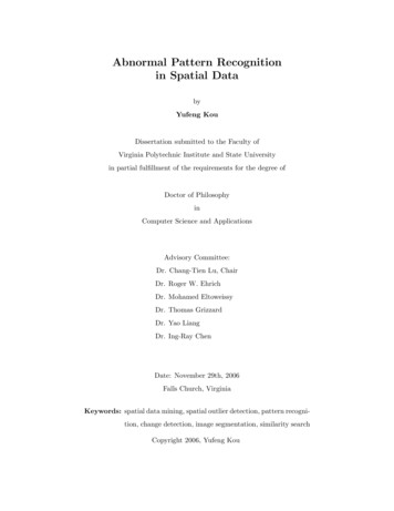
Subsequently, difficulty was encountered in properly aligning the system, and theimagery produced was of poorer quality than that seen earlier. The current systemhardware seems "fragile," as alignment procedures had be performed prior to each testprocedure, and this alignment does not maintain over night. In addition, "warm-up"periods as long as 1 hour were required prior to evaluation. Also, the left-side videoboard failed to produce imagery equal in quality to that of the right-side video boardduring testing. Therefore, the right-side video board was used to drive both sides duringthe tests reported here.Photographic measurement of spatial resolutionTo avoid the problems of temporal noise affecting measurements, we used stillphotography to capture HMD imagery using a quasi-linear charge-coupled device (CCD)camera and a computer capture card. Software allowed us to evaluate the images byconverting the unsigned gray shade values (8 bits of resolution) into whole numbers (0 to255) for numerical analysis. Image capture was aided by a device, built by USAARL,which maintained alignment of the camera lens with the HMD's exit pupil (Figure 1). Inmost cases, laser intensity was adjusted to produce photographic images where the graylevels ranged over the whole 8-bit range without saturation. It should be noted, the noisecharacteristic of our measurement system was not considered in these calculations.Removing the bitmap noise from the data would likely have a positive affect by showinghigher contrast and modulation levels than those reported here. This shortcoming isinherent in the photographic method but can be reduced by using cameras better suitedfor mensuration.Modulation transfer function (MTF)The Microvision HMD uses a display format of 1280 by 960 pixels. Using anapproximate field-of-view (FOV) of 41 degrees by 30.75 degrees, one-degree square ofvisual angle contains approximately 975 pixels (31.22 pixels per linear dimension). Thisrelates to a Nyquist frequency of 15.61 cycles/degree ((31.22 pixels per degree)/2). Inthe previous system, the horizontal MTF barely showed measurable modulation at theNyquist frequency (Figure 2). The RAH-66 Comanche specification calls for an 8percent modulation at this frequency.
Figure 1. Photographs of optical set-up showing relationship between the HMD optics and camera lens. Inthe top photograph, note the image of the exit pupil centered on an artificial 3mm iris. For all ofthe data shown in this report, a 5mm iris was used. The device holding the camera allowedviewing of any FOV position while still maintaining correct alignment.
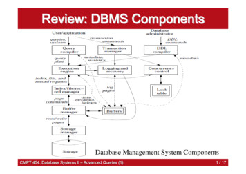
0102030405060Spatial frequency (cycles/deg)Horizontal MTFVertical MTFFigure 2. Vertical and horizontal MTFs measured previously (Harding, et al., 2001). Note the differencebetween the two curves at the Nyquist frequency (horizontal 0.05 and vertical 0.20).Central monocular area MTFTo make comparative measures and to evaluate Microvision's design progress, linespreads were measured for the horizontal and vertical orientations with the system wellcalibrated and the HMD imagery properly aligned with the camera. Figure 3 showsphotographic images of the horizontal and vertical lines captured from the left-side optic.Figure 4 shows the MTFs obtained from these photographic images. Note the increase inmodulation at the Nyquist frequency for the horizontal MTF.
Figure 3. Horizontal and vertical lines captured by a grayscale camera. These lines reflect the bestimagery we obtained from the system. o DNEiocoroZJT3O10152025303540455055Spatial frequency (c/deg)horizontal MTF (left side) -«-vertical MTF (left side)Figure 4. MTFs measured from the left side of the HMD. Like before, the vertical MTF shows about 0.20modulation at the Nyquist frequency. The horizontal MTF showed modest improvement withabout a 0.12 modulation at the Nyquist frequency.The horizontal MTF shows modest improvement in that the performance exceeded theComanche specification. These curves were taken from lines well centered in the middleof the 1280 by 960 pixel array.
Central binocular area MTFSince the HMD design is biocular with a binocular overlap, the n: sal 25 degrees fromeach side is overlapped. It is important to assess the MTF in the middle of the overallFOV. To accomplish this, we captured line profiles at 12.5 degrees from the nasal edge.Figure 5 shows MTFs calculated from the photographed line profiles from the left side.Little difference was observed between the peripheral MTFs and the central MTFs. Wehad expected modest differences based upon Microvision's reported data from the leftand right periphery, yet found no noticeable performance fall-off. This bodes well forbinocular viewing as the MTFs exceeded the Comanche specification at the Nyquistfrequency. Horizontal MTF Vertical MTFFigure 5. MTFs taken from the left side for lines centered 12.5 degrees from the nasal edge.Point spread function (PSF)Microvision had found higher modulation at the Nyquist frequency by calculating theMTF from the PSF. In a linear system, the line spread and point spread should providethe same frequency information for a single dimension. However, Microvision's laser
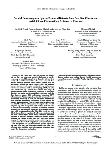
scanning technique produces spatial images that are noncontinuous, and multi-pixelpatterns cause spatial inconsistencies that weaken the system's spatial resolution. Forexample, at the Nyquist frequency, a grill pattern's fast Fourier transform (FFT) containsconsiderable noise (unwanted spatial frequency modulation) that degrades an observers'ability to identify the orientation of the grill pattern (see CTF noise below).Thus, we feel that the PSF may inflate the actual frequency response of the HMD. Asa casual aside in support of this notion, the geometry of vertical and horizontal lines isnot constant, but rather is dependent upon scaling and/or various alignment procedures.For example, often, a single line may look like a rope with a spiral geometry and, at othertimes, the spiraling is not readily observed. This geometric inconsistency would produceline spreads that are different. Thus, we feel that MTFs based upon line spreads providemore accurate data. In an attempt to duplicate Microvision's conclusions, we measuredthe MTF from a PSF. A photographic image of a single pixel in the middle of the FOV isshown in Figure 6.Figure 6. Enlarged photographic image of a single pixel located in the middle of the FOV. Thephotographic image is 64 by 64 pixels that represents a square field of about 0.3 degree ineach dimension. Note the essential ghost duplication in the mage. For our measurement of thePSF, we used an image size of 256 by 256, in order to add resolution.Figure 7 shows the spectral distribution calculated from the pixel shown in Figure 6.Calculating the modulation at the Nyquist frequency, we found a modulation depth of0.10 (horizontal MTF) and 0.24 (vertical MTF).
Figure 7. Photographically enhanced two dimensional frequency spectra of pixel image in Figure 6. Priorto the two-dimensional FFT, the dc (gray level of 12) was subtracted from the image shown inFigure 6. Note the rather symmetric frequency modulation.Contrast transfer function (CTF)CTFs were measured using different techniques in order to better characterize thespatial resolution of the system. Following vertical or horizontal alignment, photographicimages of grill patterns were collected. As a side note, HMD imagery did not produceorthogonal rows and columns. They were about 2 degrees off normal. Thus, realignmentwas necessary when measuring contrast between rows and columns. In ourmeasurements, alignment was critical because data were collapsed in one axis(dimension) to produce an average modulation in the other axis. For example, to measurethe contrast for a horizontal grill pattern, data were collapsed horizontally over a numberof data points to produce a one-dimensional curve.The first CTF measurement technique was rather straightforward. Maximum contrastwas measured by averaging the peaks and troughs in the collapsed data to determine anaverage peak and an average trough Figure 8 shows data collected from the 1-on/l-offgrill pattern. The peak was the average of the five peaks identified in the chart.Likewise, the trough measurement was the average of the six troughs. Using thistechnique, horizontal and vertical CTFs were measured for the left side (Figure 9). The0.25 contrast value measured for the vertical 1-on/l-off grill pattern represents a majorimprovement in the system. Last year (Harding et al., 2001), an average contrast ofapproximately 0.025 was measured for the vertical grill pattern.8
250ö 10050Vertical position 1 on 1 off PeaksTroughsFigure 8. Peaks and troughs used to measure the CTF contrast.0.90.8J0.72 0.6cJ0.5X*0.4 *inIS0.3Im4-ic0 0.2o0.10.1110100Spatial frequency (cycles/deg)"Vertical frequencies (horizontal grill pattern)* Horizontal frequencies (vertical grill patterns)Figure 9. Horizontal and vertical CTFs measured for grill patterns in the left side's central area. Note thesharp fall-off at the Nyquist frequency.CTF noiseWhen viewing the HMD imagery at the Nyquist limit, it is difficult to discern theorientation of the grill patterns. In fact, for the vertical grill pattern, an observer is morelikely to observe a horizontal grill than a vertical grill. This is a problem with the nature
of the pixel structure. With older CRT systems, there was never a problem in identifyingthe orientation of grills if given sufficient contrast However, the Microvision system is apixilated display much like a flat panel display. Using terminology from flat panels, thepixel geometry in the Microvision system has a fill factor of less than one, i.e., the activepixel does not occupy all of the pixel space represented by the angular subtense of pixelspacing. Thus, the two-dimensional spectra of a grill pattern has spatial frequencycontent in multiple orientations. Older CRTs had spatial frequency content in only oneorientation, per se. This multidimensional frequency content leads to mistakenrecognition of orientation. If we consider spatial frequency content that is not in theappropriate orientation as noise, then it is possible to calculate signal to noise ratios forgrill patterns.To simplify the noise calculation, we used a shortcut of collapsing data orthogonal tothe orientation of the grill pattern. Figure 10 depicts this method of measuring signal andnoise. In Figure 10A, the noise would be the profile at the bottom and the signal wouldbe to the right. The opposite case would be used for the grill pattern shown in Figure10B.m,,-M MMMW»-« ,.j, gjg iTF. Ji -JF JT P*.Bitt:tt:MB;[(a ?#flH 4' BI m'a- - FjF.jF.jirI mM-., ,1,f* i' aiunrf * * * » 133 Tmr r Ss r TEfTT»T!Figure 10. Photographically enhanced images of 1-off/l-on grill patterns in the horizontal (A) and vertical(B) orientations. Of note is the pixel structure observed in B. Here a strong horizontal elementis noticed. This element makes recognition of orientation difficult. Profile amplitudes are notnecessarily to scale.In this analysis, a more robust method of measuring contrast was used, which takesinto account the variability of the waveform. Standard deviations were calculated for thesignal and noise curves. To normalize the data, the standard deviations were divided bythe means. Figure 11 shows CTFs measured using this technique. Of particular note, atthe Nyquist frequency, the noise contrast for the vertical grill pattern was higher than thesignal contrast. This would explain the difficulty in correctly identifying the orientationof the vertical grill pattern. In Figure 12, we plotted the signal to noise ratios for the sixspatial frequencies and two orientations. Also plotted in this figure are calculations taken10
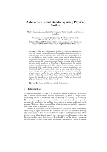
from images provided by Microvision. With the exception of the one wayward point, thedata were nearly identical. This provides additional support for the robustness of themethod.0.1110100Spatial frequency (cycles/deg) Horizontal Grating Signal Noise 0 "Vertical Grating Signal Noise Horizontal Grating Noise- O - Vertical Grating NoiseFigure 11. CTFs measured using the standard deviation technique for grill patterns presented to the leftside. Here the noise estimates are plotted as a function of grill spatial frequency. As a sidenote, the noise frequency spectra is highly correlated with the pixel spacing and is thuscomposed of higher spatial frequencies (near the Nyquist frequency). Since the Nyquistfrequency is well within human spatial frequency bandwidth, we feel justified in using ournoise estimates in this fashion.11
100.0COocHc10.0OJ10ora10.110100Spatial frequency (cycles/deg)-o-- Horizontal GratingsMicrovision Vertical' Vertical Gratingsi - - Microvision HorizontalFigure 12. CTF signal-to-noise ratios based upon the data shown in Figure 11. Microvision engineersprovided us photographic images of grill patterns used in their data analysis. Using theirimages, we calculated the signal-to-noise ratios for the highest two spatial frequencies. Withthe exception of the aberrant point, their data fell on top of our data points.Character resolution at the spatial limitTo evaluate the system's ability to produce imagery at the spatial limit of resolution, atarget consisting of 5 by 5 characters was constructed and presented normally and at 90degrees rotation. The smallest gap in these characters was one pixel - the spatial limit.Figure 13 shows photographs of this imagery. Although, the system may not have beenin perfect alignment, the "waviness" of the characters and loss of pixel definition furthersuggest the lack of system geometric precision.12
Figure 13. Photographic images of 5 by 5 character sets presented normally (bottom) and 90 degreesrotated (top). Note the slight misalignment of character elements.SummaryThe data reported here show an improvement in the MTF, which meets the Comanchecontrast requirement at the Nyquist frequency. Microvision's new electronics madepossible this increase in modulation at the higher spatial frequencies (observed in theMTF and traditional CTF) when considering only those single orientation spatial13
frequencies. However, when a noise analysis is used, we saw that the horizontal MTF'smodulation at the Nyquist limit was handicapped by the noise modulation. Theperceptual relevance of this noise pattern is revealed in the inability to identify theorientation of the vertical grill pattern at this frequency.Explaining some of the differences observed between Microvision's measurements andour own is more difficult. Certainly the noise level of our camera may play a role.Additionally, we noted in Microvision's captured images that gray level representation ofluminance was limited to about six bits (gray levels of 0 to 63) even though they reportedusing a 12-bit camera. In our measurements, we made it a point to drive the system ashard as we could without saturating our camera.The HMD's inability to hold calibration/alignment is a major concern. A contributingfactor is the system's complexity; there are a large number of subsystems that mustperform optimally in order to produce quality imagery.14
ReferencesRash, C.E., Harding, T.H., Martin, J.S., and Beasley, H.H., 1999. Concept phaseevaluation of the Microvision, Inc. Aircrew Integrated Helmet System HGU-56Pvirtual retinal display. Fort Rucker, AL: U.S. Army Aeromedical ResearchLaboratory. USAARL Report No. 99-18.Harding, T.H., Martin, J.S., Beasley, H.H., and Rash, C. E. 2001. Final phase Ievaluation of the Microvision, Inc. Aircrew Integrated Helmet System HGU-56Pscanning laser display. Fort Rucker, AL: U.S. Army Aeromedical ResearchLaboratory. USAARL Report No. 2001-06.15
Appendix.List of manufacturers.Micro vision, Inc.19910 North Creek ParkwayP.O. Box 3008Bothell, WA 9801116
8SI8iÜI: lllfliiDEPARTMENT OF THE ARMYU.S. Army AeromedicalFort Rucker, Alabama 36362-0577
The final Phase II version of the Microvision, Inc., Aircrew Integrated Helmet System (AIHS) HGU-56/P scanning laser display was evaluated for spatial resolution performance. The data reported herein show an improvement in the modulation transfer function (MTF) over the Phase I system. The following modulation values, which meet the RAH-66 Comanche