Transcription
The Effect of Ventilation and Hand Holeson Loss of Compression Strength inCorrugated BoxesJ. SINGH 1,*, E. OLSEN3, S. P. SINGH4, J. MANLEy2 and F. WALLACE2lAssociate Professor, Industrial Technology, Cal Poly State University,San Luis Obispo, CA2Research Assistant, Industrial Technology, Cal Poly State University,San Luis Obispo, CA.1Assistant Professor, Industrial Technology, Cal Poly State University,San Luis Obispo, CA.4Professor, School of Packaging, Michigan State University, East Lansing, MIABSTRACT: Corrugated packaging is used to package approxi mately 90% of all products that reach retail store shelves and aisles inthe United States. A large number of these corrugated shippers areused to ship fresh produce and perishables through the cold-chainenvironment that requires these boxes to have venting to permit air cir culation. In addition, corrugated boxes for that are large in size andcontain heavier products, may have hand holes to facilitate manualhandling. The presence of ventilation and hand holes both cause aloss of material in two or more faces of the box. As a result the com pression strength required for shipping and stacking is compromisedand can result in damage to contents. Hand holes that do not meettheappropriate strength requirements can be a safety issue in manualhandling if the contents are released when handling. This study wasinitiated to understand the loss of compression strength in corrugatedcontainers as a function of size, shape and location of ventilation andhand holes used for handling ergonomics and extending shelf life forperishables with good air flow. Based on experimental data, resultsshow that the loss in strength can range between 10 to 40% and is sig nificantly larger than previously reported.1.0 INTRODUCTIONDUE to its high strength to low weight ratio corrugated packaging ispoised as the leading choice for transport packaging in the UnitedStates. By some estimates corrugated packaging is used to package ap proximately 90% of all products for retail distribution in the United*Author to whom correspondence shonld be addressed. Email:jasingh@calpoly.eduJournal of Applied Packaging Research, Vol. 2, No. 4-June 20081557-7244/07/04 227-12 2008 DEStech Publications, Inc.227
228J. SINGH, E. OLSEN. S. SINGH, J. MANLEY and F. WALLACEStates [I]. The popularity of corrugated packaging also stems from thefact that it is practical, useful, economical, renewable and recyclable [I].It is also a substrate that can be custom designed and provides excellentmerchandising appeal through printing on box panels. Twede [2] ac counted that 80% ofthe 46 billion worth ofpaper based packaging usedis corrugated fiberboard shipping containers.Corrugated shippers are designed to overcome the distribution envi ronment hazards so that the products they carry reach the consumers, in tact and ready for use. The transportation and warehousing hazardsfaced commonly by corrugated shippers include compression, shock,vibration, temperature, creep and humidity among others. Corrugatedshippers often have holes to allow for ventilation to perishables and per mit air circulation in the cold chain shipping and storage environments.In addition packaging designers may offer hand holes to permit manualhandling of boxes that are either large in size or carry heavy products.The hand holes often improve ergonomics and assist in handling associ ated with large or awkwardly designed containers. It is important thatthe strength of the hand hole be sufficient so that the contents are not re leased during exposure to normal stresses that are likely to occur duringmanual handling. Failure of a hand hole structure on a corrugated boxcan release the contents causing damage or injury.Some guidelines for designing hand holes for corrugated boxes areprovided by ASTM D 6804, which is a standard guide for "Hand HoleDesign in Corrugated Boxes" and is intended to test the performance ofhand hole strength [3]. It provides guidelines for designing pre-cut aper tures intended for use as hand holes in corrugated boxes during manualhandling of boxed cargo. Although this standard offers guidance forpackage development and for subsequent testing of boxes to measureperformance, it is not intended to provide specific information on the de sign of hand holes [3]. The standard recommends that the designers fol low best practices when designing hand holes for corrugated shippersbut also take into consideration the product and package weight whendeciding on the proper use of a hand hole.It is obvious that removing any material from the load bearing verticalfaces of a container would lead to a decrease in its overall compressionstrength. This paper concentrates on evaluating the effect of eliminatingcontrolled amounts of corrugated material, in the forms of ventilationand hand holes, from RSC style boxes on the overall compressionstrength of the container. The purpose of this study was to establish a re
The Effect of Ventilation and Hand Holes229lationship that can be used to correlate the percentage of corrugated ma terial removed from the sidewalls of containers to the loss of compres sion strength of the container. While it has been obvious and known thatboth ventilation and hand holes produce a loss of box strength, there hasbeen very little published information quantifying this loss.In a recent study by Han and Park [4], finite element analysis (PEA)was used to predict the loss ofcompression strength due to vent and handholes. The authors also used actual testing on fifteen different styles ofboxes and hole patterns. The study used double-walled corrugated boxeswith dimensions of 41 x 30 x 25 cm and the surface area occupied by theholes was approximately 2% of the total surface area of the vertical facesof the boxes. The study reported a compression strength loss of less than10% based on FEA and experimental data. However, there are a few lim itations of this study. It has been the experience of the authors ofthe pres ent research that compression strength losses for single-walled corru gated boxes exceed 10% due to the presence of any type of ventilation orhand holes. The difference between the results reported between the pastpublication [4] and the present study is very likely due to the structuraldifferences such as the number of walls and the dimensions of the boxestested as well as the surface area covered by the holes on the verticalwalls. The present study focuses on single-walled corrugated containersthat are used in more than 90% of all applications in the US. [1]This study evaluated the following two objectives:1. Effect of location of ventilation or hand holes in corrugated shipperson loss of compression strength2. Effect of shape and size of ventilation or hand holes in corrugatedshippers on their loss of compression strength2.0 MATERIALS AND METHOD2.1 Corrugated BoxesAll corrugated box samples used for this study were created usingArtiosCAD software and the Premium Line 1930 model of theKongsberg table (Esko Graphics, Ludlow, Massachusetts, USA). Sin gle-walled Regular Slotted Container style (FEFCO 0201) boxes mea suring 50.8 cm x 40.64 cm x 25.4 cm were used for this study. The corru gated fiberboard used was C-flute with basis weight of 215/162/215
230J. SINGH, E. OLSEN, S. SINGH, J. MANLEY and F. WALLACEg/m2, bursting strength of 12.70 kgf/cm2, and edge crush test (ECT)value of 8.09 kgf/cm. All boxes had the flutes running in the top to bot tom direction in the assembled stage. All samples were conditioned at 23 I C and 50% relative humidity for 48 hours prior to testing in accor dance with ASTM D4332 [5]. Five replicates for all variations of handholes and vent holes were tested for compression strength.All compression tests were conducted using a Lansmont Model152-30 compression test system (Lansmont Corporation, Monterey,CA, USA) and in accordance with ASTM D642 [6]. A preload of 22.68kgf was applied to all specimens prior to observing the compressionstrength values. The fixed-platen mode of the compression tester wasused to conduct all testing at a speed of 12.7 2.5 mm/min until failurewas observed.2.2 Hand HolesFor this phase of testing, a standard sized (8.89 em x 2.54 em) handhole was cut out on the smaller opposite vertical faces of the RSC con tainers. The goal of this phase was to attempt to identify any relationshipbetween the location of the hand hole and the overall compressionstrength of the container. The locations of the hand holes are shown inFigure 1. Hand Hole Locations.
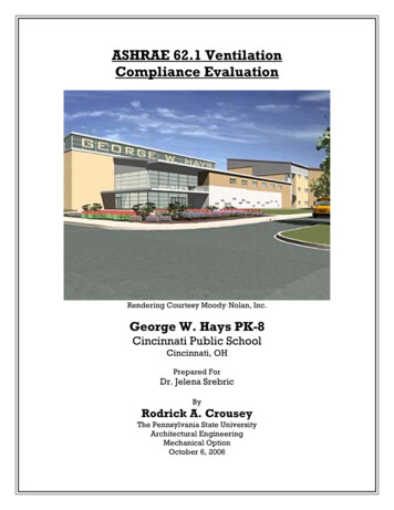
231The Effect of Ventilation and Hand Holes,,,". . M -- .- . . . . . .- .- . emSO.8C1l1Design 1.--. . - . - . - - -. . . .- 4/ "Design 2. .T 3.5em2.5 ani---i -;::::t- I::.:: '"T'"I!SO.lcmDesign 3De.'Oign 4Lr-.-.-."--f:y f.L. - - -L.- - cm-L.-. --'--.- . -. - .DesignSFigure 2. Vent Hole Design Specifications.Figure 1. For the vertical locations, the lowest position started at 8.47 emfrom the center of the bottom (one third of the height of the containerfrom the bottom). The remaining hand holes were cut out at a distance of2.54 em from this starting position. For the diagonal locations, the start ing (bottom) location was the same as that for the vertical hand holes.The remaining five locations were placed along the diagonal line thatwent through an upper comer of the face through the center of the bot tom-most hand hole, at a vertical distance of2.54 em between every sub sequent location.
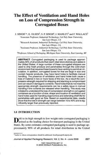
232J. SINGH, E. OLSEN, S. SINGH, J. MANLEY and F. WALLACEAll locations of the hand holes were symmetric for both short faces onwhich they were cut out. Compression tests were conducted for five rep licates of each configuration of the hand holes. A total of twelve designswere tested.2.3 Vent HolesThis part of the study examined the relationship between the increas ing vent hole sizes placed on the largest vertical faces of the corrugatedcontainers to the decreasing compression strength of the container. Toachieve this, five vent designs were created and each design had fivevariations, which removed 10%,20%, 30%, 40% and 50% of the corru gated material from the side panels. Figures 2 and 3 show the details ofthe size and shape of vent holes tested.Table I shows the dimensions for all vent hole designs as related to thepercentage of material removed from that face. The compression testswere conducted for five replicates of each configuration of the handholes.Figure 3. Vent Hole Test Samples.
:;:!CD .ooCi3'Table 1. Vent Hole Dimensions.Area Removed*-.Vent Hole Dimensions - em and (Quantity per Side)%em 2Design 20.312.7*20.315.9*20.3Design 2(3x)R R R R R 3.705.236.417.408.27Design 3(2x)Design 4(4x)Design *20.33.2*20.34.8*20.36.4*20.37.9*20.3R 3.2R 4.5R 5.6R 6.4R 7.2a;:;:) IIIa:;:)§Q. ;:)*Area removed reflects the total surface area cut out of the vertical faces for the vent holes.Q.a J\)(,,)(,,)
J. SINGH, E. OLSEN, S. SINGH, J. MANLEY and F. WALLACE2343.0 RESULTS & DISCUSSION3.1 Hand HolesTable 2 shows the means and standard deviations for the compressiontesting results for the twelve different hand hole locations as comparedto the relative values for control samples. The mean and standard devia tions for controls (no material removed from vertical faces) were: peakcompression force of 2587 and 60 N and peak deflection of 0.49 and0.02 cm respectively. Five samples were tested for each variable stud ied.Regression analyses of the vertical and diagonal distance data andtheir interaction did not indicate a significant relationship between handhole location and compressive force or deflection. Table 2 shows theTable 2. Compression Test Results for Vent Holes.Force.(N)meanstd dev99170nDiaaonal Distance (em)3. 2. IDeflect(em)I 1155. 7.8.8Force and Deflection % Control ValuesForce I )(N)ForceI Deflect(em)(N)Force11.7IDeflect(em)(N)ForceI Deflect(em)(N)2574981831.6I98101591i62.5I 02129 .810.291:812.791;5I4All100151::7I es: (1) Outliers removedfrom table(2) Mean and standard deviation/or controls (zero material removed): Compression 2587, 60 NDeflection 0 .49, 0 .02 cm
235The Effect of Ventilation and Hand Holes. weak relationship between the compressive force and each vertical anddiagonal location.3.2 Ventilation HolesTable 3 shows the means and standard deviations for the compressiontesting results for the five designs for vent holes tested as compared tothe relative values for control samples. Each design had five differentpercentages of material removed and five samples were tested for eachconfiguration.The data were analyzed first using a 2-way analysis of variance. As ex pected, the designs, percent material removed, and their interaction weresignificant (p 0.000). The strength of each design reduced in a linearfashion in correlation with the percent of material removed. Individualregression analyses for each design were significant (p 0.000) and hadTable 3. Compression Test Results for Vent Holes.Design12345AllCompression Strength % Control Value (N)meanstd 627812010n "0Q) 0EQ)a:""iii. 1ii:2AllNotes:(1) Outliers removed from table(2) Mean and standard deviation for controls (zero material removed) 4177, 141N.
236J. SINGH, E. OLSEN, S. SINGH, J. MANLEY and F. WALLACEadjusted r-squared values ranging from 78.4% to 97.3% indicating agood fit to a linear model (Table 4).One way to compare the compression strength performance ofthe var ious designs is to examine the regression coefficients for the percent ma terial removed versus the parentage reduction in compression strengthfrom the control units. The control units had no venting. The five controlunits had an average strength of 4177 N. Table 4 shows coefficients forthe intercept and the percent material removed variable. A significantpositive intercept value can be interpreted as a "zero percent removed"design penalty. For example, Design I predicts a 12% reduction instrength even if the percent of material removed is zero. It should bepointed out that predicted strength values based on the coefficients inTable 4 are only applicable within the material removal range tested(10-50%). Design 4 became unstable at the 50% level. These five datapoints, showing approximately an 80% strength reduction as shown inFigure 4, were removed to calculate the values in Table 4.A reasonable expected value for the percent material removed coeffi cient would be 1.0. This means that predicted compression strength re duced the same percentage as the material removed. A coefficient higherthan 1.0 means that strength is being reduced faster than material is be ing reduced. A coefficient less than 1.0 means that strength is being re duced proportionally less. For example in Design 1, strength is reducedby 0.56% for every 1.0% of material removed on average. Alternatively,both circular designs reduce in strength by 1.08% for every 1% of mate rial removed.All of the mean strength reduction values shown in Table 4 are signifiTable 4. Regression Results for Vent Holes Sorted byMean Strength Reduction.Coefficients% MaterialDesign 1Design 4 (2)Design 3Design 5Design 2InterceptRemovedAdjustedR-SqMean StrengthReduction % 5%97%96%30.1 %32.3%33.2%45.5%45.5%NDtes:(1) Expected value fDr strngth reductlDn equal tD materil reductiDn is 30%.(2) Desikgn nDt linear abDve 40% material remDval.
237The Effect of Ventilation and Hand HolesScatterplot of Strength Reduction% vs Removed%Design170%-II-60% S-6'".i.IX 2. - .3.4-A-50%40%30%20% 10% '--.---,----,,30%10%-,40%--,---'50%ReJmved%Figure 4. Regression Plots for Vent Hole Tests.cantly different, except for the two circular shapes: Designs 2 and 5. Theorder of the designs in Table 4 has interesting implications for vent holedesign. Rectangular holes seem to offer significant strength advantagesover circular holes. Even the parallelogram Design 3 is significantlybetter than the circular designs. This is interesting in that one might ex pect that designs with comers would be at a disadvantage because of cor ner tendency to add to stress concentrations. This is a possible explana tion why Design 4 with 4 rectangular cutouts per side performed morepoorly that Design 2 with only 2 cutouts.4.0 CONCLUSIONS1. The presence of ventilation and hand holes can cause strength reduc tion between 20 to 50% in single wall corrugated shipping containers.2. The shape of the hole is critical in loss of strength. Vertical holes thatare rectangular or parallelogram in shape are better in retaining corru gated box strength as compare to circular holes.3. A linear relationship exists between the loss of strength and the to tal area of the holes made for venting or handling. This relation ship does not stay linear when over 40% of the face material is re moved.
238J. SINGH, E. OLSEN, S. SINGH, J. MANLEY and F. WALLACE5.0 REFERENCES1. International Corrugated Packaging Foundation, Corrugated Curricula-Course Materials onCorrugated Packaging, http://www.icpfbox.orgl, accessed February 4,2008.2. Twede, D. and S. Selke, Cartons, Crates and Corrugated Board: Handbook of Paper andWood Packaging Technology, ISBN No: 1-932078-42-8, DEStech Publications Inc., Lancas ter, PA USA, 2005.3. ASTM D6804, Standard Guide for Hand Hole Design in Corrugated Boxes, Vol. 15.10,American Society of Testing and Materials, West Conshohocken, PA, USA, 2007.4. Han, J. and J. M. Park, Finite Element Analysis of VentlHand Hole Designs for Corrugated Fi berboard Boxes, Packaging Technology and Science, 2007, Volume 20, Issue 1: 39-47.5. ASTM D4332, Standard Practice for Conditioning Containers, Packages, or Packaging Com ponents for Testing, Vol. 15.10, American Society of Testing and Materials, WestConshohocken, PA, USA, 2007.6. ASTM D642, Standard Test Method for Determining Compressive Resistance of ShippingContainers, Components, and Unit Loads, Vol. 15.10, American Society ofTesting and Mate rials, West Conshohocken, PA, USA, 2007.
manual handling. Failure of a hand hole structure on a corrugated box can release the contents causing damage or injury. Some guidelines for designing hand holes for corrugated boxes are provided by ASTM D 6804, which is a standard guide for "Hand Hole Design in Corrugated Boxes" and is intended to test the performance of hand hole strength [3]. It