Transcription
RECOVERING THE RIFE MICROSCOPE: A HOLOGRAPHIC DEVICEDEVELOPED 50 YEARS “AHEAD OF TIME”.Introduction:During the 1930’s there was a gentleman named “Royal Rife” who claimed to havean optical microscope which was capable of 10,000 X’s magnification.To find out details on Dr. Rife’s work (the Doctor is an Honorary title, howeverafter making the discoveries I have made I will GLADY give Dr. Rife this title, hedeserves it!) please visit these p://www.rifeenergymedicine.com/AppAH.htmlThe problem with Dr. Rife’s claims, as can readily be seen from examining thesewebsites is that there is a well known phenomenon in optics called the “Abbe Limit”Or the FRAUNHOFER DIFFRACTION limit.What this limit does for optical microscopy is to state that due to problems with thediffraction of light around bodies of the size of the wavelength of visible light (550 to200 nanometers), the maximum optical magnification (useful) is limited to about2000 X’s.Yet Dr. Rife, (as can be seen from the websites) clearly claimed to be obtainingmagnifications of the order of 10,000 to 40,000 X’s.Based on Dr. Rife’s observations of “live, real time” observations of bacteria andviral action(s), Dr. Rife developed the “Rife Ray Device”.For more detail on the “Rife Ray Device”, I would recommend that one go to thefollowing website:http://www.rt66.com/ rifetech/There one will find an excellent an very complete discussion of the Rife Ray device.Although Dr. Bare’s work is very complete and technical, it does take some time towork through reading the material. Thus I will attempt to write a paragraph
description of the “Rife Ray Device” and give a tentative, (although not definitive)explanation of how it works.The “Rife Ray Device” is essentially a “low grade” inert gas MASER (microwaveamplification by stimulated emission of radiation).The “stimulation” is by an RF (Radio Frequency) signal applied to a He/Ne orHe/Ar tube. Typically in the 20-30 MHz range.This RF signal is also AMPLITUDE MODULATED by some sort of audiofrequency.What Dr. Rife discovered was that using his microscope he could observe that asvarious audio frequencies were applied to the “Ray Device”, he could find aparticular frequency for a particular organism which would cause the organism tobreak apart.Dr. Bare has built, patented (a variation) and markets the INFORMATION toduplicate the Rife Ray devices.Because of the TREMENDOUS power of the “medical establishment”, Dr. Baredoes not market these devices for “therapeutic” purposes.If one builds/acquires a “Rife/Bare” device, one does it for one’s own personal“research” and with no claims implied or expressed with regard it’s ability toselectively “lyse” or destroy various micro-organisms “in vitro”. (Or in the humanbody.)This bring us again, “full circle” to the “Rife Microscope”, as it is the BASIS forRife’s various claims with regard observations he made in the 1930’s as to theactions of bacteria and viruses which to this day remain “advanced” and not fully“recovered” at this time.The problem with the Rife Microscope, is that of the 5 or 6 versions that Rifeproduced, there exist 3 of them in various private party ownership.Over the years attempts have been made to “recover” the microscopes. It is known,for instance, that Rife filled the barrels of his microscopes with Glycerin. Somevarious versions of his microscope have been filled with Glycerin and attempts toobserve organism made.From one of the above websites I will excerpt the following:
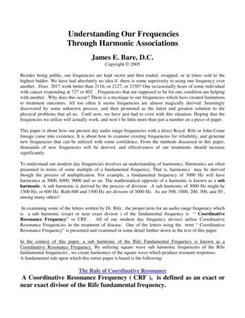
Rife No 5 was tested in 1978 while it was at the Wellcome Museum, by aProfessor of Physics from Imperial College in London. Practically the wholeinstrument was dismantled. There seemed nothing particularly remarkableabout it except that it had been constructed in such a way as to make thework of microscopy tedious and cumbersome, particularly in respect offocusing the instrument. Using all the original optics it was quite impossibleto obtain an image, but using alight-source, eyepiece and objective from aReichart microscope, a very imperfect image of leukemia blood cells wasfinally obtained. The image was about 30% larger than would have beenexpected with the use of a x6 objective and a x40 eyepiece, and this was nodoubt due to the prismatic arrangement in the barrel of the microscope. Theresolution, However, was extremely poor. It was concluded that it would havebeen impossible to produce the known photomicrographs with thisinstrument and it became clear that this explained the late Dr Gonin'scomplaint that he could obtain no results. One of the original photographslabeled "virus of cancer" was identified as a well-known artifact of opticalsystems known as "coma". It is merely a photographic rendering of ananomaly produced by defects in the optical system.This sounds pretty disparaging and almost a total indictment of the claims (bymany) that the Rife Microscope is a fraud.However, it is CLEAR from reading this that the person trying to replicate theoriginal Rife work DID NOT READ ANY OF THE EXISTING WRITINGS BYRIFE or have a background which would lead them ANYWHERE NEAR theresolution of the method of operation of the scope.When one reads the writings of Rife, one finds out several things which Rife makesclear, quite plainly.First of all, Rife refers to his Microscope as “An Interference Microscope”.To continue this discussion and demonstrate the technical reality of the RifeMicroscope, I will borrow an illustration from Gary Wade’s fine website:
The problem with the schematic above is that it obscures a very important pointwith regard the Rife microscope.Mr. Wade’s work is influenced by the erroneous concept that is “about” that Rife’smicroscope had some peculiar effectiveness due to the “Numerical Aperture” andthe length of the optical path.That is why the “optical path” is traced out with lines and arrows in Wade’sschematic. Aside from the fact that this “optical path” does not make sense i.e. itessentially shows the prism surfaces acting as mirror surfaces, it has nothing to dowith the function of the Rife Microscope.I would enjoin the reader to look at this version of Mr. Wade’s drawing:Please note my having drawn in (alas, not clearly but I believe one can still make outthe point) the outlines of the 8 prisms which have been noted to have existed inRife’s scope.Prisms P5 and P6, and P7 and P8 are “back to back” and, I believe, opticallyconnected. I also believe that prisms P2 and P3, despite being shown above as “backto back” are NOT optically connected.
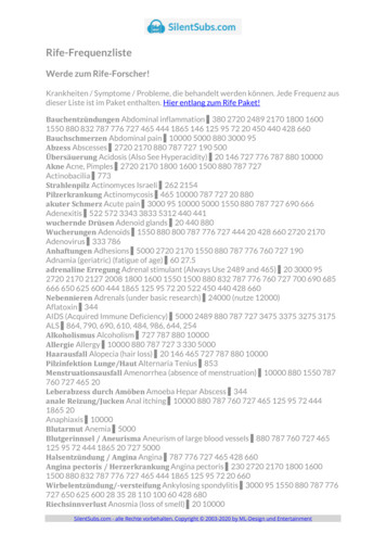
The reason I believe this to be the case will become clear upon the followingdiscussion of the work of Courjon and Boulabois (Journal of Optics, Paris, 1979,copy attached.)As the result of 2 months of searching on the Internet, I have located two pivotalpapers on Holographic Microscopes. They are attached to this document, but theircitations are:“Real Time Holographic Microscopy Using a PeculiarHolographic Illuminating System and a Rotary ShearingInterferometer”,By D. Courjon and J. Bulabois,Journal of Optics, Paris, 1979, Volt 10, No. 3And:“High Depth of Field Microscopic ImagingUsing an Interferometric Camera”P. Potuluri, M. R. Fetterman and D. J. BradyBeckman Institute, University of Illinois at Urbana-Champaign,Urbana, IL 61801 dbrady@duke.eduThis is from 21 May 2001 / Vol. 8, No. 11 / OPTICS EXPRESS 630Received March 27, 2001; Revised May 18, 2001The first paper describes in “theory” a holographic microscope. Part of the actual“practice” is accomplished. It is not clear exactly how much of the followingdiagram is “accomplished” to obtain the images shown in the paper.However, the implication is that the concept is complete. Here is the primarySchematic from the paper:
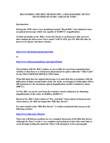
P3P4This is Figure 3. from the Courjon-Bulabois paper. This schematic cannot beanalysed in detail without another figure from the paper, figure 2. shown below:
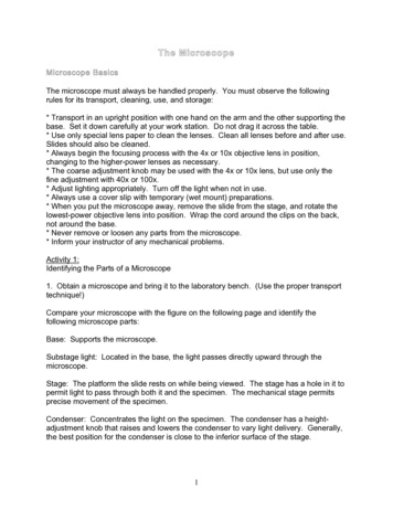
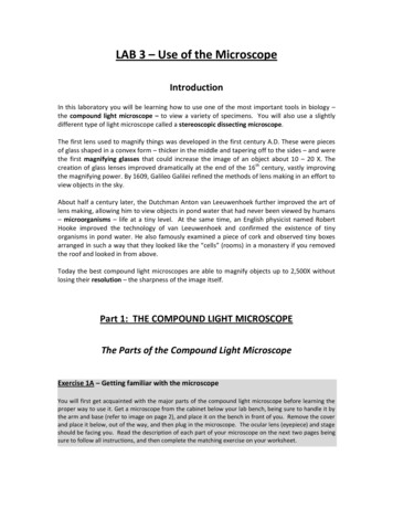
Figure 2. is a detail of the area labeled “Tr and Input Plane” in Figure 3.What Figure 2 illustrates is that the object being “examined” (or optically“enlarged”) with the holographic microscope needs to be exposed to the illuminatingcoherent/monochromatic light and an interference pattern (holograph,fundamentally) formed with a reference beam which is split through a pinhole.We shall start with this part of the device and parallel the “Rife Microscope” fromthis point forward:10.ObjectiveLens9. ObjectUnderExamIn the above 7. is a “circular diaphragm” and 8. is an convex lens.What we see happening in the above section of the Rife scope is the following:1. Between 1 to 6, the creation of a strong collimated beam.2. At step 6 the selection of a precise section of the spectrum of the light comingfrom the “mercury arc lamp”.There are several points here which should be made:First, the light coming from the source by the time it strikes the “microbe” underexamination is very much a “laser light”. I.e., mono-chromatic and coherent.Secondly, Rife makes it very clear in his writings that his goal was to find aparticular light spectrum which would cause the “microbe” to self-fluoresce.Our contention is that upon the self-fluorescence of the organism, the combinedlight “signal” going into the objective lens set at point 10 in the above is the
equivalent of the combined object and pinhole reference light of the D. Courjon andJ. Bulabois paper.Thus the optical “signal” at L1 in the C&B paper is identical to the signal that Rifewould have had at his objective lens.From this point on we come to another three key contentions:1. The prism sets in the Rife scope, being P1-P8 perform the same “inverseFourier transform(s)” that the prisms P1-P4 accomplish in the C&B paper.2. The Glycerin in the Rife microscope serves the same function as Df in theC&B paper. (This is the “rotating shearing” device, which supplies opticaldecoherence to the interference signal.)3. The Glycerin would not in and of itself supply that optical decoherenceexcept that it is “spiked” with a slight organic dye doping. Probably a methylRed or the like.It is believed that the parallels between Rife’s microscope and his method ofoperation supply us with a complete picture of the “how and why” of thefunctionality of the device when examined in light of the Holographic microscope.In the C&B Paper, the ability of the Holographic microscope to magnify an imagebeyond the normal “Abbe Limit” is explained mathematically thus:
The above equations express the Fourier transform of the image by the opticalprocessing. In the above expressions a small “g” is used in the text area, and itreflects the “intensity distribution” without phase information, where thein the integral represents a more correct vector quantity with the phaseinformation in it.The C&B Paper goes on to analyze the output intensity distribution thus:
C&B Continue to derive:Thus on a theoretical basis they believe that the image magnification is “unlimited”.They do, however, supply the following limitation on the “resolution” of the image:“The main limitation is connected with the requirement of using a reference pinhole, the dimension ofwhich must be smaller than the size of the smallest details of the object, for example 50 pm for theprevious grating. Moreover, the finite size of the average graininess of the diffuser introduces anotherlimitation of resolution. In other words such a system allows large magnifications but with a limitedbandwidth.” (Page 127 of C&B’s paper.)Two more key contentions about the Rife device thus need to be elucidated:1. The “pinhole” size in the Rife Microscope is the SIZE OF THE ORGANISMUNDER EXAMINATION.2. The “graininess” of the diffuser (or optical de-coherence device) is on themolecular level. It is related to the interaction of the light “signal” with theorganic dye in the Glycerin.Although the author of this work has known of the Rife Microscope for about 5years, only in the last three months has the author undertaken a serious study of thedevice.The first two months involved study of many optics references, including but notlimited to:1. “Optics” by Eugene Hecht, Second Edition, Addison-Wesley, 1987.2. “Engineering Optics”, by Keigo Iizuka, Second Edition, Springer-Verlag,1983.I’m particularly indebted to Dr. Iizuka for an incredibly fine text, with numerousreferences and tremendous examples, which was very important in helping melocate the work by the French researchers.During the time period of December 31st, 2003 to January 6th, 2004 I was on travelvisiting my Mother in Peoria AZ. Although there were a variety of “domestic tasks”involved with this trip, I did have enough time to continue work on the Rifemicroscope and it was during this time that I was able to locate the papers by
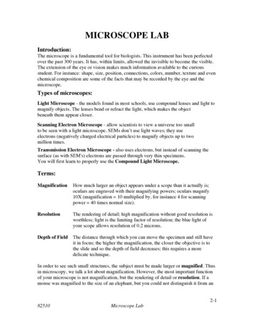
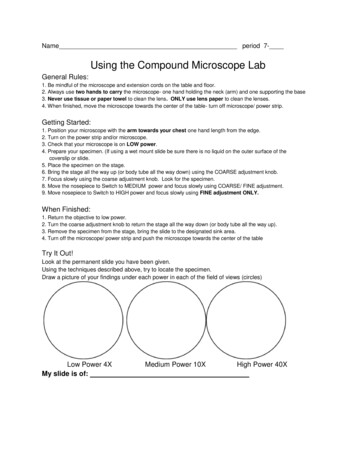
D. Courjon and J. Bulabois, and the paper by P. Potuluri, M. R. Fetterman and D.J. Brady.The work by Potuluri, Fetterman, and Brady, although not discussed in detail here,gave me further evidence of the reality of Courjon and Bulabois theoretical claims,as the PFB paper details actual construction and application of a“Rotating/Shearing Interferometric Holographic Microscope”.Now we come to the section of this work that perhaps should be titled:REDUCTION TO PRACTICE OF THE RIFEMICROSCOPETo begin with, let us show the following picture:LaserLightSourceMicroscopeSlideL2L1 Optical De-coherenceDye Doped GlycerinInverseFourierTransPorroPrismSet
A series of experiments were preformed with this test set up over the time of Saturday, the10th of January 2004 and into Sunday, the 11th of January 2004.The experiments allowed the author to determine that there was good evidence of thefunctionality of the “dye-doped” glycerin to accomplish the needed “optical de-coherence” toobtain the complete inverse transform of the “microscopic holograph”, which would be a keyelement in proving the functionality of the Rife Microscope.
RECOVERING THE RIFE MICROSCOPE: A HOLOGRAPHIC DEVICE DEVELOPED 50 YEARS "AHEAD OF TIME". Introduction: During the 1930's there was a gentleman named "Royal Rife" who claimed to have an optical microscope which was capable of 10,000 X's magnification. To find out details on Dr. Rife's work (the Doctor is an Honorary title, however