Transcription
Alarming Experience withUngrounded Tertiary BusGround DetectionGary L. Kobet, P.E.Tennessee Valley AuthorityPresented to 75th Annual Conference for Protective Relay Engineers at Texas A&M UniversityMarch 27-31, 20221
Outline Review – Ungrounded systems Ungrounded tertiary bus groundfault detection TVA experience with tertiary busground detection Industry standard/guide review Discussion of settings and action oftertiary bus ground detection Pickup Time delay Alarm or trip?2
Ungrounded Systems No intentional ground Grounded only by naturalcapacitance of system Generally not recommended(but frequently used) PRO: Very low fault current Minimize equipment damage Not necessarily required todisconnect/isolate faulted area (Ignoring the first ground fault may leadto a second, resulting in potentiallydamaging multiphase fault) Industrial use for high continuity ofservice CON: Subject to high/ destructivetransient overvoltage Personnel hazard Possible equipment damage3
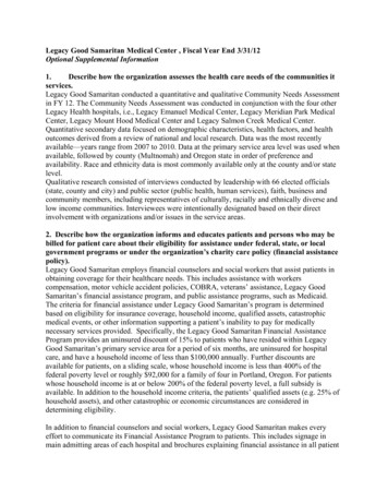
Ungrounded systemVaVcSourceDistributed naturalcapacitances between phasesaVbDistributed naturalcapacitances to groundbcaGroundfaultbcIcIbIaVan Vagn gVag 0Ground (g)Ground (g)Van -VngVcgVcn VcgVbn VbgBalanced system:Van Vag, Vbn Vbg, Vcn VcgnVbgVcnVbnNOTE: The neutral shift is thezero-sequence voltage Vng V04
Ground Detection for Ungrounded Systems Critical to detect, locate & clearground faults Easy to ignore & continueoperating Danger: Other two phases at nearly 1.732times normal line-ground voltage If insulation deterioration caused firstfault, higher voltage on other phasesmay accelerate their failure as well Result: Currents very low & don’t changewith fault location, so voltage isbest indicator As soon as ground detector isapplied, system is no longerungrounded Becomes grounded through thedetection device itself Resistance of relay & ballast resistorlimit transient overvoltages Double-phase-to-ground or threephase fault High fault current, loss of production5
Ground Detection using Three VTsNAABBCCNPrimaryVTs3.2 , 54kW74GBHGAPrimaryVTs3.2 , 54kWAuxiliaryVTsElectromechanical relay, measures 3Vo Va Vb VcMicroprocessor relay, calculates 3Vo Va Vb Vc6
Ground Detection using Three VTsNormal Condition - No ground on tertiary busAVYVXCNCNBNAbnormal Condition - Ground on C-phase (tie C & N together)ACN becomes equal to -0- -0-AN becomes equal to AC which is1.732 times normal value of ANANCBNB BN becomes equal to BC which is1.732 times normal value of ANAdding AN, BN, CN:VXANVYBNVX-VY becomes 3 times normal value of AN, BN, or CN7
VCGround Detection using Three VTs – SLG faultZsource Zsource-H ZH-mid ZL-mid LTZT-midXCH ZH-mid ZL-mid LZT-midZsource0H NV0a2V1V1 1.0puV2 -0-puV0 -1.0puVA V1 V2 V0 0 puVB a2V1 aV2 V0 3 -150 puVC aV1 a2V2 V0 3 150 pu3V0 VA VB VC -3V1 puR 3.2 primaryReflects into primary as3.2*(14400/240)2 11.5k R/3 3.84k 2270pui0CX0CR/359NV0 1.0puSo if Vbase 13kVV1 1.0pu 13/ 3 7.5kV3V1 22.5kVVT ratio is 14400/240 so relay sees 22500/60 375Vsec8
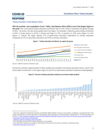
Location 150549/22/2010Close 5054One bushing fails to groundXX23 minutes later, second bushing failsto ground, resulting in phase-phaseground fault (174kA)934NOTE: No tertiary ground detection scheme!9
Location 25034 18:00 Close 307 switches6/15/201518:36:16 Transformer bank energized23 seconds after bank energized, grounddetection bank failed catastrophically18:36:18 Intermittent bank tertiary ground detectoralarms begin18:36:19 Ground detector alarm locked in3-45MVAR,13kV shuntreactors30787418:36:39 Transformer bank trip on three-phasetertiary bus fault (ground detection bank destroyed)XGrounddetection VTsAlarm1hrTrip10
Location 2Click to play video 11
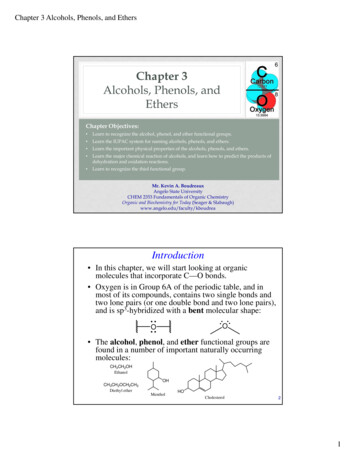
V A V (k V ) V B V (k V ) V C V (k V )IAS( A) IBS( A) IC S( A)Location 2I A S (A )I B S (A )I CS (A )V A V (kV )V B V (kV )V CV (kV )1000500kV currents0-100020VB-n -0-10Tertiary bus voltages (ph-n)0-10-203ph-faultP C T05QD ig it a lsOU T108OU T101V P OLV87R C87R B87R ATR P X FMR051015Cycles202530Initially B-ground fault on tertiary bus59N set for 120V secondary 13.2kV primaryInitial 3Vo measured 230V secondary 25kV primary (bolted)Evolved to catastrophic three-phase fault12
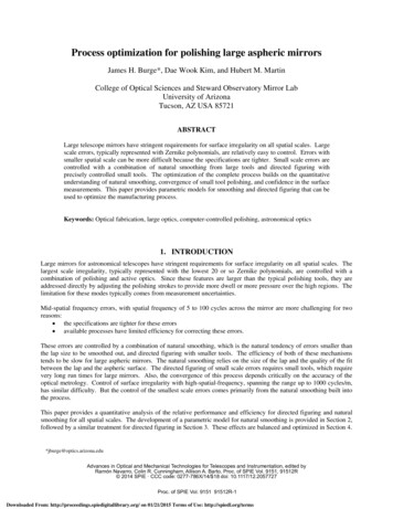
Location 2One of the threefailed VTs307 switchGrounding resistor13
Location 25034Switching as-writtenStep 1: Close 5034Step 2: Close 874Step 3: Close 307 (one switch-at-a-time)3-45MVAR,13kV shuntreactors307874XGrounddetection VTsAlarm1hrTripNOTE: 307 switches are single-phase (two switches per-phase), hotstick operated (one switch-at-a-time)14
Location 32/28/2018 – intermittent fault, no trip8/8/2018@0057 trip!3-45MVAR,13kV shuntreactorsXGrounddetection VTs1hr15 cyclesTrip15
Location 33Vo 13.4kV / 120 112V secondary (3000 ohms)Pickup 100V8/8/2018: All tertiary bus equipment tested, no damage found16
Location 44/30/2019@16:53Ground detection transformers fail, banktrips 15 cyclesB-phase low3-45MVAR,13kV shuntreactorsC-phase low beforetrip (blown fuse)FusesblownXGrounddetection VTsAlarm15 59N set for 94V secondary 11.25kV primary3Vo measured 258V secondary 31kV primary (bolted)Trip17
Location 4Fuses found blownB-phase aux VT shortedprimary-to-secondaryReactor protection control cabinet18
IEEE Guide Search It is “accepted practice” to alarmonly on tertiary bus groundfaults (7.4.2, 7.4.3) Table 4 (9.0) states forMiscellaneous faults that anAlarm may be provided toprovide “sufficient time requiredfor operators to respond” But no mention of what theoperators might actually do whenthe equipment remains energizedwith a standing alarm Quiz – Was this found in:1. IEEE Std C37.234-2009 Guide forProtective Relay Applications toPower System Buses2. IEEE Std C37.91-2008 Guide forProtecting Power Transformers3. IEEE Std C37.109-2006 Guide forthe Protection of Shunt Reactors4. Other?(Do all tertiary buses have shunt reactors installed?)19
Tertiary bus ground detection settings Pickup Time delay Control action (alarm/trip)XAlarmTrip20
Overvoltage pickupFault resistance ( 3Vo mag (kV3Vo mag (voltsprimary)primary)secondary) Consider:022.5375 Bolted fault50016.2270100012.6211 Resistive fault150010.4173 Latest draft C37.234 says 70% of20008.8146value for bolted fault is typical, or25007.6127about 500 ohms coverage for this50004.676scheme75003.355100002.643 NOTE: No need to operate for250001.118double-line-to-ground fault on500000.691000000.35tertiary bus – bank diff will5000000.11operate (or had better!)10000000.00NOTE: The pickup at Location 3 for the 8/8/2018 event where no damage was found: 100V, 30% of bolted, 3000 ohms coverage21
Ground Detection using Three VTs – Resistive SLG faultZsource H ZH-midZL-midZT-midZsource-H ZH-midHLTZH-mid ZL-midZT-midVB3Zf 2270puZf 757puZf 1280 V2LTi0CX0CR/359NV0V1a2V1V1 1.0puV2 -0-puV0 -0.5puVA V1 V2 V0 0.5 puVB a2V1 aV2 V0 1.32 -139 puVC aV1 a2V2 V0 1.32 139 pu3V0 VA VB VC -1.5 puR 3.2 primaryReflects into primary as3.2*(14400/240)2 11.5k R/3 3.84k 2270pu3Zf 2270pui0CVAV0V1XCTXCaV13V0ZL-mid LZT-midZsource0VCX0CR/359NV0 0.5puSo if Vbase 13kVV1 1.0pu 13/ 3 7.5kV3V0 1.5*7.5kV 11250VVT ratio is 14400/240 so relay sees 11250/60 188Vsec22
Ground Detection using Three VTs – DLG faultZL-midZsource H ZH-midZT-midZsource- H ZH-midZL-midLTXCZT-midZL-midZsource0 H ZH-midLTXCZT-midVC aV13V0V1Zeq Zeq-2270pui0CV0 0.5puR/359NV1a2V1V1 0.5puV2 -0-puV0 -0.5puVA V1 V2 V0 0 puVB a2V1 aV2 V0 3/2 -150 puVC aV1 a2V2 V0 3/2 150 pu3V0 VA VB VC -1.5 puLTi0CX0CVBV2X0CV0The negativesequence networkshorts out the highzero sequenceimpedance, leaving asimple voltage dividerV0R 3.2 primaryReflects into primary as3.2*(14400/240)2 11.5k R/3 3.84k 2270puSo if Vbase 13kVV1 0.5pu 6.5/ 3 3.75kV3V0 1.5*13/ 3 11250kVVT ratio is 14400/240 so relay sees 11250/60 188Vsec23
Time delay No coordination issues Set as fast as securely possibleavoiding any unexpectedtransients If resistor continuous rating lessthan power requirement forbolted phase-to-ground tertiaryfault, set shorter than resistorshort-time overload (consultmanufacturer) TVA uses 15 cycles24
Control action – Alarm? Permitted only if resistorcontinuous rating has adequatepower requirement for boltedphase-to-ground tertiary fault Operator expectation? TVA guideline: Deenergize yardbefore allowing operator toinspect25
Control action – Trip Objections1.2.3.4.5.“Practically zero fault current flows,and there is thus no risk of damage.”“Unfaulted phase voltages may rise tofull phase-to-phase voltage, but allequipment should be rated for fullphase-to-phase voltage continuously,so there is thus no risk of damage.”“System operators should have time toplan the loss of the power transformerbank.”“This transformer bank or load is SOimportant that the bank can’t betripped for a ground fault.”“What if nothing is found?”1.2.3.4.5.GrantedTrue – But if insulation failure causedthe first ground fault, applying phasephase voltage across unfaulted phasesmay accelerate failure in those phases(see failures at Locations 1 and 2)Loss of bank for any reason is alreadystudied and mitigated if necessaryIf this is true, all protection shouldalarm and not trip?Possible for any protection systemelement26
Conclusions Two catastrophic events led to an evaluation of tertiary bus grounddetection at 500kV transmission substations and generating plants. TVA has adopted tripping after a short time delay. At stations that still alarm only, yard deenergized before inspection ispermitted. May need additional consideration of required resistive coverage to avoidnuisance tripping for highly resistive ground faults (see Location 3). In light of this “alarming” experience, utilities should review theiroperating and protection practices and philosophy to limit damageand keep personnel safe.27
Questions?28
Presented to 75th Annual Conference for Protective Relay Engineers at Texas A&M University March 27-31, 2022 1. Outline Review -Ungrounded systems Ungrounded tertiary bus ground . 59N set for 120V secondary 13.2kV primary Initial 3Vo measured 230V secondary 25kV primary (bolted) 13 One of the three failed VTs