Transcription
Synthesizable VHDL Models for FSMs, A how-toBy Alan L. Hege, University of North Carolina at CharlotteVHDL is a hardware description language (VHSIC Hardware Description Language (VHSIC – Very High SpeedIntegrated Circuit)). That’s right an acronym within an acronym. It was originally intended to simulate complexlogic systems at a high level. A subset of the instructions can be used to actually describe a logic circuit that canbe physically built from the instructions. The process of converting the code to a circuit implementation is called‘Synthesis’. If the VHDL code synthesized, it is said to be a ‘synthesizable model’. Generally speaking there aretwo forms of modeling within VHDL; (1) the structural model and (2) the behavioral model. The structuralmodel is basically the built up from primitive gate definitions and a net-list (i.e., text description of thecomponents and the way in which they are wired.) Structural modeling is very conducive in describinghierarchal systems. Behavioral descriptions are where the power of VHDL is realized. As the name implies, weare describing the behavior of the circuit using VHDL code.The intention of this document is to allow the student to easily model Finite State Machines (FSM) using VHDL.It is not intended to teach VHDL. We will be using VHDL models of FSMs to create circuits much easier than byhand as already demonstrated in class. The ‘by hand’ method (or manual method) of FSM design consists of (1)creating a State Diagram, (2) determine the State Encoding scheme, (3) filling in the State Transition Table and(4) synthesizing the circuit. With VHDL behavioral modeling we will go directly from a State Diagram to thebehavioral model, then use software to do the synthesis and we’re done.Concurrence:Although VHDL looks like a programming language for a microprocessor, it is not. It has a majordifference all statements are executing at the same time. This property is called ‘concurrence’.Microprocessor code executes sequentially (one instruction after another).
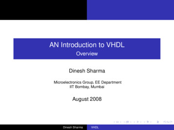
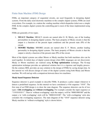
Synthesizable VHDL Models for FSMsTemplates:Many different CAD packages givetemplates as a starting point fordesigning a VHDL module/model. Thefigure to the rightError! Referencesource not found. is a VHDL templatethat is created with Xilinx ISE ProjectNavigator some of the commentlines are removed for conciseness.Format:For the purposes of this class do not modify the ‘library’ and ‘use’ statements shown.The green colored text are comments; they are preceded with two dashes. The blue colored text arereserve words and have a specific meaning within VHDL. The magenta colored text are VHDL definedsignal types. The black colored text are the variable and names the user has given.Under the ‘entity’ line is the ‘Port’ section. The port section defines the port mapping for themodule/model, e.g., it defines the I/O for the module. For this module, the inputs are ‘clk’, ‘I’ & ‘reset’and the output is ‘Z’.Page 2 of 15
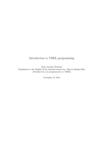
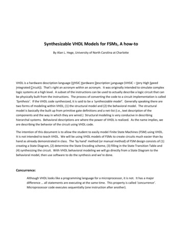
Synthesizable VHDL Models for FSMs1Example FSM:The design methodology will be given via anexample. In this example we will be designing theVHDL behavioral model for a dual edge detectorcircuit (gives a pulse one clock cycle wide on bothedges of the input signal ‘I’). The figure to the rightgives the state diagram for the system.For this design, we will let the Synthesizerdetermine the state encoding or we could force thestate encoding type via CAD software; a tutorialexists for doing this for the Xilinx ISE ProjectNavigator 7.1i software. For ease of coding andsimulation, we will enumerate the states as follows:1S0Z 00S3Z 110S1Z 11S2Z 000Type stateType is (s0, s1, s2, s3);Where ‘stateType’ is a new signal type for ourdesign. Next, we will define the signals for nextstate (ns) and current-state (cs).signal ns: stateType;signal cs: stateType;orsignal cs, ns: stateType;These are considered internal signals to themodule and have a specific location within themodule. Internal signals are defined on thelines between ‘Architecture ’ and ‘begin’ seethe figure to the right.Page 3 of 15
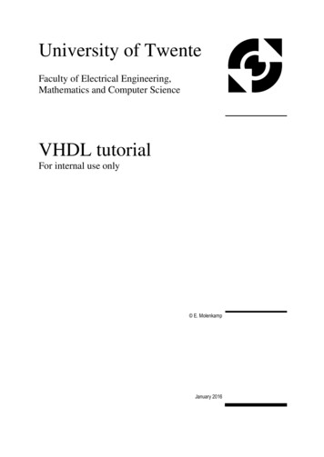
Synthesizable VHDL Models for FSMsNow that the setup is complete we will start coding the blocks in the FSM. Remember that FSMs can bethought of in terms of the following block diagram.(Mealy putLogicZEach block in the state diagram will be coded separately, starting with the Next State Logic block. Thelogic coding resides between the ‘begin’ and the ‘end Behavioral;’ statements.In VHDL, conditional statements like ‘if-then-else’ and ‘case’ statements must be within a ‘process’statement. Process statements have thefollowing format:Process()begin{other VHDL statements}End process;The author usually delineates his blockswith a comment statement ‘—Next-stateLogic Block’. In parenthesis next to theprocess line is the ‘sensitivity list’. Thesensitivity list contains signal names thatwill trigger the process when the signal levelchanges.To the right is the next-state logic block forour design. A lot has changed start bylooking at the key elements of the Processstatement. The main element within theprocess statement is the ‘case’ statement.In the case statement each state isaddressed and the next-state vector (ns) isassigned new values based on the inputs (I).The user can assign new values to signals,multiple times, within a process statement.Page 4 of 15
Synthesizable VHDL Models for FSMsHowever, there can be only one signal source. The process statement counts as one signal source for asignal. For example, the following would not be allowed by the Synthesizer:Process(a)beginif a ”00” theny i0;elsif a ”01” theny i1;elsif a ”10” theny i2;elsey i3;end if;end process;-- process to make a 4-input Mux-- assign value on i0 to the signal yY ‘0’ when reset ’1’ else y yint;-- conditional assignment statementThis code snippet would be incorrect because the signal y has more than one source. Another exampleof too many sources would be as follows:Process(a)beginif a ”00” thenelsif a ”01” thenelsif a ”10” thenelseend if;end process;y i0;y i1;y i2;y i3;Process(b)beginif b ”00” thenelsif b ”01” thenelsif b ”10” thenelseend if;end process;y i0;y i1;y i2;y i3;This snippet would be invalid because each process statement is sourcing y. Multiple sources is notallowed.Now let’s discuss the syntax of the different VHDL statements. First, binary values can be denoted inmultiple ways. For simplicity the author will only discuss std logic formats. Std logic is a VHDL signalPage 5 of 15
Synthesizable VHDL Models for FSMstype. Std logic is a discrete signal type and the values must be written as a one or a zero with singlequotes around the value for example a zero would be ‘0’ and a one would be ‘1’. Strictly speaking thestd logic type has nine possible values: ‘U’, ‘X’, ‘0’, ‘1’, ‘Z’, ‘W’, ‘L’, ‘H’ & ‘-‘. For the scope of thisdocument will only discuss using ‘0’s and ‘1’s. This is mentioned here because the student must knowthat just because something is not a ‘0’ does not mean it is automatically a ‘1’. Another type of signalwe will be using is called the std logic vector. The std logic vector is a bus or ‘bit vector’. Bit vectorvalues must be expressed in terms of one’s andzero’s enclosed in double quotes. For example,the value 3Ah in a 7-bit bus would be expressedas “0111010” in VHDL. The VHDL code snippet, tothe right, would be a VHDL module for assigningthe value 3Ah to a 7-bit vector z.Notice the double quotes around the binaryvalue. Also, notice the port-map for the moduleStd logic vector(6 downto 0)This defines the signal z as being an array ofsignals having indexes from 6 to 0; 6 in this case isthe msb and 0 is the lsb. Treating bus membersas individual signals would be performed asfollows: z(6) 0, z(5) 1, z(4) 1, z(3) 1, z(2) 0,z(1) 1, & z(0) 0. For a better understanding ofhow bit vectors (busses) work in VHDL, consider shifting z in the above example left one bit and theshift- in value would be a one:z1 z(6 downto 1) & ‘1’;The ampersand (&) is the operator for concatenating two vectors. The new value z1 would now containthe value “1110101”. Of course, more would need to be done to the module above in order for thisvalue to have any meaning (not produce an error). For instance, the user would need to define thesignal. If it were an internal signal then the signal definition, placed between the ‘architecture ’ lineand the ‘begin’ statement would need to be:signal z1: std logic vector(6 downto 0);Back to the example FSM, within the case statement were If-then-else statements. See Appendix A forthe various syntax forms. If-the-else statements can only appear within process statements. If-thenelse and case statements can be nested for complex logical behavior.Page 6 of 15
Synthesizable VHDL Models for FSMsState Memory Block:The state memory block is nothing but a register. This can be defined with a process statement that hasclk as the sensitivity list as follows:process(clk)beginIf clk’event and clk ’1’ thenQ D;end if;end process;In this process clk is examined and on the rising edge the value on D is assigned to Q. D and Q could be abus in which case this would be a register or D and Q could be discrete signals in which case this wouldbe a D-type flip-flop. For a negative edge, the conditional part of the if-then-else statement would be:If clk’event and clk ’0’ thenQ D;end if;This could be read as “when the clock changes and the new value is zero then assign D to Q” e.g., onthe negative edge. Other variations would be when a reset is present. For an asynchronous reset:process(reset, clk)beginif reset ’1’ thencs s0;elsif clk’event and clk ’1’ thencs ns;end if;end process;Page 7 of 15
Synthesizable VHDL Models for FSMsReset is active-high and the register is called cs (current state). Notice reset is independent of the clk definition of asynchronous. The following snippet would be used if a synchronous reset (clear) isrequired:process(reset, clk)beginif clk’event and clk ’1’ thenif reset ’1’ thencs s0;elsecs ns;end if;end process;For this example, an asynchronous reset is required. See the figure below for the state memory blockdesign solution.Page 8 of 15
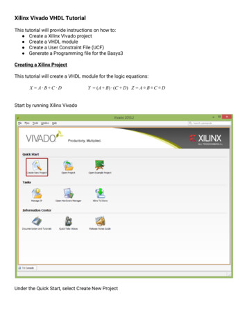
Synthesizable VHDL Models for FSMsOutput Logic Block:1As a reminder of the state diagram it is shown again here to analyze theoutput logic. Here we see that the output z is true when in states s1 &s3. The following concurrent statements could be used:Z ‘1’ when cs s1 or cs s3 else ‘0’;orwith cs selectZ 100S3Z 11‘1’ when s1 s3,‘0’ when others;S0Z 0S1Z 11S2Z 000If the outputs are more complicated, then a process statement could be used. Note in the last statement thereserve word ‘others’ is used. It means to assign zero to Z when anything other than s1 and s3 are the values ofcs.This project synthesized without any errors. Within Xilinx Project Navigator you can examine the consolewindow, after the module was synthesized, and discover that grey code state encoding was used. This wasdetermined by the software notice in the design that we did not assign values to the states (s0, s1, s2 & s3).There are ways to force the synthesizer to use a specific state encoding scheme and they are covered in atutorial (located at http://www.coe.uncc.edu/ alhege/Xilinx Tutorials/Misc Tutorials/Xilinx FSM notes.pdf).Page 9 of 15
Synthesizable VHDL Models for FSMsAppendix A: VHDL Syntax (abridged)Defining signals:I/O ports on for the modules are created by Xilinx ISE Project Navigator Wizard for VHDLmodule creation.Internal signals (between ‘Architecture ’ line and ‘begin’ line):oConstant declaration and value assignment:Constant MAXCOUNT: std logic vector(7 downto 0) : “10101010”oDiscrete signal:signal reset: std logic;oBus:signal kount: std logic vector(31 dowto 0);oEnumeration:type sType is (init, firstState, secState, s3, wait);oUse of enumerate type above:signal d: sType;Relational Operators (conditional operators):‘ ’ – equals‘/ ’ – not equals‘ ’ – greater than‘ ’ – greater than or equal‘ ’ – less than‘ ’ – less than or equalPage 10 of 15
Synthesizable VHDL Models for FSMsAssignment Statements:Signal-name expression;Conditional Assignment:signal-name expression when boolean-expression elseexpression when boolean-expression else expression when boolean-expression elseexpression;Selected signal-assignment:with expression selectsignal-name signal-value when choices,signal-value when choices, Signal-value when choices;Example:with N selectF ‘1’ when “0001”,‘1’ when “0010”,‘1’ when “0011” “0101” “0111”,‘1’ when “1011” “1101”,‘0 when others;Page 11 of 15
Synthesizable VHDL Models for FSMsConditional Statements:If-then-else:oif boolean-expression then sequential-statementsend if;oif boolean-expression then sequential-statementselse sequential-statementsend if;oif boolean-expression then sequential-statementselsif boolean-expression then sequential-statements elsif boolean-expression then sequential-statementsend if;oif boolean-expression then sequential-statementselsif boolean-expression then sequential-statements elsif boolean-expression then sequential-statementselse sequential-statementsend if;case:ocase expression iswhen choices sequential-statements when choices sequential-statementsend case;Page 12 of 15
Synthesizable VHDL Models for FSMsAppendix B: Synthesizable VHDL Behavioral Model SkeletonDeclaration - States:Architecture Behavioral of FSM name istype sType is (init, s1, s2);signal cs, ns: sType;begin{{{model body}}}End Behavioral;Model Body – Next-state Logic Block:process(cs, {inputs})begincase cs iswhen init {{{next-state options}}}when s1 {{{next-state options for s1}}}when s2 {{{ next-state options for s2}}}when others {{{next-state options for everything else}}}end case;end process;Page 13 of 15
Synthesizable VHDL Models for FSMsModel Body – State Memory block:Basic register ns is D and cs is Q (rising-edge triggered):process(clk)beginif clk’event and clk ‘1’ thencs ns;end if;end process;Basic register (trailing-edge triggered):process(clk)beginif clk’event and clk ‘0’ thencs ns;end if;end process;Register w/ Asynchronous reset:process(clk, reset)beginif reset ’1’ thencs init;elsif clk’event and clk ‘1’ thencs ns;end if;end process;Page 14 of 15
Synthesizable VHDL Models for FSMsRegister w/ async reset and clock enable(CE):process(clk, reset, CE)beginif reset ‘1’ thencs init;elsif clk’event and clk ‘1’ and CE ‘1’ thencs ns;end if;end process;Register w/ synchronous reset and clock enable(CE):process(clk, reset, CE)beginif clk’event and clk ‘1’ thenif reset ‘1’ thencs init;elsif CE ‘1’ thencs ns;end if;end if;end process;Model Body – Output Logic Block:Use Simple Assignment, Conditional Assignment, Selected Signal Assignment or any combination ofthese statements or combo with the following.Use a process statement where outputs may be dependent on the inputs (case, or if-then-else).Page 15 of 15
Synthesizable VHDL Models for FSMs, A how-to By Alan L. Hege, University of North Carolina at Charlotte VHDL is a hardware description language (VHSIC Hardware Description Language (VHSIC – Very High Speed Integrated Circuit)). That [s right an acronym within an acronym. It was originally