Transcription
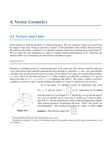
TIP 0425-03ISSUED – 2016 2016 TAPPIThe information and data contained in this document wereprepared by a technical committee of the Association. Thecommittee and the Association assume no liability or responsibilityin connection with the use of such information or data, includingbut not limited to any liability under patent, copyright, or tradesecret laws. The user is responsible for determining that thisdocument is the most recent edition published.CAUTION:This Technical Information Paper may require the use, disposal, or both of chemicals which may present serious health hazards to humans.Procedures for the handling of such substances are set forth on Material Safety Data Sheets which must be developed by all manufacturers andimporters of potentially hazardous chemicals and maintained by all distributors of potentially hazardous chemicals. Prior to the use of thistechnical information paper the user should determine whether any of the chemicals to be used or disposed of are potentially hazardous and, if so,should follow strictly the procedures specified by the manufacturer as well as local, state, provincial, and federal authorities for safe use anddisposal of these chemicals.Design, monitoring and maintenance guidelines forYankee dryer bearingsScopeThis document is intended to provide general guidelines for Yankee dryer bearings regarding design,monitoring, maintenance, and operation.IntroductionYankee dryer bearings are critical to the safe and reliable operation of the paper machine. The degree of timeand expense spent on monitoring and maintenance of the bearings represents a fraction of the cost of a failure.Improved bearing designs as well as advanced techniques for inspection and maintenance have resulted in fewerbearing failures. These guidelines represent a compilation of information from various equipment suppliers and endusers.Since Yankee dryer bearings operate at different speeds, on a variety of different sized dryers (both diameterand width) and different dryer materials (cast iron vs. steel), universal procedures are not practical. The followingguidelines for safe, reliable, and economical operations must be considered along with the mill’s experience, the ageof the equipment, and the knowledge of the bearing design. Bearing monitoring criteria will evolve over time as themill gains the experience.DesignReliable Yankee bearing operation starts with a sound design. Some of the key components in the design ofthese large bearings are the L10 design life, the bearing housing, housing seals and journal insulation.Yankee dryer bearing design lifeWhen calculating the life of Yankee dryer bearings, it is recommended that both L10h and L10ah are taken intoconsideration. The L10ah bearing life equation, takes into account the influence of possible lubrication problems inthe calculated L10h life. Both of these calculated lives should exceed 200,000 hours.and𝐿𝐿10ℎ1 000 000 𝐶𝐶 𝑝𝑝 60 𝑛𝑛𝑃𝑃TIP Category: Automatically Periodically Reviewed (Five-year review)TAPPI
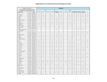
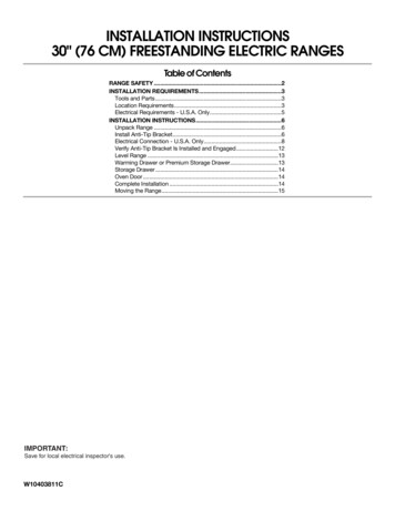
TIP 0425-03Design, monitoring and maintenance guidelines for Yankee dryer bearings / 2𝐿𝐿10𝑎𝑎ℎ 𝑎𝑎23 𝐿𝐿10ℎL10h basic rating life, operating hoursn rotational speed, r/minC basic dynamic load rating, N (or lbs.)P equivalent dynamic bearing load, N (or lbs.)p exponent of the life equationp 3 (ball bearings)p 10/3 (roller bearings)L10ah adjusted rating life, operating hoursa23 combined factor for material and lubricationYankee dryer bearings are exposed to very high temperatures over long periods of time. Unfavorablelubrication conditions are quite common and short start-up periods cause very high thermal stresses in the bearings.Experts use computer programs to analyze an application based on the influence of the internal design of thebearing, clearance reduction, axial preloading, bearing temperatures and lubrication requirements.The selection of material and heat treatment has to be based on some estimates as well as on several knownparameters and serves to minimize the risk of cracked bearing inner rings. The following parameters should be takeninto account: The residual stress of the inner ringThe maximum difference between the temperatures of the journal inner ring and the outer ringThe drive-up of the bearing (see Installation and Replacement Procedure below)The initial radial internal clearance of the bearingThe ability to rapidly detect damage to the inner ring and take action to prevent crackingFor paper machine and Yankee dryers, special steel or case carburized steel inner rings are used for betterresistance to through cracking, wear and fatigue. In cases where journals are not insulated and have steamtemperatures above 170 C (338 F), bearings with case hardened inner rings are recommended.Yankee dryer bearing housingYankee cylinder housings are available in the following basic arrangements: Front side: CARB toroidal roller bearing with located outer ring (Fig. 1)Front side: spherical roller bearing with non-located outer ringFront side: spherical roller bearing with located outer ring in housing on rockers (Fig. 3)Note: This arrangement may include linear ladder bearings to prevent machine-direction movement whileallowing necessary axial movement Drive side: spherical roller bearing with located (held) outer ring or outer race (Fig. 2)Yankee dryers are typically carried by spherical roller and CARB (compact aligning roller bearing) toroidalroller bearings mounted directly on tapered journals or on adapter sleeves. If the bearings are to be mounted ontapered seatings, the journals should be provided with oil injection grooves to facilitate dismounting of the bearingsand adaptor sleeves.
3 / Design, monitoring and maintenance guidelines for Yankee dryer bearingsFig. 1: CARB toroidal bearingTIP 0425-03Fig. 2: Spherical roller bearingFig. 3: Tending side Yankee dryer bearing with rocker/ ladder housingSplit bearing housings with removable covers on both sides are normally used. The split cover at the insideposition provides easy inspection, mounting, and dismounting of the bearing.Before the introduction of CARB toroidal roller bearings, there was a need to have special front sidehousings for spherical roller bearings. These housings are provided with rockers in order to accommodate axialloads on the bearings and the frame caused by thermal expansion of the Yankee dryer. They also have anchoringhooks in order to keep the bearing housing in position when the cylinder is being pressed upwards by the pressureroll(s). It is necessary to equip the front side bearing housing with rockers in the horizontal plane if the pressure rollsare located in such a position that the resultant load (including gravity forces) on the cylinder diverges more than30 from the vertical downward position.Today, the use of CARB toroidal roller bearings on the front side is recommended. The CARB toroidalroller bearing eliminates the need for the rocker housings, as the bearing itself will accommodate the thermalexpansion of the Yankee dryer. Instead, the bearing can be mounted in a more robust and rigid, fixed housing. Thisgives a more stable arrangement and reduced vibration level which is especially important at increased speeds.Lower vibration level also means less risk of component wear.
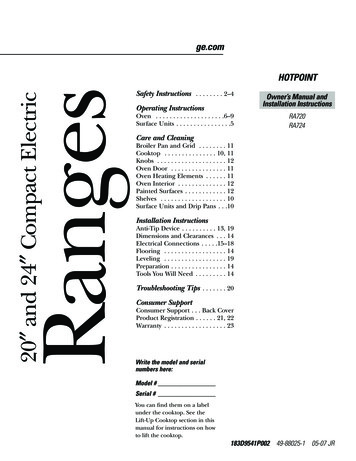
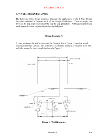
TIP 0425-03Design, monitoring and maintenance guidelines for Yankee dryer bearings / 4Housing SealsA very important factor for the reliable functioning of bearings in paper machines is efficient sealing of thebearing arrangements. It is important that sealing arrangements adequately protect the bearings from contaminationand also prevent the lubricant from escaping and running down the machine.A rolling bearing contaminated by water and/or solid particles will become unserviceable long before itscalculated life has been attained. When designing seals, consideration must be given to the environment of eachspecific bearing arrangement. The bearing arrangements may be subjected to flowing water, condensation, dryconditions, or a high ambient temperature, depending on where in the machine they are positioned.The seals of the housings on the non-locating side must allow for the required axial movement. The basicdesign of the seal depends upon whether the bearings are lubricated by grease or oil. The figures below show someexamples of basic designs of bearing arrangements. Different types of sealing arrangements are shown in thelubrication examples.The need for efficient seals is greatest in the wet section where most of the bearing arrangements aresubjected to very wet conditions. Experience shows that a well-greased multi-stage labyrinth seal, whether it is axialor radial, affords good protection of the bearings in the wet section especially when it is reinforced by a splash guard(Fig. 4).If the bearings are oil lubricated, the sealing arrangements have to be of a different design. Fig. 5 shows anefficient seal for oil lubricated press roll bearings. The seal must prevent water from entering the bearing housing,even during hosing down, which is often carried out with water at high pressure.In the dryer section of the machine, the bearing housings are exposed to moisture in the form of condensationor leaks from steam nozzles etc. Paper fibers may enter the housings too. Nevertheless, simpler seals may be usedfor the housings in the dryer section. However; if problems occur, more efficient seals have to be applied. Fig. 6shows a proposal of how to improve the seals of dryer section housings.Fig. 4: Multi-stage labyrinthseal with grease lubricationand splash guardFig. 5: Labyrinth lip seal foroil lubricationFig. 6: Modified labyrinthseal for dryer housingAn insulating sleeve shields the journal from the steam by creating an air gap that serves as an insulatingbarrier to reduce the heat transfer into the journal and the bearing. There are different designs for how this sleeve inmounted and sealed on the end. It is common that a weep hole exists to alert personnel that the seal and theinsulating air gap has been compromised. In such cases, a repair plan should be developed and executed at the nextmaintenance opportunity. Improperly maintained sleeves may result in premature bearing failure and place anadditional heating load on the bearing lubrication system. If this heat transfer results in excessive bearing and oiltemperatures, oil and oil additive degradation is accelerated. High temperatures can negatively affect viscosity andcause oil films to collapse and accelerate abrasion and scuffing conditions. The insulating sleeve assembly includesthree parts: the sleeve itself, the inboard seal and the outboard seal (Fig. 7).Sleeve – can be a single (or double) walled tube with or without insulation wrapped around the outside. (A doublewalled tube cannot include a vent and should be inspected every 5 years).
5 / Design, monitoring and maintenance guidelines for Yankee dryer bearingsTIP 0425-03Inboard Seal – can be formed from a slip fit, o-ring & gasket or simply a gasket.Outboard Seal – can be formed from a gasket, O-ring or stuffing box.SleeveOutboardSealInboardsealFig. 7: Yankee dryer journal with insulating sleeveExpansion – each sleeve assembly allows for one end to expand as the dryer temperature increases through a slip fit,o-ring, gasket or stuffing box.Older Yankee dryers built in the 1960’s and 1970’s included insulation wrapped, single walled tube sleeveswithout an inboard seal (only a tight tolerance slip fit) and with a gasketed flanged outboard seal. Yankee dryersmanufactured between 1980 and 1996 included uninsulated, single walled tube sleeves with o-ring and gasket orgasketed flange for the inboard seal and o-ring outboard seal. Yankee dryers built after 1997 included uninsulated,single walled tube sleeves with a gasketed flange for the inboard seal and stuffing box outboard seal.Vent – tapped into the insulating cavity is used to provide an early indication of a leaking seal or cracked sleeve.Inspection – external visual inspection of the vent on a single walled tube can be done frequently. In general theinsulating sleeve should be inspected inside and outside the dryer as part of the scheduled Yankee dryermaintenance program or every 5 years. Replace gaskets and packing.Installation and replacement procedureYankee dryer manufacturers typically have a carefully engineered procedure for lifting the dryer duringbearing changes. Key objectives are to make a safe lift without damaging the Yankee while providing preciseposition control for bearing installation. Most often this includes a cradle arm under the journal. An idealarrangement includes lifting jacks on both sides of the cradle to provide elevation and some MD control of theYankee centerline. It is possible to lift a Yankee on the shell, but loads should be applied at the head area with aproperly designed cradle. Caution should be taken to prevent CD movement on the tending side CARB bearingwhen lifting the drive side of the dryer. Positive blocks placed between the dryer head and the support frame willsecure the dryer CD position.There are typically two methods for mounting Yankee dryer bearings on a tapered journal bearing seats;Clearance Method and SKF Axial Drive-Up Method. Each method assumes the journal bearing seat taper andsurface are within specification. (See bearing manufacture’s specifications) Surface contact of the journal with thebearing bore is recommended to be 80%. Also, the bearing temperature should be within 5.5 C (10 F) of theYankee dryer journal temperature it is to be mounted on. Always inspect the bearing for storage or transportationdamage before installation. Contact a bearing manufacturer’s field engineer for assistance with Yankee dryerbearing mounting and setup.Mounting: Clearance MethodThe internal clearance of a bearing is the total distance through which one bearing ring can be moved relative to
TIP 0425-03Design, monitoring and maintenance guidelines for Yankee dryer bearings / 6the other. Movement in the radial direction is called “radial internal clearance;” axial movement is called “axialinternal clearance.”Clearance before and after mounting – It is important to distinguish between the internal clearance of a bearingbefore mounting and the internal clearance of a mounted bearing under actual operating conditions. Clearancebefore mounting is usually greater than the operational clearance because the rings expand or compress due tothe interference fit, and because of thermal expansion of the bearing rings and associated components.Measuring clearance with a feeler gauge - A feeler gauge is most often used to measure the radial internal clearancein medium-size and large spherical roller bearings and CARB toroidal roller bearings, before, during andafter mounting. (Fig. 8 and Fig. 9)Before measuring, rotate the inner or outer ring a few times. Make sure that both bearing rings and the rollercomplement are centrically arranged relative to each other.Fig. 8: Clearance measuredwith feeler gaugeFig. 9: Measure radial andaxial clearanceTo start, select a feeler gauge blade that is slightly thinner than the minimum value for initial bearingclearance. When measuring, move the blade back and forth between the middle of the roller and raceway. Repeatthis procedure using a thicker blade each time until you can feel a slight resistance between the blade and roller. Toconfirm the value, rotate the inner ring 180 degrees and measure again. Take measurements between: The outer ring and uppermost roller, before mounting (Fig. 10a) The outer ring and lowest roller, after mounting (Fig. 10b)Use the bearing manufacturer’s recommended clearance reduction amounts when mounting the bearing.Fig. 10: Bearing clearance measurements
7 / Design, monitoring and maintenance guidelines for Yankee dryer bearingsTIP 0425-03For large bearings, especially those having a rather thin-walled outer ring, the measurements are affected bythe elastic deformation of the rings, caused by the weight of the bearing or the force to draw the feeler gauge bladethrough the gap between the raceway and an unloaded roller. To establish the “true” clearance before and aftermounting, use the following procedure (See Fig. 11):a)b)c)Measure the clearance “c” at the 12 o’clock position for a standing bearing or at the 6 o’clockposition for an unmounted bearing hanging from the shaft.Measure the clearances, “a” at the 9 o’clock position and “b” at the 3 o’clock position, withoutmoving the bearing.Obtain the “true” radial internal clearance with relatively good accuracy from:True value 0.5 (𝑎𝑎 𝑏𝑏 𝑐𝑐)(a)Fig. 11: Measuring large bearings(b)Mounting: SKF Drive-up MethodWhen mounting tapered bore spherical roller bearings and CARB toroidal roller bearings on dryingcylinder journals, the use of the SKF Drive-up Method is strongly recommended. This is a more precise and lesssubjective method than measuring clearance reduction with feeler gauges. Contact SKF for suitable tool kits for thismounting method (Fig. 12).Starting position – In order to obtain reliable drive-up measurements, the influence of form errors must be reducedto negligible proportions. This can be done by driving the bearing up, passing the indeterminate zero positionto a starting position that corresponds to a certain small initial interference. Above this initial interference,reduction in the radial internal clearance may be regarded as being directly proportional to the axial drive-up(Fig. 13).Note: Pressurized oil must not be injected to the mating surfaces before the starting position is reached.Axial drive-up from the starting position - The axial drive-up is best monitored by a dial indicator connected to ahydraulic nut. If pressurized oil has been injected to the mating surfaces during the drive-up, wait a fewminutes before releasing the hydraulic nut pressure so that the oil can drain from the surfaces.
TIP 0425-03Design, monitoring and maintenance guidelines for Yankee dryer bearings / 8Fig. 12: Drive-up tool setupFig. 13: Drive-up positionsSpherical roller bearingsa)b)c)d)e)f)g)h)i)j)k)l)Lightly oil the mating surfaces with a thin oil.Carefully position the bearing in the housing and on the shaft.For housings bolted to the frame (or frame housings): Check that all rollers are unloaded, i.e. the shaft mustbe centered in the housing during the drive-up.For housings disconnected from the frame: Lift the shaft with bearing and housing about 5 mm (0.20”) andcheck that the housing is free to move axially.Drive the inner ring up to the starting position.Drive the inner ring up the taper the required distance Ss 5% (wait a few minutes before releasing thehydraulic nut).If the housing has been disconnected, bolt it to the frame.Check the housing alignment, e.g. shaft centered relative to the inner cover.For front side housings bolted to frame: Check the axial position of the housing.For front side housings on rockers: Check the position of rockers and base plate.If necessary, adjust the position of the housing/rockers/base plate (refer to OEM recommendations orspecifications).The SKF software program “SKF Drive-up” can be used for calculations. Note that the drive-up valuesobtained are only valid for SKF bearings. For more information on the Drive-up Method and its use withnon-SKF bearings, contact SKF Engineering.CARBTM toroidal roller bearings1)2)3)4)5)6)7)8)9)10)Lightly oil the mating surfaces with a thin oil.Carefully position the bearing in the housing and on the shaft.For housings bolted to a frame: Check that all rollers are free to move throughout the drive-up process.For housings disconnected from the frame: Lift the shaft with bearing and housing about 5 mm (0.20”) andcheck that the housing is free to move axially.Drive the inner ring up to the starting positionDrive the inner ring up the taper the required distance Ss 5% (wait a few minutes before releasing thehydraulic nut).If the housing has been disconnected, bolt it to the frame.Check the housing alignment, e.g. shaft centered relative to the inner cover.Check that the axial displacement of the inner ring (relative to outer ring) is within specified values.If necessary, adjust the position of the housing (refer to OEM recommendations or specifications).The SKF software program “SKF Drive-up” can be used for calculations. Note that the drive-up valuesobtained are only valid for SKF bearings. For more information on the Drive-up Method and its use with non-SKFbearings, contact SKF Engineering.
9 / Design, monitoring and maintenance guidelines for Yankee dryer bearingsTIP 0425-03LubricationA separate circulating oil lubrication system is recommended for the Yankee cylinder bearings. Owing to thehigh temperature of the steam, large quantities of oil of appropriate viscosity must be passed through the bearings toachieve proper lubrication. Many factors influence the calculation of the requisite oil flows, so these must bedetermined for each individual case. Consideration should be given to bearing size, speed, steam temperature, oilinlet temperature and journal insulation method. The influence of bearing load and ambient temperature on thetemperature of the Yankee cylinder bearings is small compared with that of the speed, steam temperature andinsulation method.Oil filmsLubrication plays a major role in rolling bearing performance. The main task of the lubricant is to build up anoil film between the rolling elements and the raceways. The oil film should be thick enough to separate these matingsurfaces completely. The film thickness in a rolling bearing is dictated by the bearing size, the operating speed andthe viscosity at the operating temperature of the oil used; the higher the speed, the thicker the oil film.Typical film thickness for Yankee dryer bearings is 0.20 micron (7.9 x 10⁻⁶ in.).Low speed operationA sufficient oil film cannot be established in the bearings when operating the Yankee dryer at low speed.Brief operation (1-2 hours) has been found to be tolerable. However longer slow speed operation necessary during adryer grind requires more attention to the bearing lubrication. Special precaution must be taken to ensure everythingpossible is done to protect the bearings. Consult with your lubrication and bearing representative to develop aproven method based on specific conditions to protect the Yankee bearings during slow speed operation.Basic termsWhen selecting suitable lubrication for rolling bearings, there are some basic terms that need to be known:Kinematic viscosity - The kinematic viscosity describes the resistance to flow of the oil at a certain temperature. Lowvalues mean that the oil flows easily; high values mean that the oil flows sluggishly. The unit for viscosity ismm2/s (previously known as Centistoke).Viscosity index - The viscosity of an oil changes with the temperature. The viscosity index is a way to describe themagnitude of the change for a specific oil. Synthetic oils normally have a much higher viscosity index thanmineral oils, i.e. their temperature dependence is less.Bearing life factor - The bearing life adjustment factor will either increase or decrease the calculated bearing lifebased on the additives in the oil.Different types of additivesProduction of all different lubricating oils begins with a straight base oil. The difference between hydraulic,gear, engine and paper machine oils is the combination of different additives mixed into the base oil. Below areexplanations of the functions of some common additives in paper machine oils.Anti-corrosion - Both water soluble and oil-soluble chemicals are used to provide sufficient protection in dampoperating conditions.Anti-foam - The foam-damping action can be obtained, for example, by adding small quantities of silicone fluid.Such additives cause the bubbles to burst when they come in contact with the surface of the oil in thereservoir. Air in the oil gives shorter oil and bearing life.
TIP 0425-03Design, monitoring and maintenance guidelines for Yankee dryer bearings / 10Anti-oxidant - Oil exposed to high temperatures and air oxidizes forming compounds. These compounds canincrease the viscosity of the oil and also cause corrosion. Viscosity increase is normally used as one criterionfor oil change because these oxidation compounds have a negative influence on the lubrication effect. Antioxidants improve the oxidation stability of the oil by 10 to 150 times.EP (extreme pressure) - If the oil film in the rolling contact is not thick enough to fully separate the surfaces, therewill be an interaction between the mating surfaces causing very high local temperatures. The temperature canbe so high in these hot spots that asperities are welded together. This creates high friction and heavy adhesivewear like smeared surfaces in the bearing. EP additives cause a chemical reaction in any hot spots so that theasperities shear off instead of being welded together. The result is a smoothing effect which reduces the sizeof surface irregularities. After some time, the surfaces should be fully separated by the oil film.AW (anti-wear) - At temperatures above 80 C (176 F) where EP additives should not be used, AW additives arerecommended to reduce the risk of wear and smearing in the bearing. Additives of the AW type form asurface layer with certain beneficial properties such as a stronger adhesion to the surfaces. This surface layercauses the asperities of the mating surfaces to slide over each other instead of shearing off.Detergent - These additives may be described as “cleaning” additives. They work in such a way that reactionproducts from high-temperature zones are kept floating in the oil. Without these additives, such reactionproducts may adhere to and discolor the surfaces in contact with the oil. These additives are normally used inengine oils for cars and are not recommended for paper machine bearings.Dispersant - One way to avoid sedimentation of contaminant particles inside the long pipes and large reservoirs ofpaper machine lubrication systems is to use an oil with dispersant additives. These additives can keep theparticles floating in the oil until they enter the oil filter. One drawback of these additives is that they can keepsmall drops of water floating as well. This may cause corrosion in the bearings and clogging of the oil filters.Another drawback is that these additives can neutralize the effect of anti-wear additives.Viscosity-improvement - These viscosity increasing additives are often made up of large-molecule polymers.Additives of this type are not recommended for paper machine oils.Oil cleanlinessLubricating oil should be continuously cleaned of impurities. It is important to remove both water and solidparticles from the oil. When selecting suitable water extractors and filters, the following cleanliness guidelinesshould be aimed for:a)b)Water content should be below 200 ppm.Particle content should be according to ISO 4406 cleanliness class –/15/12 (using a microscope) or18/15/12 (using automatic particle counter) or SAE class 6B/6C, or better. The recommended watercontent level can be obtained by using ordinary extractors (dehydrator devices or centrifuges)available on the market.Oil filtersDifferent types of oil filters have been used for many years in the lubrication systems of paper machines. Thefirst replaceable filters were so-called mesh elements made of woven steel wire. These filters were efficient when itcame to very large particles, but research has proven that even particles smaller than 10 μm should be removed fromthe oil because they may have a detrimental effect on bearing surfaces. There is a definitive connection between finefilters, clean oil, and the life of Yankee dryer bearings. The recommended particle size is 5-6 microns. New oilshould be filtered before placing in reservoir.
11 / Design, monitoring and maintenance guidelines for Yankee dryer bearingsTIP 0425-03Preventative maintenanceMonitoringContinuous monitoring of the Yankee dryer bearings is the most dependable way to ensure reliable operationand long life. Monitoring the bearing temperature, lubrication and vibration is the best way to gauge the bearingcondition and prevent failure.Temperature Monitoring - Temperature sampling and analysis can be taken either electronically or physically.Electronic offers the real time value of immediate notification and trending capabilities through the papermachine DCS systems. Temperatures are generally taken through use of housing ports designed to acceptprobes or through external contact devices. Probes are generally more reliable and tend to reflect the actualbearing temperatures of the outer races. Once taken and electronically submitted to the DCS systems, theyare compared to a range with upper and lower limits with associated alarming - visual, auditory, or both fromthe operators control station.Another method of temperature monitoring is through lubrication medium monitoring. Lubrication oils aregenerally both heated and cooled depending on the location of the mill, the system within the mill and on the typeand size of bearing being lubricated. Yankee dryer bearing lubrication temperature recommendations depend onoperational factors pre-determined by the bearing OEM, but generally will be in the range of 60 C (140 F) on thesupply side of the bearing housing. Oils are either heated or cooled to maintain this temperature. Differentialtemperatures across Yankee dryer bearings should be in the range of 11 C to 19 C (20 F to 35 F). Differentialsoutside of these parameters generally point to a failure in the bearing or bearing mount and/or the bearing lubricationsystem.Lubrication Monitoring - Through careful lubrication sampling and analysis, the life blood of the bearings can beboth physically and chemically tested to determine wear progression, contamination, and conditionbreakdown. Lubrication sampling must be rep
Design, monitoring and maintenance guidelines for Yankee dryer bearings . Scope This document is intended to provide general guidelines for Yankee dryer bearings regarding design, . single walled tube sleeves with o-ring and gasket or gasketed flange for the inboard seal and o-ring outboard seal. Yankee dryers built after 1997 included .