Transcription
Hygienic Design Standards and GuidelinesLarry Hanson
Key Cleanability Design Considerations Material of Constructions Surface Finishes Joint Design No Cracks or Crevices Free Draining No Dead Legs – Blind Spots - Hollows Accessibility to Clean Accessibility to Inspect
“Sanitary Design for Beginners”4
Metals Appendix 1 Stainless Steels Wrought 304 and 316Non-GallingPrecipitation HardenableDuplexSuperausteniticNickel-Chromium – Molybdenum Alloys Titaniums
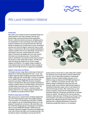
304 & 316 Stainless Steel
Non-Gallingprevents damagefrom moving partswear
Other Metals Aluminum – Limited application in 3A standards Brass-Bronzes No acceptable 3-A applications Coppers No acceptable 3-A applications
Non-Metals Plastics Elastomers -Rubber and Rubber like Material Carbon and Ceramic Glass Must meet FDA requirements Must not chip, crack, or have crevices
How to select and obtain approval of plastics
Surface Finish Product Contact Surfaces At least a smooth as 32 µin Ra (0.8 µm) allsurfaces Including welded, soldered and brazed joints Free of pits, folds, cracks, crevices andmisalignments 2B finish is generally acceptable, but needsverification Inside tubing welds shall be full pentration andmeet the color criteria as specified in AWSD18.2
Surface Finish Non-Product Contact Surfaces “Exposed surface shall have relatively smooth surfacesand be relatively free of pockets and crevices where soilsand liquid can collect” A crevice or pocket in a weld would be structural defectand would require repair Welds are not required to be ground or polished. Blasting or other surface treatments that reduce surfacefinish of the base material should not be preformed
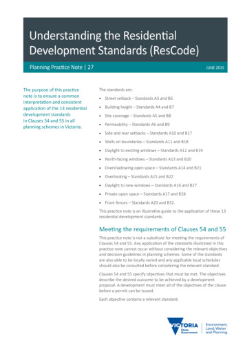
Surface Roughness Measurement Specify on Drawing, Specification and ProposalMeasure with ProfilometerMeasure Across the GrainOptical Comparators
Measurement with Profilometer
Surface Treatments
Hands on experience with surfaces finish.
Joint Design – Product Contact Permanent Joints Welded –MetalsWelded –Thermoplastics (Permitted only by specific standards)Solder and Brazing (Permitted only by specific standards)Interference Fits –Metal to MetalBonded Joints(Permitted only by specific standards) Non Permanent Joints Mechanical Forced SealsGasketed Joints for Sanitary FittingsFlat Gasket must be substantially flushSeal in Series with
Welded Joints Must continuously welded Must meet surface finish requirements statedearlier Meets Criteria of AWS D18.1, D18.2, and D18.3
No skip or stich welds
Sanitary Tubing Welding Full Penetration No Pits, Cracks, and Crevices
Incomplete Weldin Hollow Tube
Interference Joints Metal to Metal Joints Only Free of External Shoulders Free of Relieved Area Permitted by Specific 3-A Equipment Standards Tightness of Fit shall be validated no liquid migration EHEDG Guideline 2 Testing Procedure Pass Dye Penetrant Test
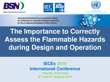
Acceptable – Interference Fit Designs
Un-acceptable Interference Fit Designs
Draining All Product Contact Surface shall be self-draining Except for typical clingage and adherence All Non-Product Contact Surfaces designed to minimize pooling Liquids cannot drain into product or product contact surfaces Product and solution tubing should pitch 1/8 inch/ft minimum Flat surfaces should pitch ¼ inch/ft minimum
Pooling is a source ofcontamination in PCS and NPCS
Pans need to drain way from Product Contactsurface
Dead Legs – Hollows - Blind spots Avoid dead legs in hollow that may not clean Avoid hollow roller that create niches Avoid hollow frame construction Avoid blinds spot that are hard to clean and inspect
Hollow RollersAll rollers should be solid withbearings outside the productzone
Hollow roller identified during design review
Hollow TubingFrame
Hollow TubeFrame VS OpenAngle Frame
Radii All angle less than 135⁰ shallhave radii of at least ¼ inch Exception for gaskets and o-ringgroves Large radii are easier to clean30⁰Angle135⁰Angle
Accessible to Clean and Inspect All PCS must be readily accessible In installed position Or when removed CIP – representative surfaces are readily assessibleand inspectable Large heavy part may need special lifting device Provide platforms, ladders or lifts to safely cleanand inspect
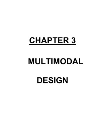
Cleaning Access Guidelines 12” below equipment 36” around equipmentWidthCleaningClearance8”1”24”4” 24”12”
Avoid small gaps
Substantially Flush GasketsSubstantially Flush (SF) 1/32" (0.794 mm) maximum
Gaskets and O-ring Removable or Bonded Groves not deeper then width unless removable Reference 3-A Charts for groove radii
Exposed Threads - Sanitary Acme Design
Coil Springs Round cross section No flat ends for CIP applications 1/32” minimum space betweencoils under compression 3/32”minimum space betweencoils in relaxed condition forspring with 1” outside diameteror less
Bearings and Shafts Bearings in product contact zone shall be nonlubricated or product lubricated. Bearings outside product zone need to be onstand-offs Shafts above product level shall be designed toprevent the entrance of contamination.
Shaft and Bearings -1”
Bearing Mounting Welded stand-off preferredAvoid sleeve stand-offsNon-corrosiveDo not mount over product
Oil filled gearbox mount outside product contactsurfaces
Opening and Covers Minimum 3/8 inch flange upward Umbrella Cover
Joints in NPCS Continuous Weld Bolted connection onwelded stand-offs Socket head boltmust be mountedhorizontal to drain No blind rivets
Installation and Maintenance Install in a hygienic condition Cleaning clearancesElectrical washdownCorrosion resistant materialsFree drainingNot over floor drains Maintain hygienic conditions
Questions ?
Hygienic Design Standards and Guidelines Larry Hanson. Key Cleanability Design Considerations Material of Constructions Surface Finishes Joint Design No Cracks or Crevices . Flat Gasket must be substantially flush Seal in Series with . Welded Joints Must continuously welded Must meet surface finish requirements stated