Transcription
OREGON OSHAYARDING AND LOADING HANDBOOK
OREGON OSHAYARDING AND LOADING HANDBOOKTABLE OF CONTENTSIntroductionSECTION 1. PLANNING AND SETUPSECTION 2. OPERATIONSChapter 1. Planning for the Unit 4Chapter 7. Yarding the Logs 82Think Safety FirstPre-work ChecklistLanding OperationsRigging CrewMajor Hazards for the Rigging CrewChapter 2. Setting Up the Landing 7Production PlanningYarding MachineryStandard LayoutsDevelop a Safe Work AreaChapter 8. Landing the Turn 109Landing CrewLanding the TurnUnhooking the TurnMajor Hazards for the Landing CrewChapter 3. Machine and EquipmentInspection 20Chapter 9. Loading the Logs 123MachinerySparCarriages and RiggingWire RopeLine ConnectionsMachine OperationsLog TrucksSECTION 3. SAFETY GUIDEChapter 10. Worker Safety Rules 129Chapter 4. Anchors 30Safety and Health ProgramSafety Planning and Hazard ControlPersonal Protective EquipmentBasic Tool SafetyControlling Fires in Forest OperationsFire Prevention for Chainsaw UseChainsaw SafetyFirst Aid for SurvivalAnchor SafetySingle-stump AnchorsMultiple-stump AnchorsCable Clips and SpikesAlternate AnchorsChapter 5. Setting Up the Yarder 43Moving in the YarderGuylinesRaising the SparChanging RoadsChapter 11. Signs and Signals 142Signal UseVoice SignalsWhistle SignalsTraffic SignsHand SignalsChapter 6. Rigging the Yarding Lines 60Yarding SystemsLine SafetyTailholdsElevated SupportsTree ClimbingYarding and Loading Glossary 1481
Oregon OSHA Yarding and Loading HandbookIntroductionT Oregon Occupational Safety and Health Standards,his handbook focuses on skyline yarding as themost common type of logging operation in Oregon,assuming steep terrain and use of a yarder tower andcable system. Basic information may also apply to otherlogging methods.Division 7 Forest Activities. 2008. Oregon OSHA. Cable Yarding Systems Handbook. 2006. WorkSafeBC. British Columbia, Canada. Practical Methodology for Operational Layout ofThe material in the handbook is intended to reinforcesafe practices in a hazardous work environment, basedon Oregon OSHA Division 7 Forest Activities safety andhealth standards, and generations of practical experiencein Oregon logging. The main intent is to provide loggerswith a readable, easy-to-use resource.Commercial Skyline Thinning Systems. 2004. OregonState University, Forest Research Laboratory. Best Practice Guidelines for Cable Logging. 2000.FITEC, New Zealand. Yarding and Loading Handbook. 1993. OregonOSHA.This handbook does not contain all forest activityrules and is not a substitute for Oregon OSHADivision 7 – which should be consulted for acomplete understanding of work safety rules. Designing Double-Tree Intermediate Supports forMultispan Skyline Logging. 1984. Oregon StateUniversity Extension Service. Cable Logging Systems. 1974. U.S. Forest Service,Technical information is provided in some instances forquick reference, but loggers should also consult morecomplete technical manuals for specific topics, suchas setting appropriate guyline zones or engineeringspecifications for alternative anchor systems. Alwaysconsult Division 7 work rules – which are continuallyreviewed and updated – and the manufacturer’s operatinginstructions for specific equipment.Pacific Northwest Region.Illustrations in the handbook typically show modelequipment and behavior. Negative examples are markedwith the symbol. Please observe the difference.Production of the Oregon OSHA Yarding and LoadingHandbook included the following contributions.Logging Safety Consultant: Jeff WimerTraining is critical before working in the woods. Gethands-on training with a competent logger beforeengaging in any yarding and loading activity. Thishandbook provides useful information, but does notreplace training in the field and supervised experience inthe safe use of tools, equipment, and procedures.Editor: Terry HammondIllustrator: Phil FehrenbacherTechnical Review: Mike Lulay, Oregon Forest ActivitiesCommittee, Oregon OSHALogging is a complex enterprise, and the challenge oforganizing a comprehensive view of yarding and loadinghas been greatly helped by 40 years of attention to bestpractices in other published resources. Publicationsfrom Oregon, British Columbia, and New Zealandwere consulted. Primary source materials included thefollowing:2
Section 1Planning and Setup3
Oregon OSHA Yarding and Loading HandbookCHAPTER 1PLANNING FOR THE UNITup to the logger. The best locations may not be clear untiltimber is on the ground. Assess the basic requirementsfor each potential landing, using the following criteria:THINK SAFETY FIRSTPlanning a unit for logging requires up-front attention towork safety requirements. Implement the firm’s generalsafety and health plan, and then assess specific workingconditions and hazards in the unit (see Chapter 10). Make sure the area to be logged is accessible andyarding distances are minimized. Ensure deflection is adequate. Assess each landing according to the availablemachinery; assure adequate landing size, feasiblelanding to tailhold distances, tailhold anchor, andpayload requirements. Determine if adequate guyline stumps or otheranchor types are available for each landing. Assess danger trees near the landing.PRE-WORK CHECKLIST IMPORTANT: Look at the worst yarding situationThe unit plan will help ensure a safe and productiveoperation. The following items should be checked offbefore setting loggers to work.from each landing and determine if the machineshave sufficient capacity for it.[4] Landing Size. Landowners or loggers will developthe working size of the landing according to productionand safety requirements, involving the volume of timber,terrain, decking, equipment, and logging method (seeChapter 2). An initial assessment of the unit for landinglocations should calculate the required minimum size forthe following basic features.[1] Hazard Assessment. Survey the setting for hazards,such as standing snags, rock outcroppings, streambuffers, or power lines. Pay attention to unique featuresof the unit. Topographical maps are useful. Determineways to avoid or eliminate identified hazards in the workareas. Machines – maintain at least 3 feet of space between[2] Weather. Consider how the weather may affect thecrew and roads. Snow, wind, and rain can create hazards.Pay particular attention to the roads and their ability tofunction in difficult weather.any machine. Landing edge – check the stability of the slope onthe side where work will be performed. In someinstances, it may be necessary to work over the edgeto get logs moved.IMPORTANT: Assess the ability of emergency personnelto reach the logging site in adverse weather conditions. Landing chute – accommodate at least two-thirds[3] Landing Locations. Identify the best landinglocations and potential secondary locations. Usually,landings are already determined or choices are limited bythe terrain. In some cases, the landing locations are leftthe length of the longest log landed. Decking area – must be adequate for the volume andsize of logs processed.4
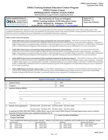
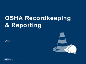
Chapter 1. Planning the UnitTRUCK TURNAROUNDFIRE TRUCKLOG TRUCK BACKED INCRUMMYGUYLINESLOG DECKCARRIAGE ON SKYLINELOADERLANDINGCHUTEYARDERTURNPROCESSORView of a typical landingSURGE AREA Surge area – reserve a place where the processor cansurfacing, overhead power lines, adverse grades, tightcurves, and so on.lay logs off to the side until there is time to catch upand move the logs to the decking area.[6] Timber Cutting. Determine the method of falling.Terrain will dictate whether the unit will be mechanicallyfelled or hand felled. The timber size, landing area,terrain, and machinery to be used will determine whethertree-length or log-length methods of timber cutting willbe used. These decisions will affect the size of the landingand associated hazards. Loading – where log trucks turn around, load, andexit.[5] Haul Roads. Position machinery and arrange thesequence of logging to minimize conflicts with haulroads. Movement of log trucks on the landing shouldnot interfere with the logging process. Consider howthe road connects to the landing and how it relates topotential decking areas. Also, anticipate the interactionbetween the haul road and the ongoing logging andfalling processes. It may be necessary to control accesswith flaggers at the landing or where lines cross the haulroad.Timber should be felled to lead to minimize risk to therigging crew that follows. If snags or other hazard treesare left for the rigging crew, the unsafe timber needs tobe clearly identified with hazard ribbon.IMPORTANT: Communicate with fallers to save supporttrees that may be needed in the skyline corridors. Also,inform operators of mechanical fellers to save anchorstumps around all potential landings. Mechanical fellerstypically cut timber close to the ground, which eliminatesthe possibility of using those stumps as anchors.Also consider the entire haul route. Look at the maincounty or state access roads and determine if thereare any obstacles to moving heavy machinery, such asweight-limited bridges, unstable roads, inadequate road5
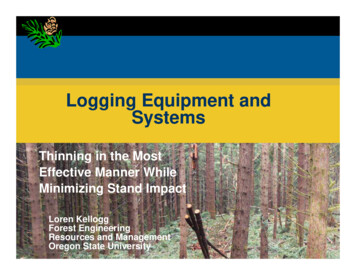
Oregon OSHA Yarding and Loading HandbookRemote locations may have problems with communicationdead spots, and may be difficult to access. If externalcommunication is not possible at a landing, find alocation nearby where communication works. Make sureeveryone involved with the logging process is aware ofpoints where external communication is possible.Acceptablestump height forguyline anchor[9] Internal Communications. During the operation,radios and signal devices are essential tools forcommunication. Determine in advance what machinesand equipment will be necessary for the particular unit.Typical stumpheight frommechanical feller Radios – make a test; radio systems, analog ordigital, can be prone to interference.[7] Anchor Requirements. For each potential landing,evaluate the available stump anchors and whetheradditional anchoring requirements will be needed.Other anchors include tieback or multiple stumpanchors, deadman anchors, equipment anchors, andtipping-plate earth anchors (see Chapter 4). Timbersize, logging distance, soil conditions, payload capacity,and machinery in use, all play a role in guyline anchorrequirements. Whistle system – a whistle system must beunderstood by all of the crew, and any modificationsin the whistle system must occur only after all of thecrew understands the changes. Horn – the horn must be loud enough to hear overthe entire unit. Prepare for situations where anauxiliary whistle will be needed on landing ledgesto communicate to the rigging crew.[8] External Communications. Communication withemergency services and plans for emergency evacuationare essential elements of the safety and health program.Evaluate communication links and establish emergencyplans for each proposed landing, including the followingpoints:IMPORTANT: Register whistle systems with OregonOSHA to ensure uninterrupted signals. By registeringa radio frequency, interference, overlap, fadeout, andblackout can be eliminated or greatly reduced. (Registerby contacting Oregon OSHA directly, or online at www.orosha.org under “Radio permits for forest activity.”) Make sure transportation is available to the nearestsuitable medical facility.[10] Pre-work Safety Meeting. In the rush to startlogging in a new unit, it is easy to forget to schedulea pre-work meeting with everyone on the loggingcrew. The importance of communication is too oftenunderestimated. Don’t start work without a pre-worksafety meeting. A pre‑work meeting provides anopportunity to share information and begin thinking asa team. Loggers with expertise in different aspects oflogging operations may be able to provide useful optionsand practical advice; and everyone together needs tobecome familiar with the particular hazards identified inthe setting and how they will be eliminated or controlled.Discuss emergency communications and response at themeeting. Identify a point where an ambulance or helicopterairlift can be met. Keep emergency contact information near theworksite communication device, including phonenumbers for land or air evacuation service, andimportant contacts. Write out land directions to the worksite. Identifythe location by township, range, and section; and bylatitude and longitude if air service is available. Consider using identifying markers on roads andintersections to assist emergency access, so firstresponders unfamiliar with the area can quickly findthe correct route.6
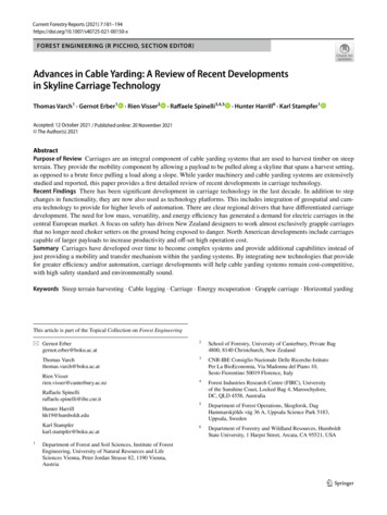
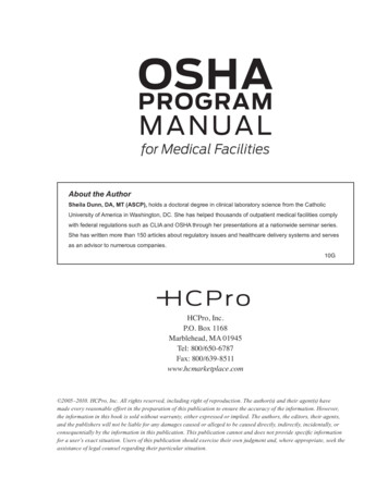
Chapter 2. Setting Up the LandingCHAPTER 2SETTING UP THE LANDINGPRODUCTION PLANNINGPROPER DEFLECTION IN SKYLINEPROPER DEFLECTION IN SKYLINEEach landing will present unique features in terrain,layout, and productivity. In a highly productiveoperation a lot of wood will go through the landing.An efficient layout that minimizes interferencebetween machine operation and people on the groundincreases both production and safety. Keepingthe work flowing smoothly reduces the risk of anunexpected incident and possible injury. For bestresults, consider the following conditions beforemoving in to set up a landing.AOn a constant slope, anchor theskyline to an opposite hillside toprovide deflection.BA concave slope providesideal ground conditions for aYarding system. Determine the yarding system touse, considering the available equipment, terrain,timber size, and yarding distances (see Chapter 6).single-span skyline.Size of timber and number of sorts. Tree-lengthlogging requires much more room than log-length. Isthere room to safely deck larger sorts of logs? Be surethere is a sufficient landing-chute area to safely land thelogs.is necessary. Communicate clearly in the planning stage,so everyone understands work procedures and hazards.IMPORTANT: On small landings, plan in advance forsituations where the loader operator may need to grabthe logs to effectively land a turn, and hold them whilethe chaser unbells and hands them off to the processor.Prepare for runaway logs on steep terrain and keep therigging crew well in the clear.Volume of timber. In highly productive sites, it may benecessary to include a surge area on the landing. Thiswill allow the processor to deck unprocessed logs untilincoming volume slows. Be sure there is adequate roomto deck the volume of timber and expected log sorts.Deflection. Deflection is critical in logging with cablesystems. Poor deflection will affect payload capacityand reduce production, and in some cases – as in goingover a blind ridge to log behind that ridge – may makeit impossible to tighten the lines enough to effectivelyget the logs off the ground. Many loggers can assessthe terrain by eye. In uncertain situations, running adeflection line prior to rigging up allows a closer lookat the terrain and a clear indication of how tight the linesmay have to run. At this stage, the landings are already inplace, and the logger will need to assess what deflectionis available and choose an appropriate yarding system.Slope of surrounding terrain. The slope of surroundingterrain dictates how logs will be landed, how many logs,and where they may be decked. On steep terrain, theremay be a problem landing tree‑length logs. Very steepterrain may make it impossible to increase the size oflanding and decking areas, and requires machinesand landing personnel to work in close proximity. Inthat case, the organization of the landing needs to beextremely efficient with space, and work processes needto be tightly organized to avoid interference betweenmachines and people on the ground. Increased diligence7
Oregon OSHA Yarding and Loading HandbookRunning Deflection LinesRunning deflection lines involves use of clinometers and tapeto show the profile of the terrain in a logging road. Two personswith clinometers stand at either end of a terrain break, with thetape running between them to establish the length and pitch ofeach break. Start at the back end of the landing and work downthe logging corridor to just beyond the tailhold. The data can be analyzed by the “chain and board”method, or entered into a computer program like LoggerPC or SkylineXL (both programs areavailable from USFS or OSU). It may be possible to obtain this information from a topography map,government agency, or timber seller.Deflection Lines and HaulbacksRunning deflection lines helps assess payload, lift, and the possible need for haulback use duringyarding.Payload AnalysisThe payload analysis screen shown here from thecomputer program SkylineXL works on input forequipment and terrain to estimate an appropriatepayload. Using a computer program is the easiestway to calculate payload. Adjust the estimate byadditional variables related to the particular situationfor environment, equipment, and human factors.8
Chapter 2. Setting Up the LandingYARDING MachineryPayload analysis. There are several ways to analyzethe payload for any given tower, landing, and terraincombination. Analyze the worst payload scenario foreach landing to determine how much wood can be safelycarried on the skyline. If suitable payload is not availablewith a tailhold down low on a unit, consider finding atailhold up the back side, or use a tailtree to raise the lineand give more deflection.In most cases, loggers will come to a job with a set ofmachinery on hand. After evaluating the conditions at thelanding as outlined above, the capacity of the availableequipment needs to be reassessed to determine if it meetsthe task. Principal options and features are outlinedbelow for yarders, log loaders, and processors.YardersGuyline anchors. Locate and mark available guylinestumps suitable for the expected yarder locations. Ifappropriate stumps are not available, then other anchoringmethods – such as deadman or equipment anchors – needto be established before rigging up the tower.Yarders of various types have been around for more thana century. Early yarders were ground-based and relied onlarge rigging to move the turn of logs. Later, trees wererigged to lift the lines and allow the logs to clear mostobstacles. Mobile steel towers were introduced in the past60 years. Older mobile towers are still working, and newtowers keep appearing. Always check the manufacturer’smanual for essential features and inspection points oneach particular machine.IMPORTANT: Communicate with the falling crew to besure potential guyline stumps are not cut off too shortat any potential landing sites. Some landing locationsmay not be identified beforehand, because the terraincan be seen much better once timber is on the ground.A different landing and set of anchors may prove morefavorable. Also, plan ahead to preserve necessary tailand support trees.Order of the skyline roads to yard. Normally, skylineroads work away from the side where the logging roadenters the landing and the position of the log loader.Working away allows the log loader more room as thevolume of logs accumulates. However, if the terraincreates a sidehill for the rigging crew, it is more importantto log the felled timber from top to bottom for the safetyof the crew. Then, the skyline roads might start fartheraway and move toward the loader. Plan road changesin advance. Also, consider obstacles that may obstructmoving the skyline.9
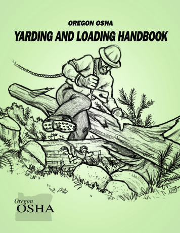
Oregon OSHA Yarding and Loading HandbookStraight tube telescoping tower. Uses a hydraulicram or multiple-sheave cable system to raise thetower. Some telescoping towers allow use at thetelescoped height or partially retracted, which canbe an advantage if guyline anchors need to beplaced closer to the landing or on steep slopes.Fixed leaning tower. A one-piece tower can befront‑mounted vertical, or leaning. The height of thetower varies with make and model.Travel: Self-propelled / Trailer mount / Track mountLong reach; Height 90-110 feetTravel: Self-propelled / Trailer mount / Track mountAdvantages Heavy payloadsMedium reach; Height 40-80 feet Tower height allows for more line deflectionAdvantages Faster line setup Some yarders allow yarding 180 degrees Smaller landing requirementswithout moving yarder or guylines Lighter – easier to moveDisadvantages Heavy and hard to move; requires better roads; Lower guyline anchor requirementsmay have to be disassembled to move on publicroadsDisadvantages Yarding window smaller – need to move tower Large landing requirementsand guylines more often Need large guyline anchor capacity Smaller payloads than straight tube towers.10
Chapter 2. Setting Up the LandingSwing yarder. Similar to the fixed leaning tower innearly all respects. The swing yarder is also capableof swinging logs onto the road or landing. Capableof using a running skyline. Track mounts are morestable when moving.Grapple yarder. Uses a swing yarder or yoadersystem. The grapple is controlled by signals fromthe rigging slinger, or by the yarder engineer usinga video link on the carriage. Swing capability isnecessary to allow a wider logging corridor. Agrapple system is typically used in conjunction witha machine anchor and elevated support on the backend of the unit, making for quick road changes.Yoader. This yarder is typically a log loader withtwo drums mounted at the base of the boom. Bothlines run through sheaves mounted on the boomor heel rack. The lines can be set up in a standing,live, or running skyline configuration, or a high‑leadconfiguration.Travel: Track mount / Rubber-tire mountTravel: Track mount / Rubber-tire mountMedium to short reachMedium reachAdvantagesAdvantages No guylines required Smaller crew size, typically a yarder engineer,landing worker, and a hooktender Easy to move Easy road changes Easy road changes Easy rig up – ideal for smaller logging areas Easy rig up – ideal for smaller logging areasDisadvantages Can be used as a loader Requires extensive planning to achieve fullDisadvantagesproduction Slower line speeds Must have moderate to good deflection Stability can be an issue – blocking up front of Generally need access to back of unittrack helps (See Chapter 5) Limited yarding width Rigging height is limited11
Oregon OSHA Yarding and Loading HandbookTong-tosserwith grappleStiff-leg spar yarder. One of various configurationsfor this yarder uses an excavator or log loader fittedwith a third boom between the main and jib boom,which is elevated to provide lift. The elevated boomis typically rigged with two or three lines. Workswith high lead, standing, running, or slacklineconfigurations.Jammer system with chokersTravel: Track mountTong-tosser/Jammer system. These two systemsuse basically the same machine as the yoader, witheither tongs or chokers on the end of the line tosecure the logs. This version typically uses onedrum on the machine with a spitter wheel at the endof the boom to pull the line from the drum and pushit out to the brush. The yarder engineer usually getsthe tongs or chokers swinging and then tosses themto the waiting choker setters.Medium reachAdvantages May not need guylines Easy to move Easy road changes Easy rig up – ideal for smaller logging areas Can be used as a loader or excavatorTravel: Track mountShort reach Jib boom offers great stabilityAdvantages Rigging height is greater than yoader or Same as yoader Does not require line layouts or anchorstong‑tosser/jammer systemDisadvantages Slower line speedsDisadvantages Same as yoader. Greater potential risk to Attached tower boom may need to be removedrigging crew.for other operations Heavy stress on boom and components12
Chapter 2. Setting Up the LandingLog LoadersThe earliest way to move logsin Oregon followed ancientmethods of heeling, rolling,and floating. Mechanizedloading began with cablesystems. Presently, hydraulicexcavators with a log-loadingboom load the majority oflogs.Rubber-tire mount. Not as mobile astrack‑mounted loaders.Advantages Can be driven long distances – greatfor roadside cleanup over large areasDisadvantages Not as mobile in short moves Requires outriggers for stabilityTrack mount. Track-mounted loaders allow for easymovement in and around a landing area. They are slow tomove over long distances, usually loaded on a lowboy formovement between jobs. On terrain where they can operatesafely, some track-mounted loaders are capable of loggingsmall areas around the landing or an entire unit.Advantages Most common Easy mobility Can be used for shovel logging Can be set up for quick change to excavator or processorDisadvantages Transport required if moved long distances13
Oregon OSHA Yarding and Loading HandbookLog ProcessorsWhole-tree processors have been around Oregonsince the mid-1970s as logging operationsstarted working more in smaller timber, andmore wood needed to flow through the landingto stay economical. The introduction of logprocessors allowed higher production rates,but also created new hazards in operating andworking around the additional machinery.Dangle head. Mounted onto a standard log-loadingboom. Uses feed wheels to pull the stem throughthe processor.Advantages Smaller turn radius Can process logs not lying in lead to machineDisadvantages Feed rolls – some mills won’t allow damagecaused by some styles of feed rolls Requires butt of tree to be cut off to give zeroreferenceStroke boom. Stroke boom delimbers were amongthe first whole-tree processors. The delimber canscan the entire tree stem for bucking decisions. Longbooms can be a hindrance on small landings.Advantages No feed wheels help reduce damage to stemDisadvantagesGround-based processor. Pulls the stem throughdelimbing knives on top of the machine. Some havea saw for cutting stems to length. Long boom, requires larger turn radius; need towatch behind to not strike other machines Transport: height on lowboy can be an issueAdvantages Requires trees to be in lead with machine Low initial cost Lower maintenance Suitable for smaller landingsDisadvantages Does not measure log length14
Chapter 2. Setting Up the LandingSTANDARD LAYOUTSOperational zones. Each machine and vehicle at thelanding site has a zone of normal operation. A minimum3-foot clearance needs to be maintained between allpieces of equipment.Machine selection changes the way operations areorganized, but a few critical factors apply to any landing.First, look at the landing again after the timber is on theground to be sure what is needed. The original plan couldchange. Consider the following elements:IMPORTANT: Pay attention where zones of operationintersect, and to potential impacts between machines,vehicles, and workers on the ground. Use barricades,danger ribbon, or other effective control measures tolimit conflicts and worker access.Landing size. The size of the landing is determinedby conditions and machinery choices identified in theplanning stage. The logging crew will need to decidehow to best use the landing as planned. Confirm that thelanding is large and level enough for safe movement, somachines or swinging logs will not strike standing timber,rigging, or other machines or objects. Also consider thesurrounding ledges. Make sure logs can be landed anddecked without risk of the logs or other materials slidingover the edge toward workers below. A landing that istoo small can create safety hazards and delay productionas machines, trucks, and logs compete for space.Downhill yarding. Downhill yarding requires a runoutarea to prevent material that may come down the hillsidefrom striking the yarding equipment.Surge area. When trees are felled and bucked, the logloader can take logs directly from the landing chuteand place them in log decks for transportation. With theuse of a processor, an intermediate surge area is oftennecessary, where logs are placed prior to processing.Split landings. Split or jump-up landings may benecessary on steeper ground where one level area isnot large enough to hold all of the machines, or wouldcreate greater risk to workers. Placing the yarder abovegives the yarder engineer a better view of everything, butcommunication can be affected, because hand signalswill be harder to use.IMPORTANT: Be sure the surge area is large enoughthat it will not be overloaded or create a hazard to therigging crew below from rolling or shifting logs.Log decks. A landing will commonly have multiple logdecks, sorted for various destinations. With most logsorts, there are some that accumulate faster than others,and those should typically be closer to the landingoperation. Consider the volume of wood that eachsort will create when planning the decking area. Somelanding areas may be so small that decking areas needto be created. Using tall stumps adjacent to the landingis one solution.Landing chute. The yarder needs to be set back far enoughfrom the front edge of the landing to allow logs to landsafely. The landing chute should be at least two‑thirdsthe length of the logs. Considerable hazards result whena log starts to run back downhill and the loader operatorhas to grapple the log to unbell the chokers. If logs needto be decked on the landing, make sure they will not slideor roll onto the crew below.Operational areas for the loader and log trucks. Setup the loading at the entrance to the landing, with the logdecks on either side where the trucks back up to the logloader. On landings where a processor is working, theloading is separated, but not a great distance from thelanding operation. The loader moves the logs betweenthe yarder or processor to the log decks.IMPORTANT: With tree-length logging, make surelonger trees can be safely landed, so they will not slideover the hill and strike the rigging crew. Logs for polepiling or an infrequent long break may be yarded, but thelog must be secured before unhooking the choker.15
Oregon OSHA Yarding and Loading HandbookOn smaller landings, establish procedures or control measures to avoid impacts whereverzones of machine operation intersect.Debris area. As logging proceeds, debris accumulates inthe landing area. If the debris needs to be placed over theed
Multispan Skyline Logging. 1984. Oregon State University Extension Service. Cable Logging Systems. 1974. U.S. Forest Service, Pacific Northwest Region. Illustrations in the handbook typically show model . equipment and behavior. Negative examples are marked with the symbol . Please observe the difference. Production of the Oregon OSHA