Transcription
Contrail NetworkingContrail Networking Service ProviderFocused Features GuidePublished2022-05-17Release2011
iiJuniper Networks, Inc.1133 Innovation WaySunnyvale, California 94089USA408-745-2000www.juniper.netJuniper Networks, the Juniper Networks logo, Juniper, and Junos are registered trademarks of Juniper Networks, Inc. inthe United States and other countries. All other trademarks, service marks, registered marks, or registered service marksare the property of their respective owners.Juniper Networks assumes no responsibility for any inaccuracies in this document. Juniper Networks reserves the rightto change, modify, transfer, or otherwise revise this publication without notice. Contrail Networking Contrail Networking Service Provider Focused Features Guide2011Copyright 2022 Juniper Networks, Inc. All rights reserved.The information in this document is current as of the date on the title page.YEAR 2000 NOTICEJuniper Networks hardware and software products are Year 2000 compliant. Junos OS has no known time-relatedlimitations through the year 2038. However, the NTP application is known to have some difficulty in the year 2036.END USER LICENSE AGREEMENTThe Juniper Networks product that is the subject of this technical documentation consists of (or is intended for use with)Juniper Networks software. Use of such software is subject to the terms and conditions of the End User License Agreement(“EULA”) posted at https://support.juniper.net/support/eula/. By downloading, installing or using such software, youagree to the terms and conditions of that EULA.
iiiTable of ContentsAbout the Documentation viiDocumentation and Release Notes viiiDocumentation Conventions viiiDocumentation Feedback xRequesting Technical Support xiSelf-Help Online Tools and Resources xiCreating a Service Request with JTAC xii1Data Plane OptimizationConfiguring the Data Plane Development Kit (DPDK) Integrated with ContrailvRouter 14DPDK Support in Contrail 14Preparing the Environment File for Provisioning a Cluster Node with DPDK 14Creating a Flavor for DPDK 16Configuring and Verifying MTU for DPDK vRouter 17Configuring Single Root I/O Virtualization (SR-IOV) 18Overview: Configuring SR-IOV 19Enabling ASPM in BIOS 19Configuring SR-IOV Using the Ansible Deployer 19Configuring SR-IOV Using Helm 21Launching SR-IOV Virtual Machines 23Using the Contrail Web UI to Enable and Launch an SR-IOV Virtual Machine 24Using the CLI to Enable and Launch SR-IOV Virtual Machines 25Optimizing DPDK vRouter Performance Through Full CPU Partitioning and Isolation 26Contrail DPDK vRouter Support for Intel DDP Technology in Fortville NICs 28Contrail vRouter MAC Address - IP Address Learning and Bidirectional Forwarding andDetection Health Checking for Pods on Virtual Machines 30
iv2Advanced Network TopologiesConfiguring Virtual Networks for Hub-and-Spoke Topology 34Route Targets for Virtual Networks in Hub-and-Spoke Topology 34Example: Hub-and-Spoke Topology 35Troubleshooting Hub-and-Spoke Topology 36Remote Compute 40Remote Compute Overview 41Remote Compute Features 41Remote Compute Operations 41Subcluster Properties 42Inter Subcluster Route Filtering 42Provisioning a Remote Compute Cluster 433Advanced Service Chain ConfigurationCustomized Hash Field Selection for ECMP Load Balancing 52Overview: Custom Hash Feature 52Using ECMP Hash Fields Selection 54Configuring ECMP Hash Fields Over Service Chains 54Routing Policy 55Applying Routing Policy 57Match Condition: From 57Routing Policy Action and Update Action 58Applying Routing Policies to Secondary Routes 59Routing Policy Configuration 59Configuring and Troubleshooting Routing Policy 60Create Routing Policy 61Configure Service Instance 62Configure the Network Policy for the Service Chain 62Using a VNC Script to Create Routing Policy 62Verify Routing Policy in API Server 64Verify Routing Policy in the Control Node 65Verify Routing Policy Configuration in the Control Node 65Verify Routing Policy Configuration on the Routing Instance 66
vControl for Route Reorigination 66Configuring and Troubleshooting Reorigination Control 68Creating a Routing Policy With Extended Communities in Contrail Command 70Creating Routing Policies for QFX Series Devices in Contrail Networking 75Service Instance Health Checks 80Health Check Object 81Health Check Overview 81Health Check Object Configuration 81Creating a Health Check with the Contrail Web UI 83Using the Health Check 84Health Check Process 84Bidirectional Forwarding and Detection Health Check over Virtual Machine Interfaces 85Bidirectional Forwarding and Detection Health Check for BGPaaS 85Health Check of Transparent Service Chain 86Service Instance Fate Sharing 86ECMP Support in Service Chain 87Service Chain with Equal-Cost Multipath in Active-Active Mode 87Service Chain with Health Check 88Route Reflector Support in Contrail Control Node 88Benefits of RRs in Contrail 89Configuring Route Reflectors from Contrail Command 90BGP as a Service 93Understanding BGP as a Service 93Contrail BGPaaS Features 93BGPaaS Use Cases 95Configuring BGPaaS using VNC API 96Configuring BGPaaS from Contrail Web UI 97Configuring BGPaaS from Contrail Command 99
viFat Flows 101Understanding Fat Flow 101Configuring Fat Flow from Contrail Command 102Limitations of Fat Flow 114Use Case: Configuring Fat Flows from Contrail Command 114Overview 115Ignore Address - Source, Destination 115Ignore Address - None 116Prerequisites 117Getting Started 118Configuration 119Create Virtual Network 120Create Virtual Machine 121Create Service Template 123Add Service Instance 125Configure Fat Flow 127Create Service Policy 129Attach Service Policy 130Launch Virtual Machine 130Understanding Flow Sampling 132Flow Sampling 133Flow Handling 134Flow Aging 134TCP State-Based Flow Handling and Aging 135TCP State-Based Flow Handling 135Protocol-Based Flow Aging 135
viiAbout the DocumentationIN THIS SECTIONDocumentation and Release Notes viiiDocumentation Conventions viiiDocumentation Feedback xRequesting Technical Support xiUse this guide to understand the features that would be used by service providers. This guide also providesinformation about advanced service chain configuration in Contrail Networking.Contrail Networking product documentation is organized into multiple guides as shown inTable 1 on page vii, according to the task you want to perform or the deployment scenario.Table 1: Contrail Networking GuidesGuide NameDescriptionContrail Networking InstallationProvides step-by-step instructions to install and bring up Contrail and its variousand Upgrade Guidecomponents.Contrail Networking forProvides information about installing and using Contrail Networking in containerizedContainer Networkingenvironments using Kubernetes orchestration.Environments User GuideContrail Networking FabricProvides information about Contrail underlay management and data centerLifecycle Management Guideautomation.Contrail Networking and SecurityProvides information about creating and orchestrating highly secure virtualUser Guidenetworks.Contrail Networking ServiceProvides information about the features that are used by service providers.Provider Focused Features GuideContrail Networking Monitoringand Troubleshooting GuideProvides information about Contrail Insights and Contrail analytics.
viiiDocumentation and Release Notes To obtain the most current version of all Juniper Networks technical documentation, see the productdocumentation page on the Juniper Networks website at https://www.juniper.net/documentation/.If the information in the latest release notes differs from the information in the documentation, follow theproduct Release Notes.Juniper Networks Books publishes books by Juniper Networks engineers and subject matter experts.These books go beyond the technical documentation to explore the nuances of network architecture,deployment, and administration. The current list can be viewed at https://www.juniper.net/books.Documentation ConventionsTable 2 on page viii defines notice icons used in this guide.Table 2: Notice IconsIconMeaningDescriptionInformational noteIndicates important features or instructions.CautionIndicates a situation that might result in loss of data or hardwaredamage.WarningAlerts you to the risk of personal injury or death.Laser warningAlerts you to the risk of personal injury from a laser.TipIndicates helpful information.Best practiceAlerts you to a recommended use or implementation.Table 3 on page ix defines the text and syntax conventions used in this guide.
ixTable 3: Text and Syntax ConventionsConventionDescriptionExamplesBold text like thisRepresents text that you type.To enter configuration mode, typethe configure command:user@host configureFixed-width text like thisRepresents output that appears onthe terminal screen.Italic text like this Introduces or emphasizes importantnew terms. Identifies guide names. Identifies RFC and Internet drafttitles.user@host show chassis alarmsNo alarms currently active A policy term is a named structurethat defines match conditions andactions. Junos OS CLI User Guide RFC 1997, BGP CommunitiesAttributeItalic text like thisRepresents variables (options forConfigure the machine’s domainwhich you substitute a value) inname:commands or configurationstatements.[edit]root@# set system domain-namedomain-nameText like thisRepresents names of configuration To configure a stub area, includestatements, commands, files, andthe stub statement at the [editdirectories; configuration hierarchyprotocols ospf area area-id]levels; or labels on routing platformhierarchy level.components. The console port is labeledCONSOLE. (angle brackets)Encloses optional keywords orstub default-metric metric ;variables. (pipe symbol)Indicates a choice between themutually exclusive keywords orvariables on either side of the symbol.broadcast multicast(string1 string2 string3)The set of choices is often enclosedin parentheses for clarity.# (pound sign)Indicates a comment specified on thersvp { # Required for dynamic MPLSsame line as the configurationonlystatement to which it applies.
xTable 3: Text and Syntax Conventions (continued)ConventionDescriptionExamples[ ] (square brackets)Encloses a variable for which you cancommunity name members [substitute one or more values.community-ids ]Indention and braces ( { } )Identifies a level in the configuration[edit]hierarchy.routing-options {static {; (semicolon)route default {Identifies a leaf statement at anexthop address;configuration hierarchy level.retain;}}}GUI ConventionsBold text like thisRepresents graphical user interface(GUI) items you click or select. In the Logical Interfaces box, selectAll Interfaces. To cancel the configuration, clickCancel. (bold right angle bracket)Separates levels in a hierarchy ofIn the configuration editor hierarchy,menu selections.select Protocols Ospf.Documentation FeedbackWe encourage you to provide feedback so that we can improve our documentation. You can use eitherof the following methods: Online feedback system—Click TechLibrary Feedback, on the lower right of any page on the JuniperNetworks TechLibrary site, and do one of the following:
xi Click the thumbs-up icon if the information on the page was helpful to you. Click the thumbs-down icon if the information on the page was not helpful to you or if you havesuggestions for improvement, and use the pop-up form to provide feedback. E-mail—Send your comments to techpubs-comments@juniper.net. Include the document or topic name,URL or page number, and software version (if applicable).Requesting Technical SupportTechnical product support is available through the Juniper Networks Technical Assistance Center (JTAC).If you are a customer with an active Juniper Care or Partner Support Services support contract, or arecovered under warranty, and need post-sales technical support, you can access our tools and resourcesonline or open a case with JTAC. JTAC policies—For a complete understanding of our JTAC procedures and policies, review the JTAC UserGuide located at uides/7100059-en.pdf. Product warranties—For product warranty information, visit https://www.juniper.net/support/warranty/. JTAC hours of operation—The JTAC centers have resources available 24 hours a day, 7 days a week,365 days a year.Self-Help Online Tools and ResourcesFor quick and easy problem resolution, Juniper Networks has designed an online self-service portal calledthe Customer Support Center (CSC) that provides you with the following features: Find CSC offerings: https://www.juniper.net/customers/support/ Search for known bugs: https://prsearch.juniper.net/ Find product documentation: https://www.juniper.net/documentation/ Find solutions and answer questions using our Knowledge Base: https://kb.juniper.net/ Download the latest versions of software and review release re/ Search technical bulletins for relevant hardware and software notifications:https://kb.juniper.net/InfoCenter/ Join and participate in the Juniper Networks Community Forum:https://www.juniper.net/company/communities/ Create a service request online: https://myjuniper.juniper.net
xiiTo verify service entitlement by product serial number, use our Serial Number Entitlement (SNE) mentsearch/Creating a Service Request with JTACYou can create a service request with JTAC on the Web or by telephone. Visit https://myjuniper.juniper.net. Call 1-888-314-JTAC (1-888-314-5822 toll-free in the USA, Canada, and Mexico).For international or direct-dial options in countries without toll-free numbers, support/.
1CHAPTERData Plane OptimizationConfiguring the Data Plane Development Kit (DPDK) Integrated with ContrailvRouter 14Configuring Single Root I/O Virtualization (SR-IOV) 18Optimizing DPDK vRouter Performance Through Full CPU Partitioning andIsolation 26Contrail DPDK vRouter Support for Intel DDP Technology in Fortville NICs 28Contrail vRouter MAC Address - IP Address Learning and Bidirectional Forwardingand Detection Health Checking for Pods on Virtual Machines 30
14Configuring the Data Plane Development Kit (DPDK)Integrated with Contrail vRouterIN THIS SECTIONDPDK Support in Contrail 14Preparing the Environment File for Provisioning a Cluster Node with DPDK 14Creating a Flavor for DPDK 16Configuring and Verifying MTU for DPDK vRouter 17DPDK Support in ContrailContrail Networking supports the Data Plane Development Kit (DPDK). DPDK is an open source set oflibraries and drivers for fast packet processing. DPDK enables fast packet processing by allowing networkinterface cards (NICs) to send direct memory access (DMA) packets directly into an application’s addressspace, allowing the application to poll for packets, and thereby avoiding the overhead of interrupts fromthe NIC.Integrating with DPDK allows a Contrail vRouter to process more packets per second than is possiblewhen running as a kernel module.In Contrail Networking, before you use DPDK the DPDK configuration should be defined in instances.yamlfor ansible based provision, or in host.yaml for helm-based provision. The AGENT MODE configurationspecifies whether the hypervisor is provisioned in the DPDK mode of operation.When a Contrail compute node is provisioned with DPDK, the corresponding yaml file specifies the numberof CPU cores to use for forwarding packets, the number of huge pages to allocate for DPDK, and the UIOdriver to use for DPDK.Preparing the Environment File for Provisioning a Cluster Node with DPDKThe environment file is used at provisioning to specify all of the options necessary for the installation ofa Contrail cluster, including whether any node should be configured to use DPDK.
15Each node to be configured with the DPDK vRouter must be listed in the provisioning file with a dictionaryentry, along with the percentage of memory for DPDK huge pages and the CPUs to be used.The following are descriptions of the required entries for the server configuration. : HUGE PAGES—Specify the percentage of host memory to be reserved for the DPDK huge pages. Thereserved memory will be used by the vRouter and the Quick Emulator (QEMU) for allocating memoryresources for the virtual machines (VMs) spawned on that host.NOTE: The percentage allocated to HUGE PAGES should not be too high, because the hostLinux kernel also requires memory. CPU CORE MASK—Specify a CPU affinity mask with which vRouter will run. vRouter will use only theCPUs specified for its threads of execution. These CPU cores will be constantly polling for packets, andthey will be displayed as 100% busy in the output of “top”.The supported format is hexadecimal (for example, 0xf). DPDK UIO DRIVER—Specify the UIO driver to be used with DPDK.The supported values include: vfio-pci—Specify that the vfio module in the Linux kernel should be used instead of uio. The vfiomodule protects memory access using the IOMMU when a SR-IOV virtual function is used as thephysical interface of vrouter. uio pci generic—Specify that the UIO driver built into the Linux kernel should be used. This optiondoes not support the use of SR-IOV VFs. This is the default option if DPDK UIO DRIVER is notspecified. mlnx – For Mellanox ConnectX-4 and Mellanox ConnectX-5 NICs.NOTE: For RHEL and Intel x710 Fortville-based NIC, use vfio-pci instead of the defaultuio pci generic.Use the standard Ansible or helm-based provision procedure. Upon completion, your cluster, with specifiednodes using the DPDK vRouter implementation, is ready to use.Sample configuration in instances.yml for ansible-based provisionBms1:provider: bmsip: ip-addressroles:
16vrouter:AGENT MODE: dpdkCPU CORE MASK: “0xff”DPDK UIO DRIVER: uio pci genericHUGE PAGES: 32000Sample configuration in host.yml for helm-based provision.AGENT MODE: dpdkCPU CORE MASK: “0xff”DPDK UIO DRIVER: uio pci genericHUGE PAGES: 32000Creating a Flavor for DPDKTo launch a VM in a DPDK-enabled vRouter hypervisor, the flavor for the VM should be set to use hugepages. The use of huge pages is a requirement for using a DPDK vRouter.Use the following command to add the flavor, where m1.large is the name of the flavor. When a VM iscreated using this flavor, OpenStack ensures that the VM will only be spawned on a compute node thathas huge pages enabled.# openstack flavor set m1.large --property hw:mem page size largeHuge pages are enabled for compute nodes where vRouter is provisioned with DPDK.If a VM is spawned with a flavor that does not have huge pages enabled, the VM should not be createdon a compute node on which vRouter is provisioned with DPDK.You can use OpenStack availability zones or host aggregates to exclude the hosts where vRouter isprovisioned with DPDK.NOTE: Note: By default, 2MB huge pages are provisioned. If 1GB huge page is required, it mustbe done by the Administrator.
17Configuring and Verifying MTU for DPDK vRouterThis section describes how you configure the maximum transmission unit (MTU) for DPDK vRouter. Toset MTU, you need to specify the desired value for mtu in the contrail vrouter dpdk bond.yaml file.network config:type: contrail vrouter dpdkname: vhost0members:type: interfacename: em3type: interfacename: em1mtu: 9100bond mode: 2bond policy: 802.3adYou can verify the configured value from hypervisor by running the following command: ip link list vhost039: vhost0: BROADCAST,MULTICAST,UP,LOWER UP mtu 9100 qdisc pfifo fast stateUNKNOWN mode DEFAULT group default qlen 1000link/ether 98:03:9b:a7:3b:a0 brd ff:ff:ff:ff:ff:ffYou can use the vif -g or vif --get command to view the status of the bond interfaces in a DPDK vRouter.For example,# vif --get 0Vrouter Interface Table[.]vif0/0PCI: 0000:00:00.0 (Speed 20000, Duplex 1) NH: 4Type:Physical HWaddr:00:1b:21:bb:f9:48 IPaddr:0.0.0.0Vrf:0 Mcast Vrf:65535 Flags:TcL3L2VpEr QOS:-1 Ref:26RX device packets:668852RX portbytes:110173140 errors:0packets:207344 errors:0
18RX queue errors to lcore 0 0 0 0 0 0 0 0 0 0 0 0 0 0 0 0 0 0Fabric Interface: eth bond bond0Status: UPDriver: net bondingSlave Interface(o): 0000:02:00.0Status: UPDriver: net ixgbeSlave Interface(1): 0000:02:00.1Status: UPDriver: net ixgbeVlan Id: 101VLAN fwd Interface: bondRX packets:207344bytes:45239337 errors:0TX packets:326159bytes:237905360 errors:4Drops:0TX portpackets:326145 errors:10TX device packets:915402bytes:511551768 errors:0See vRouter Command Line Utilities for a list of vRouter command line utilities.RELATED DOCUMENTATIONConfiguring Single Root I/O Virtualization (SR-IOV) 18Monitoring Bond Interfaces in DPDK Enabled DevicesvRouter Command Line UtilitiesDPDK official page: http://www.dpdk.orgConfiguring Single Root I/O Virtualization (SR-IOV)IN THIS SECTIONOverview: Configuring SR-IOV 19Enabling ASPM in BIOS 19Configuring SR-IOV Using the Ansible Deployer 19Configuring SR-IOV Using Helm 21Launching SR-IOV Virtual Machines 23
19Overview: Configuring SR-IOVContrail Networking supports single root I/O virtualization (SR-IOV) on Ubuntu systems and on Red HatEnterprise Linux (RHEL) operating systems as well.SR-IOV is an interface extension of the PCI Express (PCIe) specification. SR-IOV allows a device, such asa network adapter to have separate access to its resources among various hardware functions.As an example, the Data Plane Development Kit (DPDK) library has drivers that run in user space forseveral network interface cards (NICs). However, if the application runs inside a virtual machine (VM), itdoes not see the physical NIC unless SR-IOV is enabled on the NIC.This topic shows how to configure SR-IOV with your Contrail Networking system.Enabling ASPM in BIOSTo use SR-IOV, it must have Active State Power Management (ASPM) enabled for PCI Express (PCIe)devices. Enable ASPM in the system BIOS.NOTE: The BIOS of your system might need to be upgraded to a version that can enable ASPM.Configuring SR-IOV Using the Ansible DeployerYou must perform the following tasks to enable SR-IOV on a system.1. Enable the Intel Input/Ouput Memory Management Unit (IOMMU) on Linux.2. Enable the required number of Virtual Functions (VFs) on the selected NIC.3. Configure the names of the physical networks whose VMs can interface with the VFs.4. Reboot Nova compute.service nova-compute restart5. Configure a Nova Scheduler filter based on the new PCI configuration, as in the following example:
20/etc/nova/nova.conf[default]scheduler default filters PciPassthroughFilterscheduler available filters nova.scheduler.filters.all filtersscheduler available filters nova.scheduler.filters.pci passthrough filter.PciPassthroughFilter6. Restart Nova Scheduler.service nova-scheduler restartThe above tasks are handled by the Ansible Deployer playbook. The cluster members and its configurationparameters are specified in the instances.yaml file located in the config directory within the ansible-deployerrepository.The compute instances that are going to be in SR-IOV mode should have an SR-IOV configuration. Theinstance.yaml snippet below shows a sample instance definition.instances:bms1:provider: bmsip: ip-addressroles:openstack:bms2:provider: bmsip:ip-addressroles:config database:config:control:analytics database:analytics:webui:bms3:provider: bmsip: ip-addressroles:openstack compute:vrouter:SRIOV: trueSRIOV VF: 3
21SRIOV PHYSICAL INTERFACE: eno1SRIOV PHYS NET:physnet1Configuring SR-IOV Using HelmYou must perform the following tasks to enable SR-IOV on a system.1. Enable the Intel Input/Ouput Memory Management Unit (IOMMU) on Linux.2. Enable the required number of Virtual Functions (VFs) on the selected NIC.3. Configure the names of the physical networks whose VMs can interface with the VFs.4. Reboot Nova compute.service nova-compute restart5. Configure a Nova Scheduler filter based on the new PCI configuration, as in the following example:/etc/nova/nova.conf[default]scheduler default filters PciPassthroughFilterscheduler available filters nova.scheduler.filters.all filtersscheduler available filters nova.scheduler.filters.pci passthrough filter.PciPassthroughFilter6. Restart Nova Scheduler.service nova-scheduler restartThe above tasks are handled by the Helm charts. The cluster members and its configuration parametersare specified in the multinode-inventory file located in the config directory within the openstack-helm-infrarepository.For Helm, the configuration and SR-IOV environment-specific parameters must be updated in threedifferent places: The compute instance must be set as contrail-vrouter-sriov.For example, the following is a snippet from the tools/gate/devel/multinode-inventory.yaml file in theopenstack-helm-infra repository.
22all:children:primary:hosts:node1:ansible port: 22ansible host: host-ip-addressansible user: ubuntuansible ssh private key file: /home/ubuntu/.ssh/insecure.pemansible ssh extra args: -o StrictHostKeyChecking il-vrouter-sriov: #compute instance set to contrail-vrouter-sriovhosts:node7:ansible port: 22ansible host: host-ip-addressansible user: ubuntuansible ssh private key file: /home/ubuntu/.ssh/insecure.pemansible ssh extra args: -o StrictHostKeyChecking no Contrail-vrouter-sriov must be labeled appropriately.For example, the following is a snippet from the tools/gate/devel/multinode-vars.yaml in theopenstack-helm-infra repository.nodes:labels:primary:- name: openstack-helm-node-classvalue: primaryall:- name: openstack-helm-node-classvalue: generalcontrail-controller:- name: opencontrail.org/controllervalue: enabledopenstack-compute:- name: openstack-compute-nodevalue: enabled
23contrail-vrouter-dpdk:- name: opencontrail.org/vrouter-dpdkvalue: enabledcontrail-vrouter-sriov: # label as contrail-vrouter-sriov- name: vrouter-sriovvalue: enabled SR-IOV config parameters must be updated in the contrail-vrouter/values.yaml file.For example, the following is a snippet from the contrail-vrouter/values.yaml file in thecontrail-helm-deployer repository.contrail env vrouter kernel:AGENT MODE: kernelcontrail env vrouter sriov:SRIOV: trueper compute info:node name: k8snode1SRIOV VF:10SRIOV PHYSICAL INTERFACE: enp129s0f1SRIOV PHYS NET:physnet1Launching SR-IOV Virtual MachinesIN THIS SECTIONUsing the Contrail Web UI to Enable and Launch an SR-IOV Virtual Machine 24Using the CLI to Enable and Launch SR-IOV Virtual Machines 25After ensuring that SR-IOV features are enabled on your system, use one of the following procedures tocreate a virtual network from which to launch an SR-IOV VM, either by using the Contrail Web UI or theCLI. Both methods are included.
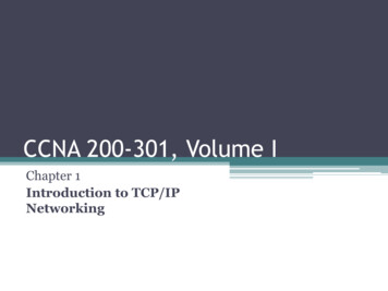
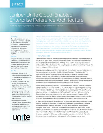
24Using the Contrail Web UI to Enable and Launch an SR-IOV Virtual MachineTo use the Contrail Web UI to enable and launch an SR-IOV VM:1. At Configure Networking Networks, create a virtual network with SR-IOV enabled. Ensure thevirtual network is created with a subnet attached. In the Advanced section, select the Provider Networkcheck box, and specify the physical network already enabled for SR-IOV (in testbed.py or nova.conf)and its VLAN ID. See Figure 1 on page 24.Figure 1: Edit Network2. On the virtual network, create a Neutron port (Configure Networking Ports), and in the Port Bindingsection, define a Key value of SR-IOV and a Value of direct. See Figure 2 on page 25.
25Figure 2: Create Port3. Using the UUID of the Neutron port you created, use the nova boot command to launch the VM fromthat port.nova boot --flavor m1.large --image image name --nic port-id uuid of above port vm name Using the CLI to Enable and Launch SR-IOV Virtual MachinesTo use CLI to enable and launch an SR-IOV VM:1. Create a virtual network with SR-IOV enabled. Specify the physical network already enabled for SR-IOV(in testbed.py or nova.conf) and its VLAN ID.The following example creates vn1 with a VLAN ID of 100 and is part of physnet1:neutron net-create --provider:physical network physnet1 --provider:segmentation id 100 vn12. Create a subnet in vn1.neutron subnet-create vn1 a.b.c.0/24
263. On the virtual network, create a Neutron port on the subnet, with a binding type of direct.neutron port-create --fixed-ip subnet id subnet uuid ,ip address IP address from above subnet --name name of port vn uuid --binding:vnic type direct4. Using the UUID of the Neutron port created, use the nova boot command to launch the VM from thatport.nova boot --flavor m1.large --image image name --nic port-id uuid of above port vm name 5. Log in to the VM and verify that the Ethernet controller is VF by using the lspci command to list thePCI buses.The VF that gets configured with the VLAN can be observed using the ip link command.RELATED DOCUMENTATIONConfiguring the Data Plane Development Kit (DPDK) Integrated with Contrail vRouter 14Optimizing DPDK vRouter Performance Through FullCPU Partitioning and IsolationContrail Networking Release 2003 supports full CPU partitioning. CPU isolation is an RHEL method topartition and isolate the CPU cores on a compute node from the symmetric multiprocessing (SMP) balancingand scheduler algorithms. The full CPU isolation feature optimizes the performance of DPDK vRouterwhen deployed with the DPDK settings recommended for RHOSP.CPU isolation helps isolate forwarding cores, VNF cores, and service cores so that VNF threads and servicethreads do not send processing requests to forwarding cores. By applying CPU isolation, you can allocatededicated forwarding cores to the DPDK VM and ensure that other processes do not send processingrequests to the cores allocated to DPDK vRouter, which in turn improves the
Table3:TextandSyntaxConventions(continued) Convention Description Examples communitynamemembers[community-ids] Enclosesavariableforwhichyoucan substituteoneormorevalues.