Transcription
Contrail Networking Architecture GuideDetailed Technical Description of the Contrail Virtual Networkingand Security PlatformNovember 2019
Juniper Networks, Inc.1133 Innovation WaySunnyvale, California 94089USA408-745-2000www.juniper.netJuniper Networks, the Juniper Networks logo, Juniper, and Junos are registered trademarks of Juniper Networks, Inc. and/or its affiliates in the United States and othercountries. All other trademarks may be property of their respective owners.Juniper Networks assumes no responsibility for any inaccuracies in this document. Juniper Networks reserves the right to change, modify, transfer, or otherwise revise thispublication without notice.The information in this document is current as of the date on the title page.END USER LICENSE AGREEMENTThe Juniper Networks product that is the subject of this technical documentation consists of (or is intended for use with) Juniper Networks software. Use of such software issubject to the terms and conditions of the End User License Agreement (“EULA”) posted at https://www.juniper.net/support/eula/.By downloading, installing or using such software, you agree to the terms and conditions of that EULA.Copyright 2019 Juniper Networks, Inc. All rights reserved.The information in this document is current as of the date on the title page.YEAR 2000 NOTICEJuniper Networks hardware and software products are Year 2000 compliant. Junos OS has no known time-related limitations through the year 2038. However, the NTPapplication is known to have some difficulty in the year 2036.END USER LICENSE AGREEMENTThe Juniper Networks product that is the subject of this technical documentation consists of (or is intended for use with) Juniper Networks software. Use of such software issubject to the terms and conditions of the End User License Agreement (“EULA”) posted at https://support.juniper.net/support/eula/. By downloading, installing or using suchsoftware, you agree to the terms and conditions of that EULA. 2019 Juniper Networks, Inc.2
Table of ContentsIntroduction . 5Use Cases . 5Key Features of Contrail Networking for Virtual Machines and Containers . 6How Contrail Networking Works. 7Contrail Networking Working with An Orchestrator. 7Interaction With An Orchestrator . 9Architecture Details of vRouter . 11Detailed Packet Processing Logic In a vRouter. 13Packet Flow Between VMs In The Same Subnet . 15Packet Flow Between VMs In Different Subnets. 16Service Chains . 16Basic Service Chain . 18Scaled-out Services . 18Policy-based Steering . 19Active-Standby Service Chains . 19Application-based Security Policies . 19Deployment Options for vRouter . 25Kernel Module vRouter . 26DPDK vRouter . 27SR-IOV (Single Root – Input/Output Virtualization) . 27Smart NIC vRouter . 27Contrail Controller Microservices . 27OpenStack Orchestration with Contrail Networking . 28Kubernetes Container Orchestration with Contrail Networking . 30Contrail Networking and VMware vCenter . 34Nested Kubernetes with OpenStack or vCenter . 36Connecting to Physical Networks . 37BGP-Enabled Gateway. 37Source NAT . 39Routing in Underlay . 39Fabric Management in Contrail Networking . 39Scope of Fabric Management . 39 2019 Juniper Networks, Inc.3
Key Concepts Used in Fabric Lifecycle Management . 42Roles . 42Namespaces . 43Virtual Port Groups . 44Procedure for Fabric Creation . 44Fabric Creation . 44Device Discovery . 45Role Assignment . 45Autoconfiguration . 46Device Operations . 46Lifecycle Management and Virtual Networking for Bare Metal Servers. 46Virtual Networking for Physical Servers . 48Packets Between Servers in the Same Virtual Network . 48Packets Between Servers in Different Networks. 49Traffic Between a Physical Server and a VM in the Same Virtual Network . 50Traffic Between a Physical Server and a VM in Different Virtual Networks . 51Physical Network Configuration for VMware vCenter. 52CVFM Design Overview . 52 2019 Juniper Networks, Inc.4
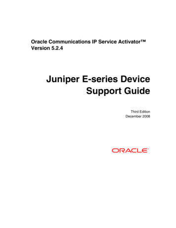
IntroductionIntroductionThis document describes how Contrail Networking provides a scalable virtual networking platform thatworks with a variety of virtual machine and container orchestrators, and can integrate with physicalnetworking and compute infrastructure. This allows users to take advantage of open-sourceorchestration while preserving existing infrastructure, procedures, and workloads, which mitigatesdisruption and cost.As virtualization becomes a key technology for delivery of both public and private cloud services,issues of network scale are becoming apparent with the virtualization technologies that have been inwidespread use to date (E.g. VMware with L2 networking, and OpenStack with stock Nova, Neutronor ML2 networking). Contrail Networking provides a highly scalable virtual networking platform that isdesigned to support multitenant networks in the largest environments while supporting multipleorchestrators simultaneously.Since there are very few datacenter deployments that are truly “greenfield”, there are nearly alwaysrequirements to integrate workloads deployed on new infrastructure with workloads and networks thathave been previously deployed. This document describes a set of scenarios for deployments wherenew cloud infrastructure will be deployed, and where coexistence with existing infrastructure is alsoneeded.Use CasesThe following common use cases are covered in this document: Enable Platform-as-a-Service and Software-as-a-Service with high scalability and flexibility inOpenStack-managed datacentersVirtual networking with container management systems such as Kubernetes, including withRed Hat OpenShiftAllow an existing virtualized environment running VMware vCenter to use Contrail Networkingvirtual networking between virtual machinesConnect Contrail Networking virtual networks to physical networks using gateway routers withBGP peeringProvide lifecycle management for devices in a IP fabric, including zero-touch provisioning,base configuration, underlay configuration, and overlay configurationProvide lifecycle management for bare metal servers, including OS provisioning andattachment into virtual networks by configuring VXLAN VTEPs in connected switchesThese use cases can be deployed in any combination to address the specific requirements in avariety of deployment scenarios. Figure 1, below, illustrates the main feature areas of ContrailNetworking. 2019 Juniper Networks, Inc.5
IntroductionFigure 1: High-level schematic showing the main features of Contrail NetworkingThe key feature areas that enable support of the main use cases are: Virtual networking using encapsulation tunnels between virtualized hostsPlugins for open-source orchestrators for virtual machines and containersApplication-based security policies based on tagsIntegration with VMware orchestration stackLifecycle management for switches and routers in data center fabricsSince the same controller and forwarding components are used in these use cases, ContrailNetworking can provide a consistent interface for managing connectivity in all the environments itsupports, and is able provide seamless connectivity between workloads managed by differentorchestrators, whether virtual machines, containers, or bare metal servers, and to destinations inexternal networks.Key Features of Contrail Networking for Virtual Machines and ContainersContrail Networking manages and implements virtual networking in cloud environments usingOpenStack, Kubernetes and VMware orchestrators. Contrail Networking uses overlay networksbetween vRouters that run on each host. It is based on proven, standards-based networkingtechnologies that today support the wide-area networks of the world’s major service providers, butrepurposed to work in data centers with virtualized workloads and cloud automation. It provides manyenhanced features over the native networking implementations of orchestrators, including: Highly scalable, multitenant networkingMultitenant IP address managementDHCP, ARP proxies to avoid flooding into networks 2019 Juniper Networks, Inc.6
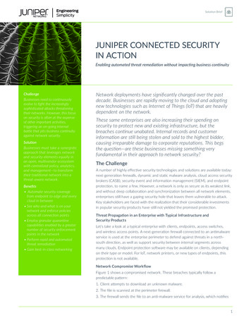
How Contrail Networking Works Local DNS resolutionDistributed firewall with access control listsApplication-based security policiesDistributed load balancing across hostsNetwork address translation (1:1 floating IPs and N:1 SNAT)Service chaining with virtual network functionsDual stack IPv4 and IPv6BGP peering with gateway routersThe following sections describe in detail how the controller interacts with an orchestrator and thevRouters, and how the above features are implemented and configured in each vRouter.Fabric and bare metal server management with Contrail Networking is described in the section FabricManagement in Contrail Networking, later in this document.How Contrail Networking WorksThis section describes the software architecture of the Contrail Networking controller and of thevRouter, which forwards packets in each host, and describes the interaction between vRouters andthe Contrail Networking controller when virtual machines or containers are started and then exchangepackets with each other.Contrail Networking Working with An OrchestratorContrail Networking consists of two primary pieces of software: Contrail Networking Controller – a set of software services that maintains a model of networksand network policies, typically running on several servers for high availabilityContrail Networking vRouter – installed in each virtualized host to enforce network and securitypolicies, and to perform packet forwardingA typical deployment of Contrail Networking is shown in Figure 2, below. 2019 Juniper Networks, Inc.7
How Contrail Networking WorksFigure 2: Contrail Networking uses encapsulation tunnels between virtual workloadsThe Contrail Networking controller is integrated with a cloud management system such as OpenStackor Kubernetes, and its function is to ensure that when a virtual machine (VM) or container is created,it has network connectivity according to the network policies specified in the controller or orchestrator.The Contrail Networking controller integrates with the orchestrator via a software plugin thatimplements the networking service of the orchestrator. For instance, the Contrail Networking pluginfor OpenStack implements the Neutron API, and the kube-network-manager and CNI (containernetwork interface) components listen to network-related events using the Kubernetes (K8s) API.The Contrail Networking vRouter replaces Linux bridge and the iptables utility, or Open vSwitchnetworking, on the compute hosts, and the controller configures the vRouters to implement thedesired networking and security policies.Packets from a VM on one host that have a destination running on a different host are encapsulatedin MPLS over UDP, MPLS over GRE, or VXLAN where the destination of the outer header is the IPaddress of the host that the destination VM is running on. The controller is responsible for installingthe set of routes in each VRF of each vRouter that implements network policies. E.g. by default, VMsin the same network can communicate with each other, but not with VMs in different networks, unless 2019 Juniper Networks, Inc.8
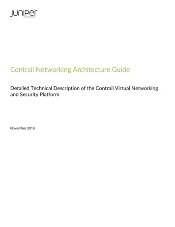
How Contrail Networking Worksthis is specifically enabled in a network policy. Communication between the controller and vRouters isvia XMPP, a widely used and flexible messaging protocol.A key feature of cloud automation is that users can request resources for their applications withoutneeding to understand details of how or even where resources will be provided. This is normally donevia a portal that presents a set of service offerings from which a user can select, and which gettranslated into API calls into underlying systems including the cloud orchestrator to spin up virtualmachines or containers with the necessary memory, disk, and CPU capacity for the user’srequirements. Service offerings can be as simple as a VM with specific memory, disk, and CPUallocated to it, or may include an entire application stack composed of multiple pre-configuredsoftware instances.Interaction With An OrchestratorThe architecture of the Contrail Networking controller and vRouter, and the interaction with anorchestrator, is shown in Figure 3, below.Figure 3: Interaction between an orchestrator, Contrail Networking Controller and Contrail Networking vRouter 2019 Juniper Networks, Inc.9
How Contrail Networking WorksEach interface of VMs running on the host is connected to a VRF that contains the forwarding tablesfor the corresponding network that contains the IP address of that interface. A vRouter only has VRFsfor networks that have interfaces in them on that host, including the Fabric VRF that connects to thephysical interface of the host. Contrail Networking virtual networking uses encapsulation tunneling totransport packets between VMs on different hosts, and the encapsulation and decapsulation happensbetween the Fabric VRF and the VM VRFs. This is explained in more detail in the next section.When a new virtual workload is created, an event is seen in the plugin and sent into the controller,which then sends requests to the agent for routes to be installed in the VRFs for virtual networks, andthe agent then configures them in the forwarder.The logical flow for configuring networking on a new VM with a single interface is as follows:1. Networks and network policies are defined in either the orchestrator or ContrailNetworking using UI, CLI, or REST API. A network is primarily defined as a pool of IPaddresses which will be allocated to interfaces when VMs are created.2. VM is requested to be launched by a user of the orchestrator, including which networkits interface is in.3. The orchestrator selects a host for the new VM to run on, and instructs the computeagent on that host to fetch its image and start the VM.4. The Contrail Networking plugin receives events or API calls from the networking serviceof the orchestrator instructing it to set up the networking for the interface of the new VMthat will be started. These instructions are converted into Contrail Networking RESTcalls and sent to the Contrail Networking controller.5. The Contrail Networking controller sends a request to the vRouter agent for the new VMvirtual interface to be connected to the specified virtual network. The vRouter agentinstructs the vRouter Forwarder to connect the VM interface to the VRF for the virtualnetwork. The VRF is created, if not present, and the interface is connected to it.6. The compute agent starts the VM which will usually be configured to request IPaddresses for each of its interfaces using DHCP. The vRouter proxies the DHCPrequests and responds with the interface IP, default gateway, and DNS serveraddresses.7. Once the interface is active and has an IP address from DHCP, the vRouter will installroutes to the VM’s IP and MAC addresses with a next hop of the VM virtual interface.8. The vRouter assigns a label for the interface and installs a label route in the MPLStable. The vRouter sends an XMPP message to the controller containing a route to thenew VM. The route has a next hop of the IP address of the server that the vRouter is 2019 Juniper Networks, Inc.10
How Contrail Networking Worksrunning on, and specifies an encapsulation protocol using the label that was justallocated.9. The controller distributes the route to the new VM to the other vRouters with VMs in thesame network and in other networks, as allowed by network policy.10. The controller sends routes for the other VMs, as allowed by policy, to the vRouter ofthe new VM.At the end of this procedure, the routes in the VRFs of all the vRouters in the data center have beenupdated to implement the configured network policies, taking account of the new VM.Architecture Details of vRouterThis section describes the architecture of the Contrail Networking vRouter in more detail. Aconceptual view of the functional components of the Contrail Networking vRouter is shown in Figure4, below. 2019 Juniper Networks, Inc.11
How Contrail Networking WorksFigure 4: OpenStack and Contrail Networking agents on a compute nodeThe vRouter agent runs in the user space of the host operating system, while the forwarder can runas a kernel module, in user space when DPDK is used, or can run in a programmable networkinterface card, also known as a “smart NIC”. These options are described in more detail in the sectionDeployment Options for vRouter. The more commonly used kernel module option is illustrated here.The agent maintains a session with the controller and is sent information about VRFs, routes, andaccess control lists (ACLs) that it needs. The agent stores the information in its own database anduses the information to configure the forwarder. Interfaces get connected into VRFs, and theforwarding information base (FIB) in each VRF is configured with forwarding entries.Each VRF has its own forwarding and flow tables, while the MPLS and VXLAN tables are globalwithin the vRouter. The forwarding tables contain routes for both the IP and MAC addresses ofdestinations and the IP-to-MAC association is used to provide proxy ARP capability. The values of 2019 Juniper Networks, Inc.12
How Contrail Networking Workslabels in the MPLS table are selected by the vRouter when VM interfaces come up, and are onlylocally significant to that vRouter. The VXLAN network identifiers are global across all the VRFs of thesame virtual network in different vRouters within a Contrail Networking domain.Detailed Packet Processing Logic In a vRouterThe logic details for packets flowing from a VM, and into a VM, are slightly different and described inFigure 5 and Figure 6.Figure 5: Logic for a packet arriving in a vRouter from a VM interface 2019 Juniper Networks, Inc.13
How Contrail Networking WorksWhen a packet is sent from a VM through a virtual interface, it is received by the forwarder, which firstchecks if there is an entry matching the packets’ 5-tuple (protocol, source and destination IPaddresses, source and destination TCP or UDP ports) in the flow table of the VRF that the interface isin. There won’t be an entry if this is the first packet in a flow, and the forwarder sends the packet tothe agent over the pkt0 interface. The agent determines the action for the flow based on the VRFrouting table and access control list, and updates the flow table with the result. The actions can beDROP, FORWARD or NAT. If the packet is to be forwarded, the forwarder checks to see if thedestination MAC address is its own MAC address, which will be the case if the VM is sending apacket to the default gateway when the destination is outside the VM’s subnet. In that case, the nexthop for destination is looked up in the IP forwarding table, otherwise the MAC address is used forlookup.Figure 6: Logic for a packet arriving in a vRouter from the physical network 2019 Juniper Networks, Inc.14
How Contrail Networking WorksWhen a packet arrives from the physical network, the vRouter first checks if the packet has asupported encapsulation or not. If not, the packet is sent to the host operating system. For MPLS overUDP and MPLS over GRE, the label identifies the VM interface directly, but VXLAN requires that thedestination MAC address in the inner header be looked up in the VRF identified by the VXLANnetwork identifier (VNI). Once the interface is identified, the vRouter can forward the packetimmediately if there is no policy flag set for the interface (indicating that all protocols and all TCP/UDPports are permitted). Otherwise the 5-tuple is used to look up the flow in the flow table and the samelogic as described for an outgoing packet is used.Packet Flow Between VMs In The Same SubnetThe sequence of action that occurs when a VM first sends a packet to another VM is shown in thefollowing diagram. The starting point is that both VMs have booted and the controller has sent L2(MAC) and L3 (IP) routes to both vRouters to enable communication between the VMs.Figure 7: Sequence when a VM sends a packet to another VM1. VM1 needs to send a packet to VM2, so first looks up its own DNS cache for the IP address,but since this is the first packet, there is no entry.2. VM1 sends a DNS request to the DNS server address that was supplied in the DHCPresponse when its interface came up.3. The vRouter traps the DNS request and forwards it to the DNS server running in the ContrailNetworking controller. 2019 Juniper Networks, Inc.15
Service Chains4. The DNS server in the controller responds with the IP address of VM2.5. The vRouter sends the DNS response to VM1.6. VM1 needs to form an Ethernet frame, so needs the MAC address for VM2. It checks its ownARP cache, but there is no entry, since this is the first packet.7. VM1 sends out an ARP request.8. The vRouter traps the ARP request and looks up the MAC address for IP-VM2 in its ownforwarding tables and find the association in the L2/L3 routes that the controller sent it for VM2.9. The vRouter sends an ARP reply to VM1 with the MAC address of VM2.10. A TCP timeout occurs in the network stack of VM1.11. The network stack of VM1 retries sending the packet, and this time finds the MAC address ofVM2 in the ARP cache and can form an Ethernet frame and send it out.12. The vRouter looks up the MAC address for VM2 and finds an encapsulation route. ThevRouter builds the outer header and sends the resulting packet to S2.13. The vRouter on S2 decapsulates the packet and looks up the MPLS label to identify the virtualinterface to send the original Ethernet frame into. The Ethernet frame is sent into the interfaceand received by VM2.Packet Flow Between VMs In Different SubnetsThe sequence when sending packets to destinations in a different subnet is identical except that VM1will send the packet in an Ethernet frame with the MAC address of the default gateway, whose IPaddress was supplied in the DHCP response that the vRouter supplied when VM1 booted. WhenVM1 does an ARP request for the gateway IP address, the vRouter responds with its own MACaddress. When VM1 sends an Ethernet frame using that gateway MAC address, the vRouter usesthe destination IP address of the packet inside the frame to look up the forwarding table in the VRF tofind a route, which will be via an encapsulation tunnel to the host that the destination VM is runningon.Service ChainsA service chain is formed when a network policy specifies that traffic between two networks has toflow through one or more network services, also termed Virtual Network Functions (VNF). Thenetwork services are implemented in VMs—identified in Contrail Networking as services—which arethen included in policies. Contrail Networking supports service chains in both OpenStack and vCenterenvironments. The concept of service chaining between two VMs is shown in Figure 8. 2019 Juniper Networks, Inc.16
Service ChainsFigure 8: Special routes direct traffic through a VNF in a service chainWhen a VM is configured in the controller to be a service instance (VNF), and the service is includedin a network policy that is applied to networks the policy refers to, the controller installs routes in theVRFs of the “Left” and “Right” interfaces of the VNF that direct traffic through the VNF. Whenencapsulation routes are advertised by the VNF vRouter back to the controller, the routes aredistributed to other vRouters that have Red and Green VRFs and the end result is a set of routes thatdirect traffic flowing between the Red and Green networks to pass through the service instance. Thelabels “Left” and “Right” are used to identify interfaces based on the order that they become activewhen the VNF is booted. The VNF must have a configuration that will process packets appropriatelybased on the interfaces that they will arrive on.As implemented in Contrail Networking, service chain routes are installed in special VRFs that, forclarity, are not shown here, but the principle is the same. 2019 Juniper Networks, Inc.17
Service ChainsVarious service chain scenarios are illustrated in Figure 9, below, and a brief explanation of eachfollows.Figure 9: Containers connected with Contrail NetworkingBasic Service ChainIn the first panel, a simple service chain has been created by editing the network policy between theRed and Green networks to include the services FW and DPI. These are VMs that were previouslystarted in OpenStack or vCenter and then configured in Contrail Networking to be service instanceswith interfaces in the Red and Green networks. When the policy is saved and is applied to the twonetworks, the routes in all the vRouters with Red or Green VMs attached are modified to send trafficbetween the two net
vRouter, which forwards packets in each host, and describes the interaction between vRouters and the Contrail Networking controller when virtual machines or containers are started and then exchange packets with each other. Contrail Networking Working with An Orchestrator . Contrail Networking consists of two primary pieces of software: