Transcription
Technical Report Documentation Page1. Report No.2. Government Accession No.3. Recipient's Catalog No.FHWA/TX-07/0-5547-14. Title and Subtitle5. Report DateINTERMEDIATE ACCESS TO BUFFER-SEPARATED MANAGEDLANESSeptember 2006Resubmitted: November 2006Resubmitted: February 2007Published: March 20076. Performing Organization Code7. Author(s)8. Performing Organization Report No.Kay Fitzpatrick, Marcus A. Brewer, and Eun Sug ParkReport 0-5547-19. Performing Organization Name and Address10. Work Unit No. (TRAIS)Texas Transportation InstituteThe Texas A&M University SystemCollege Station, Texas 77843-313511. Contract or Grant No.12. Sponsoring Agency Name and Address13. Type of Report and Period CoveredTexas Department of TransportationResearch and Technology Implementation OfficeP. O. Box 5080Austin, Texas 78763-5080Technical Report:September 2005-August 2006Project 0-554714. Sponsoring Agency Code15. Supplementary NotesProject performed in cooperation with the Texas Department of Transportation and the Federal HighwayAdministration.Project Title: Best Practices for Access between Toll Lanes and Free LanesURL: http://tti.tamu.edu/documents/0-5547-1.pdf16. AbstractThe objective of this Texas Department of Transportation (TxDOT) research project was to developguidance materials on intermediate access to a buffer-separated toll lane. To develop the material,researchers gathered other state guidelines, reviewed the literature, and recorded operations at fiveintermediate access sites. From videotapes of the sites, characteristics of approximately 8400 vehicles thatmoved into or out of the managed lane were recorded. Examples of the characteristics measured includedwhere the vehicle entered or left the lane (early, within the opening, or late) and the lane of origin for thevehicle. Volume counts for 5-minute periods were associated with each maneuver. Approximately9 percent of the vehicles crossed the solid white markings (i.e., were not in compliance with the pavementmarkings). Compliance was better for the longer access opening length (1500 ft) as compared to the 1160-ftaccess opening length. A surprisingly large number of maneuvers at the intermediate access openings (over7 percent) involve vehicles passing slower-moving vehicles. At the two sites with the larger quantity ofdata between 40 and 80 percent of the passing vehicles involved a vehicle leaving the managed lane to passa slower-moving managed-lane vehicle. Findings from one field site demonstrated that when presentedwith the opportunity to enter a managed lane that is located very close to an entrance ramp, drivers willattempt to cross multiple lanes to do so.17. Key Words18. Distribution StatementIntermediate Access, Managed Lanes, BufferSeparation, Weaving ManeuversNo restrictions. This document is available to thepublic through NTIS:National Technical Information ServiceSpringfield, Virginia 22161http://www.ntis.gov19. Security Classif.(of this report)20. Security Classif.(of this page)21. No. of PagesUnclassifiedUnclassified106Form DOT F 1700.7 (8-72)Reproduction of completed page authorized22. Price
INTERMEDIATE ACCESS TO BUFFER-SEPARATEDMANAGED LANESbyKay Fitzpatrick, Ph.D., P.E.Research EngineerTexas Transportation InstituteMarcus A. Brewer, P.E.Assistant Research EngineerTexas Transportation InstituteandEun Sug Park, Ph.D.Associate Research ScientistTexas Transportation InstituteReport 0-5547-1Project 0-5547Project Title: Best Practices for Access between Toll Lanes and Free LanesPerformed in cooperation with theTexas Department of Transportationand theFederal Highway AdministrationSeptember 2006Resubmitted: November 2006Resubmitted: February 2007Published: March 2007TEXAS TRANSPORTATION INSTITUTEThe Texas A&M University SystemCollege Station, Texas 77843-3135
DISCLAIMERThe contents of this report reflect the views of the authors, who are responsible for thefacts and the accuracy of the data presented herein. The contents do not necessarily reflect theofficial view or policies of the Federal Highway Administration (FHWA) or the TexasDepartment of Transportation. This report does not constitute a standard, specification, orregulation. The engineer in charge was Kay Fitzpatrick, P.E. (TX-86762).v
ACKNOWLEDGMENTSThis project was conducted in cooperation with TxDOT and FHWA.The authors thank the members of TxDOT’s Project Monitoring Committee for theirguidance during the study: Joseph Carrizales, Austin District, TxDOT, Project Director Bob Daigh, Austin District, TxDOT, Program Coordinator Christine Conner, Austin District, Project Advisor Linda Blume-Grimsely, San Antonio District, Project Advisor Wade Odell, Research and Technology Implementation Office, TxDOT, ResearchEngineerThe following individuals assisted the research team in identifying sites or incoordinating the data collection at a specific site. Their assistance contributed to the success ofthis project and their aid is greatly appreciated: Jim Mims – Project Manager, Waller/West Harris Area Office, TxDOT HoustonDistrict Daniel Loving – ITS Analyst, DalTrans Traffic Management Center, TxDOT DallasDistrict Deborah Allen – Control Center Operator, DalTrans Traffic Management Center,TxDOT Dallas District Rick Cortez – Freeway Management Engineer, DalTrans Traffic Management Center,TxDOT Dallas District Nick Thompson – Operations Manager, Minnesota Department of Transportation(MnDOT) Grant Schultz – Assistant Professor, Brigham Young University David Schwartz – Utah Department of Transportation, Region 2vi
The following TxDOT personnel assisted the research team with reviews of the pavementmarkings proposed for the guidelines. Their assistance in understanding the tradeoffs betweendifferent markings is appreciated: Michael Chacon, Traffic Operations Division, TxDOT Doug Skowronek, Traffic Operations Division, TxDOTAssisting the authors of the report in collecting and reducing data or in analyzing the datawere the following Texas Transportation Institute (TTI) staff: Sara Roby, Student Worker Curtis White, Student Worker Ivan Lorenz, Associate Research Specialist Todd Hausman, Associate Research Specialist Jim Carvell, Senior Research Engineer Ginger Goodin, Research Engineervii
viii
TABLE OF CONTENTSLIST OF FIGURES . xiLIST OF TABLES . xiiiCHAPTER 1 INTRODUCTION . 1RESEARCH OBJECTIVES . 2ORGANIZATION . 3CHAPTER 2 REVIEW OF PREVIOUS RESEARCH. 5BACKGROUND . 5TYPES OF ACCESS TO AND FROM MANAGED LANES . 6Continuous Access. 6Restricted Access – Terminal . 6Restricted Access – Intermediate. 7SAFETY . 10DESIGN OF INTERMEDIATE MANAGED-LANE ACCESS . 12Buffer Opening . 12Buffer Width . 15TRAFFIC CONTROL FOR ACCESS . 16Signing . 16Markings . 18LOCATION OF ACCESS WITH RESPECT TO OTHER RAMPS . 19CHAPTER 3 COLLECTION OF FIELD DATA. 23SITE SELECTION AND EVALUATION. 23MANEUVERS DATA COLLECTION . 26Data Collection with Camcorders. 26Data Collection with TMC Cameras. 36SPEED DATA COLLECTION . 38CHAPTER 4 REDUCTION OF FIELD DATA . 41MANEUVERS DATA. 41Maneuver Characteristics. 42Summary Tables . 46TRAFFIC VOLUME COUNTS . 46SPEED DATA . 47Verification of Accuracy. 48VEHICLE POSITION IN LANE DATA . 48CHAPTER 5 FINDINGS FROM FIELD STUDIES. 51MANEUVERS. 51Compliance with Respect to Access Opening Length. 52Abort Maneuvers . 59Passing Maneuvers. 60Maneuver Time. 64USE OF TURN SIGNAL . 67SPEED . 68Comparison of Speeds between Lane 4 and HOV Lane. 69Time of Day . 70Influence of Congestion and Incidents . 72ix
LOCATION OF ACCESS WITH RESPECT TO ENTRANCE RAMP . 73VEHICLE POSITION WITHIN LANE. 78CHAPTER 6 SUMMARY AND CONCLUSIONS. 83SUMMARY OF RESEARCH. 83CONCLUSIONS. 84Maneuvers. 84Passing Maneuvers. 85Maneuver Time. 85Location of Access with Respect to Other Ramps. 86Vehicle Position within Lane. 86APPENDIX GUIDELINES. 89REFERENCES. 91x
LIST OF FIGURESFigure 1-1. Examples of Separations between Managed Lanes and General-Purpose Lanes. . 1Figure 1-2. Examples of At-Grade Access to Managed Lanes Located within GeneralPurpose Lanes. . 2Figure 2-1. Example of Layouts for Managed Lane Entry Terminal with Slip Ramps (fromManaged Lanes Handbook) (1). . 7Figure 2-2. Buffer-Separated Intermediate Access with and without Weave Lane (fromManaged Lanes Handbook) (1). . 8Figure 2-3. Arrangements for Successive Ramps from TxDOT Roadway Design Manual(Reproduction of Roadway Design Manual Figure 3-37) (3). 10Figure 2-4. Utah I-15 Express Lane Access Design (7, 8). . 13Figure 2-5. Photograph of I-15 Express Lane Opening Transition in Salt Lake City. . 14Figure 2-6. Photograph of I-15 Express Lane Opening in Salt Lake City. 14Figure 2-7. Caltrans Weave Distance at Buffer-Separated HOV Facilities (2). 15Figure 2-8. Example of a Section of the I-394 HOT Lane in Minneapolis (10). 16Figure 2-9. Example of Signing for the Intermediate Entry to and Exit from Barrier- orBuffer-Separated HOV Lanes (Reproduction of TMUTCD Figure 2E-47) (11). . 17Figure 2-10. Example of Striping Pattern for an HOV Lane (12). . 18Figure 2-11. Excerpts from TxDOT Typical Standards for Freeway Pavement Markings,FPM(2)-00A (13). . 19Figure 2-12. Termination of Managed Lane as a “Free” Lane to Inside (1). . 20Figure 3-1. HOV Lanes in Dallas. . 24Figure 3-2. HOV Lanes in Houston. 25Figure 3-3. HOT Lane Access Point on I-394 EB at US-169, Minneapolis, MN. . 26Figure 3-4. Camcorder Installation at Site 1. 28Figure 3-5. Camcorder Installation at Site 3. 29Figure 3-6. Camcorder Field of View at Site 3. 29Figure 3-7. Closed Median Area on I-10 Near Sites 4 and 5. 30Figure 3-8. Camcorder Field of View at Sites 4 and 5. . 30Figure 3-9. I-635 (LBJ Freeway) WB HOV Lane Access at Rosser. 31Figure 3-10. I-35E (Stemmons Freeway) NB HOV Lane Access at Whitlock. . 32Figure 3-11. I-10 (Katy Freeway) EB HOV Lane Access at Fry Road. 33Figure 3-12. I-10 (Katy Freeway) EB HOV Lane Access at Barker-Cypress. 34Figure 3-13. I-394 EB HOV Lane Access at US-169. 35Figure 3-14. Image from Dallas TMC Camera on I-635 EB at Josey (18). . 36Figure 3-15. Image from MnDOT Camera on I-394 EB at US-169, Minneapolis, MN (19). 37Figure 3-16. Spot Speed Data Collection at Site 1. . 38Figure 3-17. Spot Speed and Distance Readout from Laser Gun at Site 1. 39Figure 4-1. Sample Image of Video for Maneuvers Data. 43Figure 4-2. Division of Access Opening and Lane Assignments at Site 1. . 44Figure 4-3. Example of Shifting Vehicle Position in HOV Lane Near Access Opening. . 49Figure 4-4. Example of Shifting Vehicle Position in Adjacent General-Purpose Lane NearAccess Opening. . 50Figure 5-1. Mosaic Plot of Proportion of Maneuvers by Zone. 54xi
Figure 5-2. Mosaic Plot of Proportion of Maneuver by Zone for Sites with 1100, 1160,and 1500 ft Access Opening Lengths. . 57Figure 5-3. Mosaic Plot of Proportion of Maneuver by Compliance for Sites with 1160and 1500 ft Access Opening Lengths. . 58Figure 5-4. Percent of Maneuvers Involving a Pass or Abort. 61Figure 5-5. Proportion of Passing Vehicles to 5-Minute HOV Lane Volume. 63Figure 5-6. Proportion of Passing Vehicles to 5-Minute Adjacent General-Purpose LaneVolume. 64Figure 5-7. Percent of Maneuvers for Different Maneuver Times by 5-Minute HOVLane Count. 66Figure 5-8. Percent of Maneuvers for Different Maneuver Times by 5-Minute AdjacentLane Count. 67Figure 5-9. Use of Turn Signal. . 68Figure 5-10. Individual Speeds in Lane 4 by Time of Day. . 71Figure 5-11. Individual Speeds in the HOV Lane by Time of Day. 71Figure 5-12. Example of Cross-Facility Weave from Ramp to HOV Lane. . 74Figure 5-13. 85th Percentile Speeds on Lane 4 and HOV Lane during Ramp-to-HOV LaneManeuvers. 77Figure 5-14. Vehicle Location When Dataset Contains Only Passenger Cars. . 79Figure 5-15. Vehicle Location When Dataset Contains Heavy Trucks in Lane 4. 81Figure A-1. Intermediate Access Opening. 90xii
LIST OF TABLESTable 2-1. Weaving Distances for Managed Lane Cross-Freeway Maneuvers fromManaged Lanes Handbook (1). . 20Table 3-1. Summary of Maneuvers Data Collected. 27Table 4-1. Summary of Site Characteristics. . 42Table 4-2. Sample of Spreadsheet Containing Reduced Maneuvers Data. . 45Table 4-3. Summary of Maneuvers Data Reduced. 46Table 4-4. Summary of Speed Data Collected. 47Table 4-5. Sample of Reduced and Formatted Speed Data. . 48Table 5-1. Number of Maneuvers by Site. 52Table 5-2. Number of Maneuvers by Site and by Zone. 53Table 5-3. Results from Evaluation of Access Zones Difference for All Sites. . 55Table 5-4. Results from Evaluation of Access Zones Difference for Sites with 1100,1160, and 1500 ft Access Opening Lengths. 56Table 5-5. Results from Evaluation of Compliance Difference for Sites with 1160 and1500 ft Access Opening Lengths. 59Table 5-6. Percent of Passing Vehicles. 60Table 5-7. Results from Logistic Evaluation of Passing Probability. 62Table 5-8. Average Maneuver Time per Site and Lane Origin. . 65Table 5-9. Number of Vehicles included in Speed Datasets. . 68Table 5-10. Comparison of Speed Data for May 8 Off-Peak Period. 69Table 5-11. Comparison of Speed Data for May 8 PM Peak Period. 70Table 5-12. Comparison of Behavior during High- and Low-Speed Periods. 73Table 5-13. Number of Vehicles Weaving from Ramp to HOV Lane Observed duringStudy. 75Table 5-14. Approximate Distance Traveled by Ramp Vehicle Entering HOV Lane. . 76Table 5-15. Vehicle Counts during Ramp-to-HOV Lane Maneuvers. . 78Table 5-16. Vehicle Location within Lanes When Dataset Contains Only Passenger Cars. 79Table 5-17. Vehicle Location within Lanes When Dataset Contains Heavy Trucks inLane 4. . 81xiii
xiv
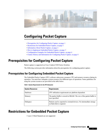
CHAPTER 1INTRODUCTIONAgencies have installed various types of treatments to separate interior managed lanesfrom general-purpose lanes at existing projects (see Figure 1-1) and are looking at options forfuture projects. Interior managed lanes can include high-occupancy vehicle (HOV) lanes, tolllanes, and high occupancy toll (HOT) lanes. The treatments to separate the managed lanes fromthe general-purpose lanes must include access points, they must control traffic, and they mustperform at an acceptable level of safety. Some of the treatments are more costly in constructionor maintenance, while others are a hindrance to emergency access. The aesthetics of thetreatment along with their cross section needs are other factors considered during selection.(a) Barrier Separation(b) Pylon Separation(c) Solid Line Separation(d) Dashed Line SeparationFigure 1-1. Examples of Separations between Managed Lanes and General-Purpose Lanes.1
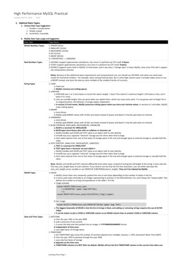
Access to these interior managed lanes has been achieved using elevated ramps and atgrade ramps. At-grade access includes intermediate access and slip ramp terminal access withexamples shown in Figure 1-2. In this project the research focused on the investigation ofintermediate at-grade access. Previous work has investigated when a direct access ramp shouldbe considered rather than an at-grade access point. At-grade access is also more in concert withthe use of delineators and pavement markings as separators rather than raised concrete barriers.(a) Intermediate Access(b) Slip Ramp AccessFigure 1-2. Examples of At-Grade Access to Managed Lanes Located within GeneralPurpose Lanes.RESEARCH OBJECTIVESThe objective of the project was to develop guidance suitable for use by an engineer ordesigner in decisions related to providing access to and from toll lanes located within generalpurpose lanes (GPL). The Appendix of this report includes draft materials that could beincorporated into a TxDOT publication.Additional objectives for this research project that supported the development ofguidance material included the following: Identify the location where drivers are entering or exiting a managed lane locatedwithin general-purpose lanes.2
Determine whether the location where the vehicle is entering or exiting varies as afunction of access opening length, type of maneuver, or amount of traffic present. Record speed performance of drivers near an access to an internal high-occupancyvehicle lane. Comment on vehicle placement within a lane and whether that placement is affectedby the markings present. Comment on the behavior of drivers moving from an entrance ramp across severallanes to enter an HOV lane at a selected site.ORGANIZATIONThe research findings are presented in six chapters, including this chapter, and theAppendix. A brief summary of the material in each chapter follows: Chapter 1: Introduction contains a brief overview of the project. It also explains theresearch objectives and provides an overview of the contents of the report. Chapter 2: Review of Previous Research presents a summary of previous work. Chapter 3: Collection of Field Data discusses the methodology used to collect thefield data. Chapter 4: Reduction of Field Data presents the procedure used to create thedatasets used in the evaluations. Chapter 5: Findings from Field Studies presents the results from analyzing thedata obtained during field studies. Chapter 6: Summary and Conclusions summarizes the project and presents theconclusions from the project. Appendix: Guidelines present draft materials that can be included in TxDOTpublications or the Managed Lanes Handbook (1).3
4
CHAPTER 2REVIEW OF PREVIOUS RESEARCHBACKGROUNDIn this project the research focused on the investigation of issues associated withintermediate at-grade access. At-grade access is more in concert with the use of delineators andpavement markings as separators. Within this portion of the project, researchers reviewedexisting literature and design guidelines to determine the state-of-the-practice regardingintermediate access to and from toll lanes.The number of toll lanes adjacent to or within general-purpose lanes in the United Statesis very small, and there were none in Texas at the time of this research project. Also, stand-alonetoll facilities do not provide the same interaction with vehicles because of their separatedconstruction. However, many of the operational characteristics of adjacent HOV lanes aresimilar to those of toll lanes within general-purpose lanes; therefore, much of the informationpresented here is from HOV lane sources.The types of information gathered by the research team included: General characteristics for similar types of access for HOV and toll lanes. Safety of HOV lanes. Design characteristics of intermediate access including:o buffer opening length, ando buffer width. Traffic control needs for intermediate access by:o signing, ando markings.Following is a summary of information currently known on the topics listed above.5
TYPES OF ACCESS TO AND FROM MANAGED LANESThere are two general approaches to providing access: at-grade access and gradeseparated access. This research project did not investigate grade-separated access issues. Atgrade access represents the most commonly used treatment with concurrent-flow managed lanes.At-grade access can occur at the start or end of the managed lane or at some midpoint along thefacility. Within the facility, the access can be: unrestricted or unlimited (continuous) access, or restricted or limited access.Continuous AccessContinuous access allows eligible vehicles to enter and leave the lane at any point. Noweave, acceleration, or deceleration lane is provided. The striping used to separate the generalpurpose and the managed lanes, along with signing and pavement markings, should all indicatethat access can occur at any point. The unlimited access concept is used in projects where nobuffer separates the managed lane and the general-purpose lanes.Restricted Access – TerminalRestricted or limited access regulates the locations where vehicles can enter and leave amanaged lane. Slip ramps are typically used at terminals, particularly with barrier-separatedfacilities. One benefit of slip ramps is that they provide for ingress or egress but not for bothmovements at the same location, eliminating the need to weave traffic in both directions.Figure 2-1 provides examples of entrance and exit locations with slip ramps from the ManagedLanes Handbook (1).The Managed Lanes Handbook recommends that a managed lane continue as a generalpurpose lane when terminated. If the managed lane volumes do not exceed 1000 vehicles perhour, a merge area of approximately 1500 ft downstream of the slip ramp may be acceptable buteffects on the general-purpose lanes should be checked. It should also be noted that the merge6
tapers in design are desirably 115:1 with a minimum of 60:1, and diverge tap
Texas Transportation Institute The Texas A&M University System College Station, Texas 77843-3135 11. Contract or Grant No. Project 0-5547 13. Type of Report and Period Covered Technical Report: September 2005-August 2006 12. Sponsoring Agency Name and Address Texas Department of Transportation Research and Technology Implementation Office