Transcription
Hyperloop AlphaIntroThe first several pages will attempt to describe the design in everydaylanguage, keeping numbers to a minimum and avoiding formulas and jargon. Iapologize in advance for my loose use of language and imperfect analogies.The second section is for those with a technical background. There are nodoubt errors of various kinds and superior optimizations for elements of thesystem. Feedback would be most welcome – please send tohyperloop@spacex.com or hyperloop@teslamotors.com. I would like to thankmy excellent compadres at both companies for their help in putting thistogether.BackgroundWhen the California “high speed” rail was approved, I was quite disappointed,as I know many others were too. How could it be that the home of SiliconValley and JPL – doing incredible things like indexing all the world’s knowledgeand putting rovers on Mars – would build a bullet train that is both one of themost expensive per mile and one of the slowest in the world? Note, I amPage 1
hedging my statement slightly by saying “one of”. The head of the Californiahigh speed rail project called me to complain that it wasn’t the very slowestbullet train nor the very most expensive per mile.The underlying motive for a statewide mass transit system is a good one. Itwould be great to have an alternative to flying or driving, but obviously only ifit is actually better than flying or driving. The train in question would be bothslower, more expensive to operate (if unsubsidized) and less safe by two ordersof magnitude than flying, so why would anyone use it?If we are to make a massive investment in a new transportation system, thenthe return should by rights be equally massive. Compared to the alternatives, itshould ideally be: SaferFasterLower costMore convenientImmune to weatherSustainably self-poweringResistant to EarthquakesNot disruptive to those along the routeIs there truly a new mode of transport – a fifth mode after planes, trains, carsand boats – that meets those criteria and is practical to implement? Many ideasfor a system with most of those properties have been proposed and should beacknowledged, reaching as far back as Robert Goddard’s to proposals in recentdecades by the Rand Corporation and ET3.Unfortunately, none of these have panned out. As things stand today, there isnot even a short distance demonstration system operating in test pilot modeanywhere in the world, let alone something that is robust enough for publictransit. They all possess, it would seem, one or more fatal flaws that preventthem from coming to fruition.Constraining the ProblemThe Hyperloop (or something similar) is, in my opinion, the right solution forthe specific case of high traffic city pairs that are less than about 1500 km or900 miles apart. Around that inflection point, I suspect that supersonic airtravel ends up being faster and cheaper. With a high enough altitude and theright geometry, the sonic boom noise on the ground would be no louder thancurrent airliners, so that isn’t a showstopper. Also, a quiet supersonic planeimmediately solves every long distance city pair without the need for a vastnew worldwide infrastructure.Page 2
However, for a sub several hundred mile journey, having a supersonic plane israther pointless, as you would spend almost all your time slowly ascending anddescending and very little time at cruise speed. In order to go fast, you need tobe at high altitude where the air density drops exponentially, as air at sea levelbecomes as thick as molasses (not literally, but you get the picture) as youapproach sonic velocity.So What is Hyperloop Anyway?Short of figuring out real teleportation, which would of course be awesome(someone please do this), the only option for super fast travel is to build a tubeover or under the ground that contains a special environment. This is wherethings get tricky.At one extreme of the potential solutions is some enlarged version of the oldpneumatic tubes used to send mail and packages within and between buildings.You could, in principle, use very powerful fans to push air at high speedthrough a tube and propel people-sized pods all the way from LA to SanFrancisco. However, the friction of a 350 mile long column of air moving atanywhere near sonic velocity against the inside of the tube is so stupendouslyhigh that this is impossible for all practical purposes.Another extreme is the approach, advocated by Rand and ET3, of drawing ahard or near hard vacuum in the tube and then using an electromagneticsuspension. The problem with this approach is that it is incredibly hard tomaintain a near vacuum in a room, let alone 700 miles (round trip) of largetube with dozens of station gateways and thousands of pods entering andexiting every day. All it takes is one leaky seal or a small crack somewhere inthe hundreds of miles of tube and the whole system stops working.However, a low pressure (vs. almost no pressure) system set to a level wherestandard commercial pumps could easily overcome an air leak and thetransport pods could handle variable air density would be inherently robust.Unfortunately, this means that there is a non-trivial amount of air in the tubeand leads us straight into another problem.Overcoming the Kantrowitz LimitWhenever you have a capsule or pod (I am using the words interchangeably)moving at high speed through a tube containing air, there is a minimum tube topod area ratio below which you will choke the flow. What this means is that ifthe walls of the tube and the capsule are too close together, the capsule willbehave like a syringe and eventually be forced to push the entire column of airin the system. Not good.Nature’s top speed law for a given tube to pod area ratio is known as theKantrowitz limit. This is highly problematic, as it forces you to either go slowlyPage 3
or have a super huge diameter tube. Interestingly, there are usually twosolutions to the Kantrowitz limit – one where you go slowly and one where yougo really, really fast.The latter solution sounds mighty appealing at first, until you realize that goingseveral thousand miles per hour means that you can’t tolerate even wide turnswithout painful g loads. For a journey from San Francisco to LA, you will alsoexperience a rather intense speed up and slow down. And, when you get rightdown to it, going through transonic buffet in a tube is just fundamentally adodgy prospect.Both for trip comfort and safety, it would be best to travel at high subsonicspeeds for a 350 mile journey. For much longer journeys, such as LA to NY, itwould be worth exploring super high speeds and this is probably technicallyfeasible, but, as mentioned above, I believe the economics would probablyfavor a supersonic plane.The approach that I believe would overcome the Kantrowitz limit is to mountan electric compressor fan on the nose of the pod that actively transfers highpressure air from the front to the rear of the vessel. This is like having a pumpin the head of the syringe actively relieving pressure.It would also simultaneously solve another problem, which is how to create alow friction suspension system when traveling at over 700 mph. Wheels don’twork very well at that sort of speed, but a cushion of air does. Air bearings,which use the same basic principle as an air hockey table, have beendemonstrated to work at speeds of Mach 1.1 with very low friction. In thiscase, however, it is the pod that is producing the air cushion, rather than thetube, as it is important to make the tube as low cost and simple as possible.That then begs the next question of whether a battery can store enough energyto power a fan for the length of the journey with room to spare. Based on ourcalculations, this is no problem, so long as the energy used to accelerate thepod is not drawn from the battery pack.This is where the external linear electric motor comes in, which is simply around induction motor (like the one in the Tesla Model S) rolled flat. Thiswould accelerate the pod to high subsonic velocity and provide a periodicreboost roughly every 70 miles. The linear electric motor is needed for as littleas 1% of the tube length, so is not particularly costly.Making the Economics WorkThe pods and linear motors are relatively minor expenses compared to the tubeitself – several hundred million dollars at most, compared with several billiondollars for the tube. Even several billion is a low number when compared withseveral tens of billion proposed for the track of the California rail project.Page 4
The key advantages of a tube vs. a railway track are that it can be built abovethe ground on pylons and it can be built in prefabricated sections that aredropped in place and joined with an orbital seam welder. By building it onpylons, you can almost entirely avoid the need to buy land by followingalongside the mostly very straight California Interstate 5 highway, with onlyminor deviations when the highway makes a sharp turn.Even when the Hyperloop path deviates from the highway, it will cause minimaldisruption to farmland roughly comparable to a tree or telephone pole, whichfarmers deal with all the time. A ground based high speed rail system bycomparison needs up to a 100 ft wide swath of dedicated land to build upfoundations for both directions, forcing people to travel for several miles justto get to the other side of their property. It is also noisy, with nothing tocontain the sound, and needs unsightly protective fencing to prevent animals,people or vehicles from getting on to the track. Risk of derailment is also notto be taken lightly, as demonstrated by several recent fatal train accidents.Earthquakes and Expansion JointsA ground based high speed rail system is susceptible to Earthquakes and needsfrequent expansion joints to deal with thermal expansion/contraction andsubtle, large scale land movement.By building a system on pylons, where the tube is not rigidly fixed at any point,you can dramatically mitigate Earthquake risk and avoid the need for expansionjoints. Tucked away inside each pylon, you could place two adjustable lateral(XY) dampers and one vertical (Z) damper.These would absorb the small length changes between pylons due to thermalchanges, as well as long form subtle height changes. As land slowly settles to anew position over time, the damper neutral position can be adjustedaccordingly. A telescoping tube, similar to the boxy ones used to accessairplanes at airports would be needed at the end stations to address thecumulative length change of the tube.Can it Really be Self-Powering?For the full explanation, please see the technical section, but the short answeris that by placing solar panels on top of the tube, the Hyperloop can generatefar in excess of the energy needed to operate. This takes into account storingenough energy in battery packs to operate at night and for periods of extendedcloudy weather. The energy could also be stored in the form of compressed airthat then runs an electric fan in reverse to generate energy, as demonstratedby LightSail.Page 5
Hyperloop Preliminary Design StudyTechnical Section1. AbstractExisting conventional modes of transportation of people consists of four uniquetypes: rail, road, water, and air. These modes of transport tend to be eitherrelatively slow (e.g., road and water), expensive (e.g., air), or a combinationof relatively slow and expensive (i.e., rail). Hyperloop is a new mode oftransport that seeks to change this paradigm by being both fast andinexpensive for people and goods. Hyperloop is also unique in that it is an opendesign concept, similar to Linux. Feedback is desired from the community thatcan help advance the Hyperloop design and bring it from concept to reality.Hyperloop consists of a low pressure tube with capsules that are transported atboth low and high speeds throughout the length of the tube. The capsules aresupported on a cushion of air, featuring pressurized air and aerodynamic lift.The capsules are accelerated via a magnetic linear accelerator affixed atvarious stations on the low pressure tube with rotors contained in each capsule.Passengers may enter and exit Hyperloop at stations located either at the endsof the tube, or branches along the tube length.In this study, the initial route, preliminary design, and logistics of theHyperloop transportation system have been derived. The system consists ofcapsules that travel between Los Angeles, California and San Francisco,California. The total one-way trip time is 35 minutes from county line to countyline. The capsules leave on average every 2 minutes from each terminalcarrying 28 people each (as often as every 30 seconds during rush hour and lessfrequently at night). This gives a total of 7.4 million people per tube that canbe transported each year on Hyperloop. The total cost of Hyperloop is under 6billion USD for two one-way tubes and 40 capsules. Amortizing this capital costover 20 years and adding daily operational costs gives a total of 20 USD plusoperating costs per one-way ticket on the passenger Hyperloop.Useful feedback is welcomed on aspects of the Hyperloop design. E-mailfeedback to hyperloop@spacex.com or hyperloop@teslamotors.com.2. Table of Contents1.2.3.4.Abstract .6Table of Contents .6Background .8Hyperloop Transportation System .94.1. Capsule. 11Page 6
4.1.1. Geometry . 134.1.2. Interior . 154.1.3. Compressor . 174.1.4. Suspension . 204.1.5. Onboard Power . 224.1.6. Propulsion . 224.1.7. Cost. 234.2. Tube . 244.2.1. Geometry . 254.2.2. Tube Construction . 274.2.3. Pylons and Tunnels . 284.2.4. Station Construction . 324.2.5. Cost. 334.3. Propulsion . 334.3.1. Capsule Components (Rotor) . 364.3.2. Tube Components (Stator) . 374.3.3. Energy Storage Components . 384.3.4. Cost. 384.3.5. Propulsion for Passenger Plus Vehicle System . 394.4. Route . 394.4.1. Route Optimization . 414.4.1.1. Los Angeles/Grapevine - South . 444.4.1.2. Los Angeles/Grapevine – North . 454.4.1.2. Center Section of I-5 . 474.4.1.3. I-580/San Francisco Bay. 494.4.3. Station Locations . 514.5. Safety and Reliability . 534.5.1. Onboard Passenger Emergency . 534.5.2. Power Outage . 544.5.2. Capsule Depressurization . 544.5.3. Capsule Stranded in Tube . 554.5.4. Structural Integrity of the Tube in Jeopardy . 554.5.5. Earthquakes . 554.5.6. Human Related Incidents . 554.5.7. Reliability. 56Page 7
4.6. Cost . 565. Conclusions . 576. Future Work . 583. BackgroundThe corridor between San Francisco, California and Los Angeles, California isone of the most often traveled corridors in the American West. The currentpractical modes of transport for passengers between these two majorpopulation centers include:1. Road (inexpensive, slow, usually not environmentally sound)2. Air (expensive, fast, not environmentally sound)3. Rail (expensive, slow, often environmentally sound)A new mode of transport is needed that has benefits of the current modeswithout the negative aspects of each. This new high speed transportationsystem has the following requirements:1.2.3.4.Ready when the passenger is ready to travel (road)Inexpensive (road)Fast (air)Environmentally friendly (rail/road via electric cars)The current contender for a new transportation system between southern andnorthern California is the “California High Speed Rail.” The parametersoutlining this system include:1. Currently 68.4 billion USD proposed cost2. Average speed of 164 mph (264 kph) between San Francisco and LosAngeles3. Travel time of 2 hours and 38 minutes between San Francisco and LosAngelesa. Compare with 1 hour and 15 minutes by airb. Compare with 5 hours and 30 minutes by car4. Average one-way ticket price of 105 one-way (reference)a. Compare with 158 round trip by air for September 2013b. Compare with 115 round trip by road ( 4/gallon with 30 mpgvehicle)A new high speed mode of transport is desired between Los Angeles and SanFrancisco; however, the proposed California High Speed Rail does not reducecurrent trip times or reduce costs relative to existing modes of transport. Thispreliminary design study proposes a new mode of high speed transport thatreduces both the travel time and travel cost between Los Angeles and SanFrancisco. Options are also included to increase the transportation system toother major population centers across California. It is also worth noting thePage 8
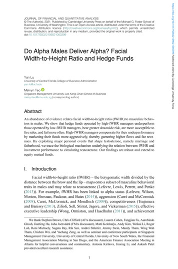
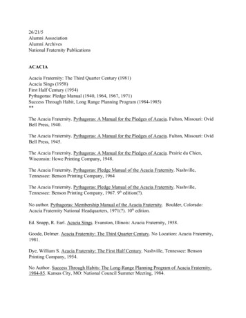
energy cost of this system is less than any currently existing mode of transport(Figure 1). The only system that comes close to matching the low energyrequirements of Hyperloop is the fully electric Tesla Model S.Figure 1. Energy cost per passenger for a journey between Los Angeles and San Francisco forvarious modes of transport.4. Hyperloop Transportation SystemHyperloop (Figure 2 and Figure 3) is a proposed transportation system fortraveling between Los Angeles, California, and San Francisco, California in 35minutes. The Hyperloop consists of several distinct components, including:1. Capsule:a. Sealed capsules carrying 28 passengers each that travel along theinterior of the tube depart on average every 2 minutes from LosAngeles or San Francisco (up to every 30 seconds during peakusage hours).Page 9
b. A larger system has also been sized that allows transport of 3 fullsize automobiles with passengers to travel in the capsule.c. The capsules are separated within the tube by approximately 23miles (37 km) on average during operation.d. The capsules are supported via air bearings that operate using acompressed air reservoir and aerodynamic lift.2. Tube:a. The tube is made of steel. Two tubes will be welded together in aside-by-side configuration to allow the capsules to travel bothdirections.b. Pylons are placed every 100 ft (30 m) to support the tube.c. Solar arrays will cover the top of the tubes in order to providepower to the system.3. Propulsion:a. Linear accelerators are constructed along the length of the tubeat various locations to accelerate the capsules.b. Rotors are located on the capsules to transfer momentum to thecapsules via the linear accelerators.4. Route:a. There will be a station at Los Angeles and San Francisco. Severalstations along the way will be possible with splits in the tube.b. The majority of the route will follow I-5 and the tube will beconstructed in the median.LosAngeles,CASanFrancisco,CAFigure 2. Hyperloop conceptual diagram.Page 10
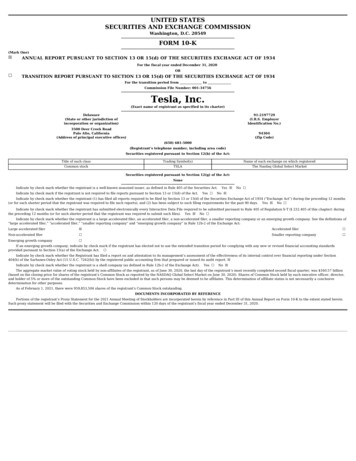
Figure 3. Hyperloop tube stretching from Los Angeles to San Francisco.In addition to these aspects of the Hyperloop, safety and cost will also beaddressed in this study.The Hyperloop is sized to allow expansion as the network becomes increasinglypopular. The capacity would be on average 840 passengers per hour which ismore than sufficient to transport all of the 6 million passengers travelingbetween Los Angeles and San Francisco areas per year. In addition, thisaccounts for 70% of those travelers to use the Hyperloop during rush hour. Thelower cost of traveling on Hyperloop is likely to result in increased demand, inwhich case the time between capsule departures could be significantlyshortened.4.1. CapsuleTwo versions of the Hyperloop capsules are being considered: a passenger onlyversion and a passenger plus vehicle version.Hyperloop Passenger CapsuleAssuming an average departure time of 2 minutes between capsules, aminimum of 28 passengers per capsule are required to meet 840 passengers perhour. It is possible to further increase the Hyperloop capacity by reducing thetime between departures. The current baseline requires up to 40 capsules inactivity during rush hour, 6 of which are at the terminals for loading andunloading of the passengers in approximately 5 minutes.Page 11
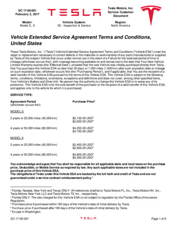
Hyperloop Passenger Plus Vehicle CapsuleThe passenger plus vehicle version of the Hyperloop will depart as often as thepassenger only version, but will accommodate 3 vehicles in addition to thepassengers. All subsystems discussed in the following sections are featured onboth capsules.For travel at high speeds, the greatest power requirement is normally toovercome air resistance. Aerodynamic drag increases with the square of speed,and thus the power requirement increases with the cube of speed. Forexample, to travel twice as fast a vehicle must overcome four times theaerodynamic resistance, and input eight times the power.Just as aircraft climb to high altitudes to travel through less dense air,Hyperloop encloses the capsules in a reduced pressure tube. The pressure of airin Hyperloop is about 1/6 the pressure of the atmosphere on Mars. This is anoperating pressure of 100 Pascals, which reduces the drag force of the air by1,000 times relative to sea level conditions and would be equivalent to flyingabove 150,000 feet altitude. A hard vacuum is avoided as vacuums areexpensive and difficult to maintain compared with low pressure solutions.Despite the low pressure, aerodynamic challenges must still be addressed.These include managing the formation of shock waves when the speed of thecapsule approaches the speed of sound, and the air resistance increasessharply. Close to the cities where more turns must be navigated, capsulestravel at a lower speed. This reduces the accelerations felt by the passengers,and also reduces power requirements for the capsule. The capsules travel at760 mph (1,220 kph, Mach 0.99 at 68 ºF or 20 ºC).The proposed capsule geometry houses several distinct systems to reside withinthe outer mold line (Figure 4).InletCompressorfanCompressormotorFirewall/sound bulkheadAir storageBatteriesSeating(2 x 14)SuspensionFigure 4. Hyperloop passenger capsule subsystem notional locations (not to scale).Page 12
4.1.1. GeometryIn order to optimize the capsule speed and performance, the frontal area hasbeen minimized for size while maintaining passenger comfort (Figure 5 andFigure 6).Figure 5. Hyperloop passenger transport capsule conceptual design sketch.Page 13
Figure 6. Hyperloop passenger transport capsule conceptual design rendering.The vehicle is streamlined to reduce drag and features a compressor at theleading face to ingest oncoming air for levitation and to a lesser extentpropulsion. Aerodynamic simulations have demonstrated the validity of this‘compressor within a tube’ concept (Figure 7).Figure 7. Streamlines for capsule traveling at high subsonic velocities inside Hyperloop.Page 14
Hyperloop Passenger CapsuleThe maximum width is 4.43 ft (1.35 m) and maximum height is 3.61 ft (1.10m). With rounded corners, this is equivalent to a 15 ft 2 (1.4 m2) frontal area,not including any propulsion or suspension components.The aerodynamic power requirements at 700 mph (1,130 kph) is around only134 hp (100 kW) with a drag force of only 72 lbf (320 N), or about the sameforce as the weight of one oversized checked bag at the airport. The doors oneach side will open in a gullwing (or possibly sliding) manner to allow easyaccess during loading and unloading. The luggage compartment will be at thefront or rear of the capsule.The overall structure weight is expected to be near 6,800 lb (3,100 kg)including the luggage compartments and door mechanism. The overall cost ofthe structure including manufacturing is targeted to be no more than 245,000.Hyperloop Passenger Plus Vehicle CapsuleThe passenger plus vehicle version of the Hyperloop capsule has an increasedfrontal area of 43 ft2 (4.0 m2), not including any propulsion or suspensioncomponents. This accounts for enough width to fit a vehicle as large as theTesla Model X.The aerodynamic power requirement at 700 mph (1,130 kph) is around only 382hp (285 kW) with a drag force of 205 lbf (910 N). The doors on each side willopen in a gullwing (or possibly sliding) manner to accommodate loading ofvehicles, passengers, or freight.The overall structure weight is expected to be near 7,700 lb (3,500 kg)including the luggage compartments and door mechanism. The overall cost ofthe structure including manufacturing is targeted to be no more than 275,000.4.1.2. InteriorThe interior of the capsule is specifically designed with passenger safety andcomfort in mind. The seats conform well to the body to maintain comfortduring the high speed accelerations experienced during travel. Beautifullandscape will be displayed in the cabin and each passenger will have accesstheir own personal entertainment system.Hyperloop Passenger CapsuleThe Hyperloop passenger capsule (Figure 8 and Figure 9) overall interior weightis expected to be near 5,500 lb (2,500 kg) including the seats, restraintsystems, interior and door panels, luggage compartments, and entertainmentPage 15
displays. The overall cost of the interior components is targeted to be no morethan 255,000.Figure 8. Hyperloop passenger capsule version with doors open at the station.Figure 9. Hyperloop passenger capsule version cutaway with passengers onboard.Page 16
Hyperloop Passenger Plus Vehicle CapsuleThe Hyperloop passenger plus vehicle capsule overall interior weight isexpected to be near 6,000 lb (2,700 kg) including the seats, restraint systems,interior and door panels, luggage compartments, and entertainment displays.The overall cost of the interior components is targeted to be no more than 185,000. Note this cost is lower than the passenger only capsule interior asvehicles do not require the same level of comfort as passengers.4.1.3. CompressorOne important feature of the capsule is the onboard compressor, which servestwo purposes. This system allows the capsule to traverse the relatively narrowtube without choking flow that travels between the capsule and the tube walls(resulting in a build-up of air mass in front of the capsule and increasing thedrag) by compressing air that is bypassed through the capsule. It also suppliesair to air bearings that support the weight of the capsule throughout thejourney.The air processing occurs as follows (Figure 10 and Figure 11) (note masscounting is tracked in Section 4.1.4):Hyperloop Passenger Capsule1. Tube air is compressed with a compression ratio of 20:1 via an axialcompressor.2. Up to 60% of this air is bypassed:a. The air travels via a narrow tube near bottom of the capsule tothe tail.b. A nozzle at the tail expands the flow generating thrust to mitigatesome of the small amounts of aerodynamic and bearing drag.3. Up to 0.44 lb/s (0.2 kg/s) of air is cooled and compressed an additional5.2:1 for the passenger version with additional cooling afterward.a. This air is stored in onboard composite overwrap pressure vessels.b. The stored air is eventually consumed by the air bearings tomaintain distance between the capsule and tube walls.4. An onboard water tank is used for cooling of the air.a. Water is pumped at 0.30 lb/s (0.14 kg/s) through two intercoolers(639 lb or 290 kg total mass of coolant).b. The steam is stored onboard until reaching the station.c. Water and steam tanks are changed automatically at each stop.5. The compressor is powered by a 436 hp (325 kW) onboard electricmotor:a. The motor has an estimated mass of 372 lb (169 kg), whichincludes power electronics.Page 17
b. An estimated 3,400 lb (1,500 kg) of batteries provides 45 minutesof onboard compressor power, which is more than sufficient forthe travel time with added reserve backup power.c. Onboard batteries are changed at each stop and charged at thestations.Axial compressorPin 276 kWAir Inp 99 PaT 292 K𝑚 0.49 kg/sAir Outp 2.1 kPaT 857 KNozzle expander𝑚 0.29 kg/sAir OutFthrust 170 NPthru
Page 2 hedging my statement slightly by saying "one of". The head of the California high speed rail project called me to complain that it wasn't the very slowest