Transcription
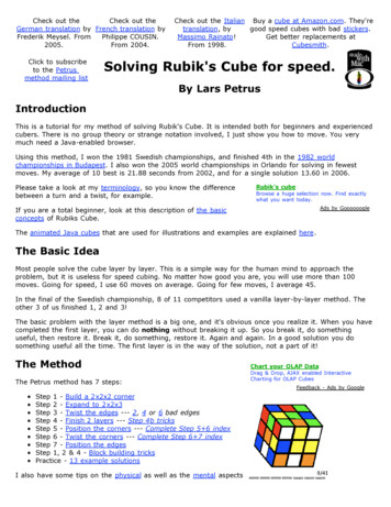
Stephen Tsung-Han Sher7555500940WRIT 340 - T TH 9:30AMProfessor TownsendApril 9, 2014Technical DescriptionThe New Durable Rubik’s CubeGeneral OverviewThe Rubik’s Cube is a 3-dimensional puzzle for all ages. The puzzle’s goal is to simplymatch each of the six sides of the cube with the same color by turning each face one afteranother. With approximately 43 quintillion1 possible arrangements, this simple toy offers acomplex puzzle experience. This technical paper will focus redesigning the original 3x3x3Rubik’s Cube to improve its durability and reduce its complexity through means of using PVCtiles and ball bearing movement.1exactly 43,252,003,274,489,856,000 unique permutationsPage 1 of 36
Table of Contents1 History .71.1 Preceding Designs .81.2 Rubik’s Design 81.3 Modern Design 92 Design 102.1 Dimensions . . 102.2 Materials . . 102.3 Color . . . 112.3.1 Color Composition .112.3.2 Color Arrangement . 132.4 Components .142.4.1 Core .142.4.2 Cubelets 152.4.2.1 Edge Cubelet 152.4.2.2 Corner Cubelet . 162.4.2.3 Center Cubelet . 172.4.3 Screws . 182.4.4 Springs . 182.5 Structure .192.5.1 Row Configurations . 192.5.1.1 Corner-Edge-Corner Configuration . 192.5.1.2 Edge-Center-Edge Configuration .20Page 2 of 36
2.5.1.3 Center-Core-Center Configuration 212.5.2 Layer Configuration . 222.5.2.1 Face Configuration . . 222.5.2.2 Center Configuration .232.5.3 Cube Configuration .242.6 Mechanics / Usage . 253 Redesign 263.1 Color Indication Method .263.2 Ball-bearing movement . 273.2.1 Ball Bearing . 283.2.2 Redesigned Components . 283.2.2.1 Redesigned Core . 293.2.2.2 Redesigned Center Cubelet . 303.3 Construction 313.4 Comparison . 323.4.1 Components . 333.4.2 Rotation Mechanism 343.4.3 Color Indication Method . 343.4.4 Layer Extension . . 353.4.5 Customizability 363.5 Improvements Summary .36Page 3 of 36
List of Figures1.1 Nickols’ puzzle design . 71.2-a . Rubik’s design . .81.2-b . Original Rubik’s Cube by Ideal Toy Corp 81.3 . Rubik’s Speed Cube .92.1 . Rubik’s Cube dimensions . 102.3.1-a . A blank Rubik’s Cube . 112.3.1-b . Outer dimensions of cubelets and colored adhesives . 122.3.1-c . A solved Rubik’s Cube . 122.3.2 . Color arrangement of the Rubik’s Cube . 132.4.1 . Schematic of a Rubik’s Cube core 142.4.2.1 . Schematic for an edge cubelet . 152.4.2.2 . Schematic for a corner cubelet .162.4.2.3 . Schematic for a center cubelet . 172.4.3 . Wood screw used in the Rubik’s Cube . 182.4.4 . Metal spring used in the Rubik’s Cube . 182.5.1.1 . Row type C-E-C configuration . 192.5.1.2 . Row type E-C-E configuration .202.5.1.3 . Row type C-C-C configuration . 212.5.2.1 . Face layer configuration 222.5.2.2 . Center layer configuration 232.5.3 . Combining layers to construct the cube 242.6 . Rotation methods . 25Page 4 of 36
3.1-a . Typical worn down Rubik’s Cube . 263.1-b . Application of PVC tiles using adhesives .273.2.1.1 . Dimensions of a ball bearing 283.2.1.2 . Schematic of redesigned core . 293.2.1.3 . Schematic of redesigned center cubelet 303.3 . Assembly of ball bearing with the new core and center cubelet .313.4.4-a . Extension of the center cubelet from the core . 343.4.4-b . Extension of entire face of the Rubik’s Cube . 34Page 5 of 36
List of Tables2.1 . RGB values of Rubik’s Cube colors . 133.1 . Comparison between original and redesigned Rubik’s Cube . 323.2 . Table of components in both the original and redesigned Rubik’s Cube . 33Page 6 of 36
1HistorySince the invention of the modern Rubik’s Cube in 1974 by Ernö Rubik, this toy has soldover 350 million units, not including the sales of the many variations and imitations of the cube.From the first prototype to the modern Speed Cube, there has only been two major designchanges in the Rubik’s Cube.1.1Preceding Design (1970 - 1972)Larry Nichols invented the original concept of the puzzle in 1970. His invention was a2x2x2 combinational puzzle held together by magnets (figure 1.1). Nichols patented hisinvention on 1972, and called it the “Pattern Forming Puzzle and Method with Pieces Rotatablein Groups”2. Nichols’ puzzle design was unsuccessful in sales.Figure 1.1: Nichols’ puzzle patent2Patent publication number [US 3655201 A]Page 7 of 36
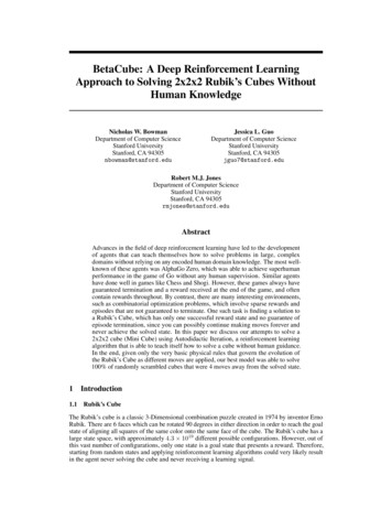
1.2Rubik’s Design (1974 - today)Ernö Rubik, a Hungarian sculptor and architecture professor, invented the design of themodern Rubik’s Cube, originally called the Magic Cube (figure 1.2-a) 3, in 1974.Figure 1.2-a: Rubik’s original design (replica by Tony Fisher)In 1975 Rubik redesigned his cube to consist of plastic interlocking pieces, the samedesigned used today and the design discussed later in this paper. This design was far moredurable than Nichols’ magnetic design and became a success. In 1980, Rubik licensed hisinvention to the Ideal Toy Corporation (figure 1.2-b) 4 and his toy made its international debut inthe same year. He also won the “German Game of the Year” award for the “Best Puzzle” in 1980.Figure 1.2-b: Original Rubik’s Cube by Ideal Toy Corp.3Image source: Tony Fisher4Image source: John P. A. CarterPage 8 of 36
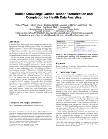
1.3Modern Design (2013 - today)Rubik’s original design in 1975 was the only official Rubik’s cube design until 2013. In2013 the Rubik’s Brand Ltd released the Rubik’s Speed Cube. Rubik’s Speed Cube consists of aspherical core (figure 1.3.1)5, allowing smoother turning of the faces and reduced chances ofdisassembly when turning the faces at high speeds. Albeit the Speed Cube having a better design,the original Rubik’s Cube remains a widely popular option for the casual customer.Figure 1.3: Partially disassembled Rubik’s Speed Cube5Image source: Rubik’s Brand LtdPage 9 of 36
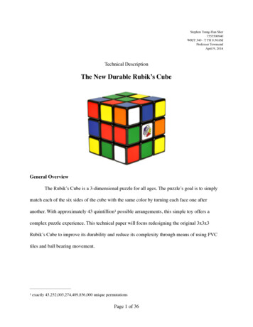
2DesignThe Rubik’s Cube is a toy small enough to be carried comfortably in one hand; it is alsobig enough for the user to be able to manipulate the toy with both hands with ease. Each of thesix faces of the cube is uniquely colored.2.1DimensionsThe cube measures 5.70 centimeters on each edge. Each face of the cube is partitionedinto nine smaller even cubes, called cubelets, in a 3-by-3 arrangement, with each cubelet’s outerfacing edges measuring 1.90 centimeters (figure 2.1).Figure 2.1: Rubik’s Cube dimensions2.2MaterialsThe entire cube is composed of polymer-based plastic: either low density polyethylene(LDPE) or Polyvinyl-chloride (PVC). The only exception is the six metal screws and springsholding the central core of the cube together. The color-indication method on the cube is doneusing colored plastic adhesives composed of polyethylene terephthalate (PET).Page 10 of 36
2.3ColorThe standard Rubik’s Cube follows a set color composition and arrangement. Any otherdiffering color composition or arrangements from what is described in this section are notconsidered to be the standard Rubik’s Cube.2.3.1Color CompositionThe main cube is black in color except the color-indication components and the centralcore that is not visible at all times (figure 2.3.1-a)6 when the cube is fully assembled.Figure 2.3.1-a: A blank Rubik’s Cube6Image source: of Rubik’s Brand Ltd.Page 11 of 36
Each outer face of the cubelets has a specific color assigned. Color-indication adhesivecomponents are squares measuring 1.70 centimeters, leaving a visible black border around eachcubelet (figure 2.3.1-b).Each of the six faces of the Rubik’s Cube are indicated by unique solid colors: White,yellow, red, blue, orange, and green.1.70 cm1.90 cmFigure 2.3.1-b: Outer dimensions of a cubelet and colored adhesiveAt the toy’s solved state, the same color is arranged on each face of the cube (figure2.3.1-c)7, ergo each unique color is assigned to nine cubelet faces.Figure 2.3.1-c: A solved Rubik’s Cube7Image source: of Rubik’s Brand Ltd.Page 12 of 36
2.3.2Color ArrangementThe standard color-arrangement is as follows: Red is opposite from blue, orange isopposite from green, and white is opposite from yellow. The red, white, and blue color faces areadjacent from one another and are arranged in a clockwise manner (figure 2.3.2).Figure 2.3.2: Color arrangement of the Rubik’s CubeThe following table is the RGB values of the hues of the six colors used on the officialRubik’s Cube.RGB e 2.1: RGB values of the Rubik’s Cube colorsPage 13 of 36
2.4ComponentsThe entire cube is composed of one core and twenty-six cubelets, all held together by sixmetal screws, six springs and all the cubelets interlocking with each other.2.4.1CoreThe center of the cube is a plastic axial core constructed as three cylindrical tubesintersecting one another at 90º from one another (figure 2.4.1). The length of each axial cylinderis 1.90 cm; the outer diameter is 0.76cm and the inner diameter at 0.25cm. The core uses sixmetal screws, one for each face, to hold the core and central cubelets together; the metal screwsare installed in the cylindrical tubes of each axle.Figure 2.4.1: Schematic of Rubik’s Cube corePage 14 of 36
2.4.2CubeletsThe twenty-six cubelets can be categorized into three different types: edge, corner, andcenter. The Rubik’s Cube is composed of twelve edge cubelets, eight corner cubelets, and sixcenter cubelets. The colored adhesives are applied to the outward facing sides of the cubelet.2.4.2.1 Edge Cubelet (figure 2.4.2.1)The edge cubelet has two outward facing sides. There is a rectangular prism protrudingfrom the inner edge of the cubelet, serving as the interlocking mechanism for the cube. The innercorner of the two faces adjacent to both colored faces are truncated in order for circular rotationwith the other cubelets. The cubelet and the protrusion are hollowed out in order to reduceweight without significant compromisation to structural integrity.Figure 2.4.2.1: Schematic for edge cubeletPage 15 of 36
2.4.2.2 Corner Cubelet (figure 2.4.2.2)The corner cubelet has three outward facing sides. There is a smaller cube with threerounded faces protruding from the inner corner of the cubelet, serving as the interlockingmechanism for the cube. The rounded truncation of the protruding cube allows for circularrotation with the other cubelets. The corner cubelet is hollow on the inside to reduce weight butmaintaining structural integrity.Figure 2.4.2.2: Schematic for corner cubeletPage 16 of 36
2.4.2.3 Center Cubelet (figure 2.4.2.3)The center cubelet has one outward facing side. The face directly opposite from thecolored face has a cylindrical protrusion, hollowed at the center to allow a screw for attachmentto the core. The four inner edges of the cubelet are rounded outwards in order to allow circularrotation with the other cubelets. The outward face is a square cap that snaps onto the cubelet toconceal the screw. Beneath the cap reveals the interior chamber of the cubelet for the installmentand access to the spring and screw.Figure 2.4.2.3: Schematic for center cubeletPage 17 of 36
2.4.3ScrewsSix wood screws (figure 2.4.3) are used to hold the six center cubelets with the core. Thesmooth shank of the wood screw allows smooth sliding of the screw against the inner surfaces ofthe cubelet with each rotation of the cube, minimizing the damage done to the plastic surfacesthrough prolonged usage.Figure 2.4.3: Wood screw2.4.4 SpringsSix springs (figure 2.4.4) will sit between the wood screw and the inner chamber of thecenter cubelet. The spring will provide constant tension pulling the center cubelet against thecore, ensuring the entire cube being held together as one single unit.Figure 2.4.4: Metal springPage 18 of 36
2.5StructureEach of the cubelets are interconnected to one another by the interlocking design of theprotrusion of the edge and corner cubelet. The center cubelet serves as an axial pivot point.2.5.1Row ConfigurationEach row is either configured as corner-edge-corner, edge-center-edge, or center-core-center. These row configurations will then be combined to form a layer configuration.2.5.1.1 Corner-Edge-Corner Configuration (C-E-C)The edge cubelet rests between two corner cubelets. The protrusions of the two cornercubelets will be facing inwards towards the edge cubelet (figure 2.5.1.1). The sides of the cornercubelet’s protrusions will rest against the inner edge of the edge cubelet, holding the cornercubelets in place. The top of the protrusions of all three cubelets will align flush with each other.The rounded edges of all three cubelet’s protrusions will align to form part of a circle (denotedby dotted red line in figure 2.5.1.1).Figure 2.5.1.1: Row type C-E-C configurationPage 19 of 36
2.5.1.2 Edge-Center-Edge Configuration (E-C-E)The center cubelet rests between two edge cubelets. The protrusions of the two edgecubelets will be facing inward towards the center cubelet (figure 2.5.1.2). The bottom of the twoedge cubelet’s protrusions will rest above the inner edge of the center cubelet, holding the edgecubelets in place. The top of the center cubelet’s protrusion will rest below the top of the edgecubelet’s protrusion; this recess will make room of the core’s axial cylinders to connect with thecenter cubelets. The rounded edges of the cubelets will align to form a part of a circle (denotedby dotted red line in figure 2.5.1.2).Figure 2.5.1.2: Row type E-C-E configurationPage 20 of 36
2.5.1.3 Center-Core-Center Configuration (C-C-C)The cube core rests between two center cubelets. The two center cubelets are connectedto the core by means of the wood screw. The wood screw will be threaded through the spring,inserted, and fastened through the center cubelets. The cap will then be placed onto the centercubelet to conceal the spring and screw (figure 2.5.1.2).Figure 2.5.1.3: Row type C-C-C configurationPage 21 of 36
2.5.2Layer ConfigurationCombining the three row configurations will result in the layer configurations. There aretwo layer configurations: face layer and center layer. These layer configurations will then becombined to form the entire cube.2.5.2.1 Face ConfigurationThe face layer configuration is composed of two C-E-C rows and one E-C-E rowconfiguration. The two C-E-C rows will sandwich the single E-C-E rows (figure 2.4.2.1). Thecorner cubelet’s protrusions will be resting against the two adjacent edge cubelet’s inner side andadjacent the single center cubelet’s inner corner. The edge cubelet’s protrusions will only beresting against the center cubelet’s inner edge. The center cubelet’s inner edges will be holdingall other eight cubelet in place, interlocking each cubelet with one another. The rounded edges ofthe protrusions of the cubelets will form a circle, serving as the rotational track for each layer torotate against the other layers (denoted by dotted red circle in figure 2.5.2.1).Figure 2.5.2.1: Face layer configurationPage 22 of 36
2.5.2.2 Center ConfigurationThe center layer is composed of two E-C-E rows and one C-C-C row. The two E-C-Erows will sandwich the one C-C-C row (figure 2.5.2.2). The protrusion of the edge cubelet willrest against the inner edges of the center cubelets, holding the edge cubelet in place. The corewill be holding each of the four center cubelets together using the springs and screws. Therounded inner edges of all eight cubelets will form a circle, serving as the rotational track for thislayer to rotate freely against the other layers (denoted by dotted red circle in figure 2.5.2.2).Figure 2.5.2.2: Center layer configurationPage 23 of 36
2.5.3Cube ConfigurationThe twenty-six cubelets and the core can be combined to gather to form two face layersand one center layer. By combining the two face layers with the single center layer in a sandwichfashion (figure 2.5.3), the entire Rubik’s Cube will be assembled and completed.Each protrusion of the edge and corner cubelets sits against one another and against thecenter cubelet, and each center cubelet is held together with the core; this interconnection of thecubelets interlocks all twenty-six cubelets together.In this completed configuration, there will be six circular tracks formed by the roundedinner edges of the cubelets. Each of these six circular tracks allows for each of the six layers torotate: the core mechanic of the Rubik’s Cube’s design.Figure 2.5.3: Combining layers to construct cubePage 24 of 36
2.6Mechanics / UsageThe rearrangement of colors is achieved through rotating each face of the cube 90degrees at a time. Each face can be rotated clockwise or counterclockwise (figure 2.5.4). Witheach of the six faces having two degrees of movement, this totals to twelve possible rotationoptions on the cube.Figure 2.5.4: Rotation methodsWith each 90 degree rotation, the corner and edge cubelets aligns with the edge andcenter cubelets of the adjacent face’s cubelets, allowing for subsequent rotations to occur in anyof the twelve choices.Each rotation will displace all four corner and all four edge cubelets to the adjacent facecorresponding to the direction of the rotation, transposing the arraignment of the colors. Only thecenter cubelets never displace due to the rotations pivoting around the center cubelets. Thereforethe color of the center cubelet on each of the six faces indicate the color of the entire face whenthe puzzle is completed in its final color arrangement.Page 25 of 36
3RedesignThe traditional Rubik’s Cube’s design has been used for over forty years. However thereis a flaw in the design that has never been fixed: durability. The two components of the Rubik’sCube that lacks durability are the color indication stickers and the rotational mechanism. Theredesign will address both flaws.3.1Color Indication MethodThe traditional method of using colored stickers on the Rubik’s Cube has a major flaw inits durability. The corners of the stickers peel easily and is easily subject to wear (figure 3.1-a) 8.Even the professional grade stickers for professional speed-cubers has a lifespan of750,000 rubs. This results in either constant replacement of stickers or of the entire cube itself.Figure 3.1-a: Typical worn down Rubik’s Cube8Image source: Helen W. ChangPage 26 of 36
In order to greatly improve the durability and lifespan of the color-indication method,PVC colored tiles can be used instead. This can be easily implemented by applying a strongadhesive or epoxy to the back side of the tile and binding the tile to the face of the cubelets(figure 3.1-b).Plastic colored tiles eliminate the problem of the stickers wearing down. Furthermore, byusing a strong adhesive to attach the tiles to the cubelet’s faces, the tiles eliminate the issues ofpeeling, tearing, or being inadvertently removed.Colored PVC tileFigure 3.1-b: Application of colored PVC tiles using adhesivesPage 27 of 36
3.2Ball Bearing MovementInstead of using a spring and wood screw to connect the core to the center cubelets, usinga ball bearing can smoothen rotations, reduce the number of components, and reduce assemblysteps.3.2.1Ball BearingThe type of ball bearing used will be a deep-groove radial ball bearing. This componentwill be constructed from heavy-duty steel to ensure maximum durability. The ball bearing will beof a cylindrical shape, with the outer diameter at 0.50 cm, the inner diameter at 0.25 cm, and theheight at 0.50 cm. Due to the small dimensions, the additional six ball bearings added to theRubik’s cube will not increase the overall weight by any significant amount.Figure 3.2.1.1: Schematic of ball bearing3.2.2Redesigned ComponentsThis redesigned Rubik’s Cube using ball bearing movement will consist the redesigningof two existing components, the center cubelet and the core. As a result, this redesign willeliminate three components in the original design: the wood screw, spring, and center cubeletcap.Page 28 of 36
3.2.2.1 Redesigned CoreTo install the ball bearing onto the core, the core will now have an additional cylindricalprotrusion from each of the six axial ends (figure 3.2.1.2). Each protrusion will measure 0.50 cmin length and 0.25 cm in diameter. Since wood screws are no longer used, it is no longernecessary to mill cylindrical channels down the middle of the axles. The core will still becomposed of LDPE or PVC, ensuring the structural integrity of the protrusions, thus theprotrusions will not likely be subject to breaking or fracturing.Figure 3.2.1.2: Schematic of redesigned corePage 29 of 36
3.2.2.2 Redesigned Center CubeletThe cylindrical axle will have a cylindrical recess in order to house the ball bearingcomponent. This recess will be milled a depth of 0.50 cm and a diameter of 0.50 cm. Due to theelimination of the wood screw and spring, the center cubelet no longer needs a cap nor interiorchamber.Figure 3.2.1.3: Schematic of redesigned center cubeletPage 30 of 36
3.3ConstructionAssembly of the the ball bearing occurs in two steps. The ball bearing is first insertedonto the protrusion on the core’s axles, the center cubelet will then be inserted onto the ballbearing afterwards (figure 3.3). The resulting construction will have the ball bearing acting as arotational interface between the core and the center cubelet, housed onto the core’s protrusionsand inside the center cubelet’s recess.An epoxy or other binding agent will be used on the metal-polymer interface in theattachment of the ball bearing, eliminating the possibility of deconstruction of the ball bearinginterface.This construction replaces all core-center-cubelet attachment steps. All other proceduresin the construction of the cube remains the same.Apply epoxy or binding agent hereFigure 3.3: Assembly of ball bearing with the new core and center cubeletPage 31 of 36
3.4ComparisonThe following table summarizes the features and specifications between the originalRubik’s Cube and the redesigned Rubik’s Cube. Detailed discussion on each feature andspecification will follow n mechanismSpring and wood screwSteel deep groove radial ball bearingColor indication methodPET stickersPVC colored tilesLayer ictedTable 3.1: Comparison between original and redesigned Rubik’s CubePage 32 of 36
3.4.1ComponentsThe ball bearing component replaces the wood screw and spring components in theoriginal cube; in addition, using the ball bearing eliminates the need to access the interiorchamber of the center cubelet, therefore eliminating the need for the center cubelet cap. Bothdesigns still requires 54 color indication components (9 components for each of the 6 colors), 26cubelets and a single core. The redesigned cube requires 12 less components than the original.Furthermore, the reduced components and simplified design reduces the number of assemblysteps required, quickening the production of each unit. The following table lists the componentsin both the original and redesigned Rubik’s Cube.Original Rubik’s CubeRedesigned Rubik’s CubeSticker (red) x 9PVC Tile (red) x 9Sticker (blue) x 9PVC Tile (blue) x 9Sticker (white) x 9PVC Tile (white) x 9Sticker (orange) x 9PVC Tile (orange) x 9Sticker (green) x 9PVC Tile (green) x 9Sticker (Yellow x 9PVC Tile (Yellow x 9Core x 1Core x 1Center cubelet x 6Center cubelet x 6Edge cubelet x 12Edge cubelet x 12Corner cubelet x 8Corner cubelet x 8Center cubelet cap x 6Ball bearing x6Wood screws x 6Springs x 6Total99 componentsTotal87 componentsTable 3.2: Table of components used in both original and redesigned Rubik’s CubePage 33 of 36
3.4.2Rotation MechanismThe rotation mechanism of the original cube comprises of a spring and wood screwholding the core and center cubelets together. As a result each rotation is resisted by the frictionalforces between the core and center cubelets. Using the ball bearing mechanism eliminates thisfriction, resulting in significantly smoother and more consistent rotations. The ball bearing iscomposed of steel, however due to the small dimensions of the ball bearing, this will not add anysignificant weight to the final product.3.4.3Color Indication MethodThe redesigned cube uses PVC colored tiles. PVC tiles is not subject to wear, loss ofcolor when rubbed, nor will it peel after extensive use. However, these tiles will result in anincrease in storage space, albeit not a significant amount. Taking into account off all the reducednumber of components, the net storage space for all the components of the redesigned cube willstill be less than that of the original Rubik’s Cube.Page 34 of 36
3.4.4Layer ExtensionLayer extension refers to the degree in which the center cubelet can extend from the core.In the original model, due to the spring mechanism, the center cubelet can be extended outwards(figure 3.4.4-a), ergo extending the entire face layer outwards (denoted by red line in figure3.4.4-b) to a small extent. This allows for greater maneuverability and flexibility in themanipulation of the cube. The newer design binds the ball bearing to both the core and cubelet,no longer allowing this extension to happen. However the average user will not concerned withoptimizing the performance of the cube, ergo not significantly impacting the target audience.Figure 3.4.4-a: Extension of the center cubelet from the coreFigure 3.4.4-b: Extension of entire face of the Rubik’s CubePage 35 of 36
3.4.5CustomizabilityThe original design of the Rubik’s Cube allows its users to adjust the tightness of thescrew and the stiffness of the spring to suit the cube’s performance for each individual user. Inthe redesigned version, there is no such area for customizability. However, the average user ofthe Rubik’s Cube will not consider customizing their Rubik’s Cube; customization is onlynecessary for those who want to pursue speed-cubing and solve the Rubik’s Cube competitively.The consumers who want to customize their cube and pursue speed-cubing will beinvesting in the Rubik’s Speed Cube instead of the classic Rubik’s Cube; therefore, thisrestriction in the redesigned cube will not significantly impact the intended audience.3.4.6Improvements SummaryFrom the consumer’s perspective, the redesigned Rubik’s Cube provides more durablecolor-indication components, as well as smoother and more consistent rotation movement. Thereduced customizability and flexibility in complex maneuvers are unrelated to the target audienceof this product.From the supplier’s perspective, the redesigned Rubik’s Cube reduces the number ofindividual components in cube as well as reduced assembly procedures, allowing faster andcheaper production.Page 36 of 36
1.2 Rubik's Design (1974 - today) Ernö Rubik, a Hungarian sculptor and architecture professor, invented the design of the modern Rubik's Cube, originally called the Magic Cube (figure 1.2-a)3, in 1974. In 1975 Rubik redesigned his cube to consist of plastic interlocking pieces, the same