Transcription
Manual of Water Supply PracticesM28Rehabilitationof Water MainsThird EditionIdeal crop marksCopyright 2014 American Water Works Association. All Rights Reserved.
Ideal crop marksContentsList of Figures, vList of Tables, viiForeword, ixAcknowledgments, xiChapter 1Pipeline Renewal Methods. . . . . . . . . . . . . . . . . . . . . . . . . . . . . . . . . . . . . . . . 1Distribution System Water Quality Improvement, 2Hydraulic Improvement, 3Structural Improvement, 5Water Main Condition Evaluation, 6Prioritization, 6Costs and Benefits, 7Rehabilitation Solutions, 7Selection of Rehabilitation Solutions, 7Reference, 10Chapter 2Preconstruction Activities. . . . . . . . . . . . . . . . . . . . . . . . . . . . . . . . . . . . . . . . 11Advance Planning Considerations, 11Preparation of Plans and Specifications, 12Water Main Rehabilitation Contracts, 12Chapter 3Maintaining Service. . . . . . . . . . . . . . . . . . . . . . . . . . . . . . . . . . . . . . . . . . . . . 15Bypass Piping, 15Community Relations, 18Summary, 18References, 18Chapter 4Pipeline Cleaning Methods. . . . . . . . . . . . . . . . . . . . . . . . . . . . . . . . . . . . . . 19Flushing, 19Air Scouring, 20Mechanical Cleaning Techniques, 20Fluid-Propelled Cleaning Devices, 21Metal Scrapers, 25Cleaning by Power Boring, 29Ball Cleaning, 32References, 32Chapter 5Cement–Mortar Lining . . . . . . . . . . . . . . . . . . . . . . . . . . . . . . . . . . . . . . . . . . 33Cement–Mortar Lining, 33Reference, 37Chapter 6Spray-On Polymer Lining. . . . . . . . . . . . . . . . . . . . . . . . . . . . . . . . . . . . . . . . 39Definition of Polyurea Materials, 40Reference, 46AWWA Manual M28iii Association. All Rights Reserved.Copyright 2014 American Water Works
Chapter 7Cured-In-Place Pipe Lining Techniques . . . . . . . . . . . . . . . . . . . . . . . . . . . 47Classification of Systems, 47Reference, 51Chapter 8Sliplining. . . . . . . . . . . . . . . . . . . . . . . . . . . . . . . . . . . . . . . . . . . . . . . . . . . . . . 53Sliplining and Modified Sliplining, 53Sliplining, 53Modified Sliplining Techniques, 58Symmetrical Reduction Systems, 60Folded and Formed Systems, 62Expanded PVC Systems, 64Liner Termination Fittings, 64References, 75Chapter 9Internal Joint Seals. . . . . . . . . . . . . . . . . . . . . . . . . . . . . . . . . . . . . . . . . . . . . . 69Fitting Procedure for Internal Joint Seals, 70References, 10Chapter 10Pipe Bursting. . . . . . . . . . . . . . . . . . . . . . . . . . . . . . . . . . . . . . . . . . . . . . . . . . . 77History, 77Process Overview, 77Water Main Pipelines Replaced By Pipe Bursting, 81Differences Between Pipe Bursting, 83Project Execution Recommendations, 85Replacement Pipe Materials, 86Conclusions, 87References, 87Chapter 11Reinstatement of Service Laterals. . . . . . . . . . . . . . . . . . . . . . . . . . . . . . . . . 89Lateral Reinstatement for Spray-Applied Linings, 89Lateral Reinstatement for Nonspray-Applied Linings, 90Pavement Coring and Grouting, 94Pipeline Robots for Lateral Reinstatement, 94Reference, 95Chapter 12Cathodic Protection Retrofits. . . . . . . . . . . . . . . . . . . . . . . . . . . . . . . . . . . . . 97Predesign Field Testing, 97System Design, 99Testing and Maintenance, 100Reference, 100Chapter 13Program Management. . . . . . . . . . . . . . . . . . . . . . . . . . . . . . . . . . . . . . . . . . 101Customer/Community Relations, 101Project Notifications, 102Communication Needs, 104Responding to Problems, 105Contract Documents, 106Post-Construction Activities, 107Appendix AStructural Lining Design Issues. . . . . . . . . . . . . . . . . . . . . . . . . . . . . . . . . 111Index, 115List of AWWA Manuals, 119ivCopyright 2014 American Water WorksAssociation. All Rights Reserved.AWWA Manual M28
AWWA MANUALM28Chapter1Pipeline RenewalMethodsPipeline renewal is typically accomplished by one of two approaches: rehabilitation oropen-trench construction, although other trenchless methods are also used. Trenchlesstechnology is a type of subsurface construction work that requires little or no surfaceexcavation and no continuous trenches. This chapter provides guidance in selectingbetween rehabilitation and open-trench construction and in determining whichrehabilitation method is most appropriate for meeting goals.The renewal of water mains is performed for three primary reasons:1. Water Quality Improvement: to improve the quality of the water received by theconsumer2. Hydraulic Improvement: to increase the hydraulic capacity of the pipeline3. Structural Improvement: to reduce leakage, decrease repair frequencies, lessenrisk of property damage, and improve reliability.Compared with conventional open-trench replacement, pipeline rehabilitation methods are often less expensive and less disruptive to the community; however, rehabilitationis not appropriate for all situations.As described in other chapters in this manual, many different water mainrehabilitation techniques exist, offering a variety of benefits. The best choice of method foreach situation will depend on several factors, including: (1) the reason for the rehabilitation,(2) comparative costs, (3) site conditions, and (4) expected life-cycle performance.This chapter provides guidance in selecting a pipeline renewal method, including aseries of decision trees that can be used to help determine which types of methods shouldbe considered.1Copyright 2014 American Water Works Association. All Rights Reserved.
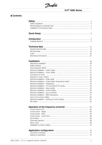
2 REHABILITATION OF WATER MAINSDISTRIBUTION SYSTEM WATER QUALITY IMPROVEMENTWater main rehabilitation is frequently performed to mitigate water quality deteriorationthat occurs within the distribution system. The goal is to improve water quality at thepoint of use. The improvements can be very dramatic, particularly when the existing mainis unlined cast iron.In most cases, the water quality benefits achieved by the various pipeline rehabilitation methods are fairly equal. This assumes that the materials being employed are certified in accordance with NSF/ANSI Standard 61, and industry accepted standards areemployed. It also assumes that the water is not particularly soft. When the water is soft,problems with high pH can occur if cement–mortar lining is used.The quality of treated drinking water can vary considerably, both from system tosystem and within a system, as a result of deterioration after it leaves the treatment plantand comes in contact with the interior of distribution system piping. Over time, changesin water chemistry can cause problems throughout the distribution system, ultimatelyaffecting the quality of the water delivered to the end user. The deterioration of waterquality that occurs within the water distribution system is often signaled by customercomplaints regarding the clarity, color, taste, and odor of the water. Although the watermay be safe to drink, it may be aesthetically unpleasant due to sediment that has beenstirred up or by biological processes that can thrive in highly scaled pipelines and impartan odor to the water. However, the concern is not always simply about aesthetics. Waterstagnation and chlorine depletion occur in highly scaled pipelines, resulting in greaterrisk of coliform regrowth. The majority of these problems fall into three categories:sedimentation, scaling, and biofilm formation.SedimentationSedimentation is the process whereby solids settle out of water moving at low velocity ina main, reducing interior cross section and capacity and becoming a potential source ofcustomer complaints about water quality. Source water pipelines or pipelines carryingunfiltered or improperly treated water can be subject to deposits of sand, silt, or organicmaterials. In pipelines receiving well water, particulates from oxidation of iron or manganese are also common, if the water is not filtered. In extreme cases, sedimentation can alsocontribute to hydraulic problems, particularly at low points in the pipe. The most commonsource of sediment is the internal corrosion of the pipeline itself.In smooth-walled pipelines, sediment generally moves through the system at moderate flow velocities and does not accumulate. However, where the pipeline is heavily scaled,sediment settles into the recesses of the scale and builds up over time. This sediment canthen be stirred up when the flow velocity increases (e.g., a fire hydrant is opened) or thedirection of flow reverses. The result can be severely discolored water as a large volume ofsediment becomes suspended and is delivered to the customer’s tap.Scaling or TuberculationScaling is the formation of hard deposits on the inside wall of the pipe. These depositsare frequently the by-product of pipe corrosion, wherein iron combines with calcium andother minerals within the water to form tubercles. The process, often called tuberculation,is assisted by bacteria within the scale that feed on iron leached from the pipe. Althoughscaling is most pronounced in cast-iron pipes, it is also commonly found in unlined steelpipes, copper pipes, concrete, and asbestos–cement pipes. Figure 1-1 shows a fairly typicaltuberculated cast-iron pipeline.Copyright 2014 American Water Works Association. All Rights Reserved.AWWA Manual M28
Pipeline Renewal Methods 3Figure 1-1Pipe with tuberculation caused by corrosionBefore the 1960s, many iron pipes were installed without effective, long-lastinglinings to protect the interior surfaces. These pipes often experience internal corrosion anddevelop tubercular scales. This scaling restricts the flow and creates areas where sedimentis deposited, and chlorine depletion occurs.Water discoloration complaints can occur when these sediment deposits are stirredup as previously described; however, discoloration can also occur if the corrosion activity within the pipeline is particularly high. If the scales are removed and a lining is notsubsequently installed, exposure of the underlying iron or steel pipeline often results inincreased corrosion activity and more frequent complaints about water discoloration.Such corrosion activity can be controlled to some extent through water chemistry (corrosion inhibitors), but cleaning of pipelines without lining is generally not recommended.Biofilm FormationBiofilms can develop within pipe made from any type of material; however, biofilms aremost common within highly scaled cast-iron pipe, where sediments and recesses allowiron-reducing bacteria to thrive in the absence of effective disinfectant. As the pipelinescorrode and tubercles develop, the hospitality of the environment for biofilm increases.The greater the roughness of the pipe surface, the harder it is for an effective disinfectantresidual to be maintained near the pipe surface. The reduction of the iron leached from thepipe also provides the energy source for the bacteria.Biofilms also form readily in raw water systems or portions of the finished watersystem where water is high in iron or manganese or other nutrients. Such biofilms takethe form of slimes, i.e., soft and filamentous. Even where scales do not form, these biofilmscan severely affect water clarity and produce taste-and-odor problems. They can alsosignificantly diminish hydraulic capacity.HYDRAULIC IMPROVEMENTIncreasing roughness and the buildup of scale or slime inside water distribution pipingcan greatly reduce the hydraulic performance of the system. This can significantly impactAWWA Manual M28Copyright 2014 American Water Works Association. All Rights Reserved.
4 REHABILITATION OF WATER MAINSthe ability to deliver adequate fire flows and can also affect pressures and flows availableto customers.Hydraulic engineers are able to calculate head losses and flow in pipes using theempirically derived Hazen–Williams formula, which relates flow to the physical properties of the pipe and pressure changes due to friction; however, the Hazen–Williamsequation cannot be applied to all fluids in all conditions. It is only valid for ambient temperatures (40 F to 75 F [4.4 C to 23.8 C]) and at turbulent flow (Reynolds numbers above105). For liquids outside these parameters, the Darcy–Weisbach formula is more reliable forfrictional head loss calculations at steady-state flow. In more complicated instances, computer models based on Hardy Cross are more accurate. For the discussion in this manual,the Hazen–Williams equation is:where:V k R C S V kCR0.63 S0.54(Eq. 1-1)velocity, ft/sec (m/sec)conversion factorhydraulic radius, ft (m), which is the cross-sectionalarea of the pipe divided by the wetted perimeterHazen–Williams roughness coefficientslope of the hydraulic grade line, ft/ft (m/m)C is a measure of the roughness of the interior of the pipe. Expressed in terms of C, theformula can be stated several ways. Once such way is stated as:where:CQDHLC 2,466QD–2.63 H0.54 L0.54 (Eq. 1-2)Hazen–Williams roughness coefficientquantity of flow in a pressure conduit, mgd (m3/d)nominal diameter of the pipe, in. (mm)head loss, ft (m) of waterlength of pipe, ft (m)The Hazen–Williams C factor, and hence the flow in a pipeline, depends on the typeof pipe and its interior condition (see Table 1-1). For a given velocity, increased internalsurface roughness (changing laminar to turbulent flow) leads to greater pressure loss. Bymeasuring pipe flows and pressure changes between two points along a pipeline, operators can calculate Hazen–Williams C factors and determine the degree the pipeline hasbecome roughened and constricted. These data help in making informed decisions aboutwhich process to employ to restore hydraulic efficiency. Collecting data for the Hazen–Williams C factor after employing a cleaning or pipe rehabilitation process is also a usefulway to gauge the impact of the system improvements.Table 1-1Hazen–Williams roughness coefficientConditionNew pipeC130–140Fair to normal (interior clean)100Significant reduction in pipe capacity70Severe problem—interior cross section greatly reduced30–50Copyright 2014 American Water Works Association. All Rights Reserved.AWWA Manual M28
Pipeline Renewal Methods 5Pipeline rehabilitation very frequently results in significant improvement of systemhydraulics, particularly where a cast-iron main is choked with tuberculation. Not onlyis a smoother pipe surface achieved, but at times, the effective flow cross section can beincreased significantly.Because the various methods use different materials and result in different internal diameters, the various methods achieve different degrees of hydraulic improvement.Table 1-2 provides a general comparison of the hydraulic improvements that the variousrehabilitation methods can provide.Moderate hydraulic improvement can also be achieved by some of the pipelinecleaning methods.STRUCTURAL IMPROVEMENTThe structural performance of water mains deteriorates over time due to several causes.Cast-iron, ductile-iron, and steel piping are subject to internal and external corrosion,resulting in pitting and wall thinning, which can lead to leaks and eventual burst failures. Cement-based pipes such as asbestos–cement and concrete pipe may also be subject to deterioration due to corrosion of the cement matrix and/or steel reinforcement. Inaddition, all types of pipe, including plastic, may be subject to joint failure between pipelengths and hence excessive leakage, which can in turn lead to washout of bedding andsubsequent structural failure.Such structural and leakage failures can have direct consequences such as highrepair costs, water quality problems, service interruptions, and loss of treated water. Theymay also have indirect consequences in terms of the economic damage associated withpipe bursts and the public relations damage to the service provider.The structural improvements afforded by the techniques discussed in this manualvary considerably. Cement–mortar lining and epoxy lining are generally considered nonstructural because they offer very minor structural improvements at best. Other methodsarguably offer the same structural integrity achieved by a new pipeline installed usingconventional open-trench construction. In selecting a pipeline rehabilitation method, oneof the key considerations is matching the method to the pipeline. A nonstructural method(i.e., Class I*) is absolutely appropriate for a pipeline that has experienced very little deterioration, but this method would not be appropriate where external corrosion has causedsignificant weakening of the pipe and where this corrosion is expected to continue.Table 1-2General comparison of hydraulic improvementsHydraulic Improvement AnticipatedRehabilitation MethodModest hydraulic improvementLoose slipliningModerate hydraulic improvementGreater hydraulic improvementCement–mortar liningEpoxy and other polymer liningModified sliplining (close-fit)Cured-in-place liningPipe burstingUnlimited hydraulic improvementOpen-trench construction* See appendix A for definition of Class I, II, III, and IV linings.AWWA Manual M28Copyright 2014 American Water Works Association. All Rights Reserved.
6REHABILITATION OF WATER MAINSWATER MAIN CONDITION EVALUATIONBefore employing a nonstructural or semistructural method, an evaluation of the structuralcondition of the water main is warranted. This evaluation can range from simple andinexpensive, to high-tech and quite costly. The more valuable the pipeline, the more timeand money the utility should invest in making the right decision.The following methods have been used successfully to guide decisions regardingpipeline renewal: Leak/break performance. Where repair records indicate that a pipeline has hadfew or no corrosion-caused failures and the pipeline has been in service for manydecades, it is often assumed that external corrosion activity is minimal, and thepipeline is a good candidate for a nonstructural lining. Sample extraction/evaluation. In the United Kingdom, pipeline samples areexhumed then grit blasted to remove graphitization and expose the corrosion pits.The remaining life of the pipeline is then estimated using a method that examines pit depth and pit spacing. One U.K. utility replaces the pipe, for instance, ifthe estimated remaining life is less than 20 years, and uses a nonstructural liningwhere the life expectancy is 30 years and more. Semistructural linings are usedfor those in the middle, with life expectancies between 20 and 30 years. In-situ testing. For pipelines where a greater investment is warranted, nondestructive evaluation methods should be considered. Depending on the type ofpipe, remote field technology or remote field eddy current can be used to findareas of weaknesses throughout the pipeline. Other techniques have been usedfor spot evaluations at locations of particular concern. Acoustic detection methods of various types are used to search for leaks or detect the sounds of incipientfailure.PRIORITIZATIONBecause budgets are always limited, a method of prioritizing work is important. If aprimary driver for the renewal program is structural improvement, the pipelines thatpose the highest risk should receive the highest priority. In assessing risk, it is helpful torecognize that risk has two components: probability and consequence. For something tobe risky, it must be both likely to occur and have significant consequences. This concept isoften expressed mathematically:Risk Probability Consequence(Eq. 1-3)To perform this mathematical calculation requires more data (and better data) thanare typically available. So instead, it is often helpful to look at relative risk as expressed inTable 1-3.Prioritization can also be performed using regression analysis. With sufficient dataregarding the age, soil conditions, pressure, pipe characteristics, etc., effective statisticalmodels have been developed for specific systems. However, regression models built forone system have not been demonstrated to work on other systems.Copyright 2014 American Water Works Association. All Rights Reserved.AWWA Manual M28
Pipeline Renewal Methods 7ProbabilityTable 1-3Relative risk assessmentHighRepair on failureSchedule renewalFix nowMediumRepair on failureAssess proactivelySchedule renewalLowRepair on failureMonitorAssess proactivelyLowMediumHighConsequenceCOSTS AND BENEFITSMany factors influence the cost of a water main renewal project. Some of the factors are:project size, pipeline size, method used, bypass system requirements, traffic conditions,number of laterals, number of valves or fittings, paving requirements, etc. Costs are alsoinfluenced by the availability of local contractors who have the equipment and knowledgeneeded to perform the rehabilitation. Generally, the less-structural spray-applied methods(Class I) will be less expensive than more fully structural (Class IV) methods.The cost of a rehabilitated pipeline typically ranges from 25 percent to 100 percentof the cost of conventional open-trench construction. However, even where there are nosignificant cost savings, rehabilitation may still be preferred because it results in fewerconstruction impacts to the community.When properly applied to an appropriate pipe, the life expectancy goal of a rehabilitated pipeline should be similar to that of a new pipeline—50 to 100 years.REHABILITATION SOLUTIONSThis manual describes several possible solutions to problems arising from corrosion anddeposition of internal scales. These range from simple periodic cleaning to replacement ofthe pipe using trenchless techniques. All of the solutions discussed in the manual makesome use of the existing pipe, either as part of the rehabilitated system (renovation solutions)or as a convenient route for installation of new piping (replacement solutions). Solutionsinvolving installation of a replacement pipe along a new route, such as open-trench laying,directional drilling, and microtunneling, are outside the scope of this manual.Selecting the optimal solution to a specific pipeline problem is a complex processinvolving both technical and economic considerations. Both the Water Research Foundation and several AWWA Technical and Educational Council (TEC) committees are developing computer-based decision tools to assist utility engineers in this process. This workis expected to come to fruition while this edition of the manual remains in effect. In themeantime, the following guidelines may prove useful.SELECTION OF REHABILITATION SOLUTIONSKey elements in the selection of a rehabilitation solution are:1. The exact nature of the problem(s) to be solved2. The hydraulic and operating pressure requirements for the rehabilitated main3. The materials, dimensions, and geometry of the water main4. The types and locations of valves, fittings, and service connections5. The length of time in which the main can be taken out of service6. Site-specific factorsAWWA Manual M28Copyright 2014 American Water Works Association. All Rights Reserved.
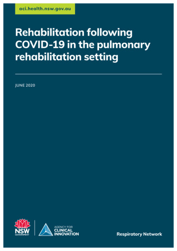
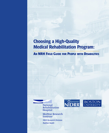
8REHABILITATION OF WATER MAINSThe aim of the selection process is to consider all these factors and to arrive at themost cost-effective, technically viable solution. Ideally, the cost estimate should includenot only direct contracting and related costs but also indirect costs associated with publicdisruption and longer-term maintenance and other life-cycle costs.One approach to rehabilitation method selection is summarized in Figures 1-2, 1-3,and 1-4. Together, these charts provide a framework for selecting or rejecting groups ofrehabilitation methods, depending on the nature of the performance problems, hydraulicrequirements, and some site-specific factors. In some cases, the charts indicate use of lining techniques classified as either Class I (nonstructural), Class II/III (semistructural), orClass IV (structural). A more detailed discussion of this classification system and of otherkey design issues associated with such lining techniques is presented in appendix A.The figures do not list cleaning as a solution for water quality or flow and pressureproblems. Cleaning with one of the various techniques discussed in the manual may welloffer the lowest-cost immediate solution to many of these problems. It may offer a longterm solution if repeated as required or combined with chemical treatment of water toprevent or delay recurrence of the original problem. However, cleaning is more frequentlyused as a necessary preliminary step before carrying out one of the lining processesdescribed in the manual.Pipe providespoor water qualityPipe hasstructuralproblemsGo to Figure 1-4Figure 1-2Pipe does nothave structuralproblemsPipe hasflow/pressure orleakage problemsPipe does not haveflow/pressure orleakage problemsGo to Figure 1-3Aggressive/softwater?No to allYes to anyCement liningEpoxy liningEpoxyliningSelection of rehabilitation techniques to resolve water quality problemsCopyright 2014 American Water Works Association. All Rights Reserved.AWWA Manual M28
Pipeline Renewal Methods 9Pipe has poorflow/pressureand/orexcessiveleakagePipe does nothave structuralproblemsPipe hasstructuralproblemsGo to Figure 1-4Renovated pipewould giveadequatehydraulicperformanceRenovated pipewould giveinadequatehydraulicperformanceMany connections?Easy excavation/restoration?Low social disruption?Yes to anyNo to allR(C)R(C) R(PB)Pipe hasexcessiveleakagePipe does nothaveexcessive leakageMany connections?Easy excavation/restoration?Low social disruption?Aggressive/softwater?Yes to anyNo to allNo to allYes to anyR(C)Joint Seals(D 16”)Joint Seals(D 16”)R(C) R(PB)R(SL) L(4)L(2/3)Cement liningEpoxy liningEpoxy liningNotes:R(C)—Replacement (conventional or boring/directional drilling)R(PB)—Replacement (pipe bursting)R(SL)—Replacement (sliplining)L(2/3)—Lining (semistructural—Class II/III)L(4)—Lining (structural—Class IV)Figure 1-3 Selection of rehabilitation techniques to resolve flow, pressure, and leakage problemsAWWA Manual M28Copyright 2014 American Water Works Association. All Rights Reserved.
10REHABILITATION OF WATER MAINSPipe has structural problemsRenovated pipewould preservestructural integrityof pipeRenovated pipewould not preservestructural integrityof pipeRenovated pipewould giveadequatehydraulicperformanceRenovated pipewould giveinadequatehydraulicperformanceRenovated pipewould giveinadequatehydraulicperformanceRenovated pipewould giveadequatehydraulicperformanceMany connections?Easy excavation/restoration?Low social disruption?Many connections?Easy excavation/restoration?Low social disruption?Many connections?Easy excavation/restoration?Low social disruption?Many connections?Easy excavation/restoration?Low social disruption?Yes to anyR(C)No to allYes to anyNo to allYes to anyNo to allYes to anyNo to allR(C) R(PB)R(SL) L(4)R(C)R(C) R(PB)R(C)R(C) R(PB)R(C)R(C) R(PB)R(SL) L(4)L(2/3)Notes:R(C)—Replacement (conventional or boring/directional drilling)R(PB)—Replacement (pipe bursting)R(SL)—Replacement (sliplining)L(2/3)—Lining (semistructural—Class II/III)L(4)—Lining (structural—Class IV)Figure 1-4 Selection of rehabilitation techniques to resolve structural problemsREFERENCEAmerican National Standards Institute (ANSI). 2012. Drinking Water System Components—Health Effects.NSF/ANSI 61-2012. 198. Ann Arbor, Mich.: NSF International.Copyright 2014 American Water Works Association. All Rights Reserved.AWWA Manual M28
AWWA MANUALM28Chapter2PreconstructionActivitiesADVANCE PLANNING CONSIDERATIONSPrior to undertaking a water main rehabilitation project or program, advance planningshould be undertaken to fully understand the effects such a project will have on theaffected customers, the community at large, and with other public agencies, and todetermine strategies to mitigate the negative impacts such projects produce.The reasons a utility decides to undertake water main rehabilitation will vary (seechapter 1 for discussion on water main rehabilitation techniques) and the method chosenwill reflect those parameters. However, it is important to recognize that different watermain rehabilitation techniques may impact the community differently. Therefore, it isimportant to have a clear understanding how each water main rehabilitation technique isperformed and what the impacts will be to the community.Once the water main rehabilitation technique has been determined, the utilityshould begin to develop a scope of work for the project and determine the overall projectboundaries or hire an agent to do so. Once all the affected streets have been determined,the project team should begin the coordination process with other public agencies, such asthe street paving department, to ensure that any streets that are planned for resurfacingcan be rescheduled so the resurfacing work is done after the water main rehabilitationwork has been completed. Likewise coordination with the other public agencies shouldbe planned to prevent competing construction projects within the same right-of-way. Thelocal governmental representative should also be notified of proposed work within theirarea of responsibility.11Copyright 2014 American Water Works Association. All Rights Reserved.
12REHABILITATION OF WATER MAINSBecause weather may play a key role in the success of certain water main rehabilitation techniques, it is important that projects are planned with seasonal weather patternsin mind. Projects that encompass sensitive environmental areas need additional planningand mitigation efforts to avoid negative impacts to those areas.PREPARATION OF PLANS AND
Biofilms also form readily in raw water systems or portions of the finished water system where water is high in iron or manganese or other nutrients. Such biofilms take the form of slimes, i.e., soft and filamentous. Even where scales do not form, these biofilms can severely affect water clarity and produce taste-and-odor problems. They can also