Transcription
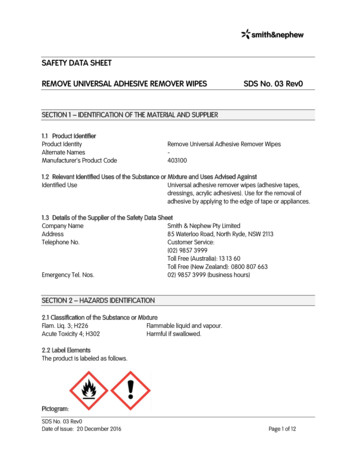
USB-MSD-RDU S B M A S S ST O R A G E D E V I C E R E F E R E N C E D E S I G N K I T U S E R ’S G U I D E1. Kit ContentsCF, SD, MMC Memory Expansion Board (AB5)256 MB SD CardStraight DB9 serial cable (RS-232 cable)Quick-start GuideReference Design Kit CD-ROM containing the following items:USB Mass Storage Device Reference Design Programmer's Guide (AN282), and associated software (AN282SW.zip)Keil Software 8051 Development Tools (evaluation assembler, 2 kB limited compiler, and linker)All C8051F340 and USB MSD related documentation in PDF format2. RequirementsThe USB MSD Reference Design Kit has been designed for use with a C8051F340DK Development Kit. Thedevelopment kit can be purchased separately from Silicon Laboratories (www.silabs.com). The following are therequirements to use this Reference Design Kit as described in this User's Guide.C8051F340DK Development Kit (contents shown below):C8051F340-TB Target BoardUSB Debug Adapter6' USB CableAC to DC Power AdapterPC with the following features:Operating system: Windows 2000/XP/Server2003Available ports: One serial port (RS232) and one USB portNote: A full version of the Keil tool chain is required in order to modify and recompile the code provided with this referencedesign because the code size is greater than evaluation tool chain's code size limits. No tool chain is required for thedemonstration or for debugging because an object file (*.OMF) is provided with the reference design.3. USB Mass Storage Device Reference Design Kit OverviewThe USB Mass Storage Device (MSD) Reference Design Kit includes the AB5 Expansion Board (shown inFigure 1) that can be connected directly to the expansion connector of a C8051F340-TB Target Board. Theconnected setup with a SD memory card is shown in Figure 2. This hardware and the included 'F340 firmware fullydemonstrate how an application can benefit from implementing the USB MSD device class. The firmware isdescribed in Section “4. USB MSD RD Firmware”. Step-by-step demonstration instructions are provided in Section“5. USB MSD Reference Design Kit Demonstration”. Detailed descriptions of the components and API functionsare included in “AN282: USB Mass Storage Device Reference Design Programmer's Guide". The board hardwareis described in sections 6, 7, and 8.Rev. 0.1 5/06Copyright 2006 by Silicon LaboratoriesUSB-MSD-RD
USB-MSD-RDFigure 1. CF, SD, MMC Memory Expansion Board (AB5)Note: The C8051F340-TB Target Board is not included with the USB-MSD-RD Kit.Figure 2. C8051F340-TB connected to AB5 Expansion Board with SD Card2Rev. 0.1
USB-MSD-RD4. USB MSD RD FirmwareThe USB MSD RD includes all the 'F340 firmware necessary to handle the following:USB enumeration and standard requestsMSD class requestsSCSI command setMedia access - SD, MMC and CompactFlash card formatsFAT16 file system supportAlso included is an example application that can perform the following tasks:Present an interactive command shell via the UARTMeasure temperature using the on-chip temperature sensor and ADCMonitor the state of the two push-button switches on the target boardLog the temperature and button state information to log files in the memory cardThe USB MSD RD System Architecture shown in Figure 3 gives an overview of the various components thatconstitute the USB MSD RD firmware. The code space usage chart in Figure 4 shows the amount of code spaceused by the firmware components. Detailed descriptions of the components and API functions are included in“AN282: USB Mass Storage Device Reference Design Programmer's Guide".To implement your own application based on this USB MSD Reference Design, you can customize the blockslabeled 'Application', 'Other HW Peripherals', and 'App. Specific Hardware' (all shown in blue in Figure 3). Sourcecode for all the other firmware blocks is also provided, but typically there is no need to customize these blocks.Rev. 0.13
USB-MSD-RDComponents used onlyfor USB MSD Data FlowFile system API servingthe Example App.Example App. componentsthat can be customizedUSB MSD Data FlowShared media accesscomponentsExample App. Data FlowWindows Explorer orOther ApplicationHyperTerminalDriver StackDriver StackUSB Host ControllerC8051F340 USB Mixed Signal MCUUSB FunctionControllerPCRS232 Serial PortTemp. SensorUSBMass sExampleApplicationFile SystemExternal HW PeripheralsCompactFlashMemoryCardSector ServerMedia AccessSPIC8051F340-TB Target BoardSD /MMCMemoryCardAB5 MemoryExpansion BoardFigure 3. USB MSD RD System Architecture4Rev. 0.1
USB-MSD-RDFile System(5.9 kB)9%AvailableFree Space(39.1 kB)62%ExampleApplication(5.1 kB)8%CompilerLibraries /Misc(5.1 kB)8%Used(23.9 kB)38%USB / MSD /SCSI (3.9 kB)6%Sector Server(1.1 kB)2%SD / MMCMedia Access(2.1 kB)3%CF MediaAccess(0.7 kB)1%Figure 4. USB MSD Firmware Code Space Usage on the C8051F340Rev. 0.15
USB-MSD-RD5. USB MSD Reference Design Kit DemonstrationThe following step-by-step demonstration will walk you through the various features and capabilities of thisreference design. There are three parts to this demonstration: Firmware Download, Example ApplicationDemonstration, and Mass Storage Device Demonstration.Note: The demonstration instructions assume that a PC running Windows 2000/XP/Server2003 is being used.5.1. Firmware DownloadThe steps in this section will guide you in downloading the USB MSD Reference Design firmware to theC8051F340-TB target board.1. Follow the 'Software Setup' instructions in the C8051F340DK User's Guide to install the Silicon LaboratoriesIDE. This document is available at the following web page: http://www.silabs.com/tgwWebApp/public/web DK.htm.2. Depending on which type of debug adapter you have, set up the hardware as shown in one of the two diagramsbelow (Figure 5, Figure 6). Consult the C8051F340DK User's Guide for detailed erialAdapterTargetBoardSerial PortFigure 5. Hardware Setup using a Serial Debug AdapterAC/DCAdapterPCUSBCableUSB PortUSBDebugAdapterRibbon CableTarget BoardFigure 6. Hardware Setup using a USB Debug Adapter3. Launch the Silicon Labs IDE using the icon from your Start Menu: 'Start Menu Programs SiliconLaboratories Silicon Laboratories IDE'4. Before connecting to the target device, several connection options may need to be set. Open the 'ConnectionOptions' window by selecting 'Options Connection Options.' in the IDE menu. First, select the adapter thatwas included with the kit in the "Serial Adapter" section. Next, the correct "Debug Interface" must be selected.C8051F34x family devices use the Silicon Labs 2-wire (C2) debug interface. Once these selections are made,click the OK button to close the window.6Rev. 0.1
USB-MSD-RD5. Click the 'Connect' button in the toolbar or select 'Debug Connect' from the menu to connect to the device.You will see the text "Target: C8051F340" in the status bar of the IDE if the connection was successful.6. Choose the 'Project Download Object File ' option. This shows a 'Download' dialog. Click the 'Browse'button and select the USB MSD RD firmware pre-linked OMF file from this path:C:\Silabs\MCU\USB MassStorageDevice RD\Firmware\F34x MSD.OMF7. Click the 'Download' button to download this firmware to the 'F340 device. You will see the text "Downloadsuccessful" in the Build window if the firmware was downloaded successfully.8. Disconnect the dc power adapter and the ribbon cable from the target board.5.2. Example Application DemonstrationThe Example Application demonstrates how the reference design can be used as an independent embeddedsystem while it is not connected to a PC via USB. In this configuration, the embedded system is able to performvarious tasks based on user commands via a UART-based interactive command shell.5.2.1. PC Software SetupOn the PC, set up HyperTerminal to use the COM port at 115200 baud, 8-N-1, and no flow control as shown inFigure 7. Detailed setup instructions are shown below.1. Launch HyperTerminal from your Start Menu: 'Start Menu Programs Accessories Communications HyperTerminal'.2. Type any name for the new connection, and click OK.3. In the 'Connect using:' drop-down list, Choose 'COM1', or if you have multiple COM ports, choose the one youwant to use.4. Set up the COM1 Properties dialog as shown in Figure 7, and click OK.Figure 7. Example Application - HyperTerminal SettingsRev. 0.17
USB-MSD-RD5.2.2. Hardware Setup1. Connect the C8051F340-TB target board connector J13 to the AB5 expansion board connector J1.2. Insert the SD card provided with the reference design kit into the SD card slot (M2) in the expansion board.3. Connect a straight DB9 serial cable (RS-232 cable) between the PC's serial port and C8051F340-TB.4. Make sure that the jumpers on the 'F340 TB are as shown in Figure 8.5. Apply power to the target board using a dc power adapter.C8051F340-TB Target BoardJ13J13R10SILICON LABORATORIESJ6SW3SW23D4J1SD / MMCCard SlotP4P4SW1RS232RS232D3DB9SerialCableto PCSILICON LABORATORIESM2J5J12P3P3U1J4J19J15J11J3M1P2AB5 (CF, SD, MMC MemoryExpansion shCard SlotJ8J2D2DEBUG2P2.0 RESETJ7 J10SDCardP2.1J16J1J17AB5 Expansion BoardJ9P14AC-to-DCPower AdapterPWRFigure 8. Demonstration Connections5.2.3. Interacting with the Example Application1. A command interpreter shell is presented via HyperTerminal. Use this to interact with the device firmware torecord a temperature log. Follow the steps below referring to screenshot in Figure 9.Note: If the text "USB Active; UART Disabled" is displayed even when a USB cable is not plugged into the USB connector onthe board, it most likely is because of error(s) in jumper settings. See Figure 8 for the correct jumper settings.a. Type "calibrate 25" to calibrate the device to room temperature (25 ºC).b. Type "templog temp.txt" to initiate temperature logging to a file that is updated every second. This is an example ofperiodic logging, where the interval between logs is known in advance. The 'F340 ADC0 measures the temperatureusing the on-chip temperature sensor, which is then logged to a file.c. Wait for a few seconds to collect some temperature data in the file.d. Type "templog" to stop the log.e. Type "type temp.txt" to view the contents of the log file.8Rev. 0.1
USB-MSD-RDFigure 9. Example Application - Temperature loggingRev. 0.19
USB-MSD-RD2. Continue to use the command interpreter shell to log press/release events for the buttons P2.0 and P2.1 on theC8051F340 target board. Follow the steps below and also refer to Figure 10.a. Type "log button.txt" to initiate button press/release logging to a file that is updated every time a button press or releaseevent occurs. This is an example of asynchronous logging, where the interval between logs is not known in advance. Theevents are logged with the time value in milliseconds that shows the time since the last event.b. Press buttons labeled "P2.0" and "P2.1" repeatedly for a few times in any order you wish.c. Type "log" to stop the log.d. Type "type button.txt" to view the contents of the log file.Figure 10. Example Application - Button state logging3. In addition to the above commands, you can also try other commands supported by the command interpretershell. An index of all commands supported by the example application is available in “Appendix A—CommandInterpreter Shell Reference”.10Rev. 0.1
USB-MSD-RD5.3. Mass Storage Device DemonstrationThis demonstrates the 'F340 device firmware support for the standard USB Mass Storage Device class. TheHyperTerminal interactive command shell is deactivated whenever the device is plugged into the PC via a USBcable. This is to protect against simultaneous access of the file system by the PC and the example application.1. Connect a USB cable between the PC and the C8051F340-TB target board.2. The operating system will detect the new hardware, recognize it as a standard USB Mass Storage Device, andinstall appropriate drivers. There should be no need for any user interaction during this phase. At the end of thisprocess, you will see three entries in Device Manager, and you should also see a Removable Disk in WindowsExplorer. See Figures 11 and 12.Figure 11. USB Mass Storage Device - Device ManagerRev. 0.111
USB-MSD-RDFigure 12. USB Mass Storage Device - Windows Explorer3. The files created during the previous example application demonstration will be visible. Files can be viewed,added, deleted, copied or moved using Windows Explorer.4. To disconnect the device, click on the icon with the green arrow in the system tray and select "Safely RemoveUSB Mass Storage Device". See Figure 13. You can unplug the USB cable from the C8051F340-TB TargetBoard after you see a message informing you that it is safe to do so. Unplugging the USB cable will restorecontrol to the HyperTerminal-based command interpreter shell.Figure 13. USB Mass Storage Device - Safe Device Removal12Rev. 0.1
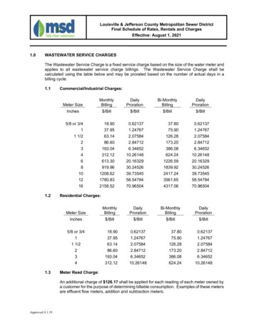
USB-MSD-RD6. CF, MMC, SD Memory Expansion Board (AB5)The CF, MMC, SD Memory Expansion Board contains a SD/MMC card slot, a CompactFlash card slot, and apower gating FET that allows control of power to the expansion board via software. The pin connections are shownin Table 1. The board schematic is shown in Figure 14.Table 1. CF, SD, MMC Memory Expansion Board Pin ctionDescriptionPOWERA1 3VDDigital PowerGNDB1GNDDigital GroundADD0B16P3.5CF Address bit 0ADD1A16P3.6CF Address bit 1ADD2C15P3.7CF Address bit 2DA0B15P4.0CF Data bit 0DA1A15P4.1CF Data bit 1DA2C14P4.2CF Data bit 2DA3B14P4.3CF Data bit 3DA4A14P4.4CF Data bit 4DA5C13P4.5CF Data bit 5DA6B13P4.6CF Data bit 6DA7A13P4.7CF Data bit 7SCKC12P0.0SD/MMC SPI ClockMISOB12P0.1SD/MMC SPI Master In, Slave OutMOSIA12P0.2SD/MMC SPI Master Out, Slave InNSSC11P0.3SD/MMC SPI Slave SelectOEA23P1.1CF Output EnableCE1C22P1.2CF Card EnableCD1B22P1.3CF Card DetectRDYA22P1.4CF Ready SignalRESETC21P1.0CF Reset SignalWEB21P1.6CF Write EnablePWR ONA21P1.7Expansion board global power controlRev. 0.113
14Rev. 0.1PWR 3742243993635344120191817161514121110838GND DA6DA7R110kVCCR210kR44k7VCCR54k7GNDResistors R3.R5 are optionalR34k7Figure 14. CF, MMC, SD Memory Expansion Board (AB5) - SchematicGNDVCCC1 VCCGNDNSSMOSIMISOSCKC2 USB-MSD-RD7. Schematic
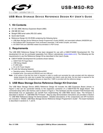
C1 C2C3J1M1M2T1304050607080Rev. 0.110101000R3 R4 7MEMORY CARD256MB SECUREDIGITALMOSFET P-CH 20V5.3A 8-SOICSD Card Connector256MBIRF7204CARDMMCE715B-LFCF Card Connector CARD-CF50C10ConnectorCAP 1.0UF 16VCERAMIC X7R 1206CAP .10UF 50VCERAMIC X7R 0805RES 100K OHM1/8W 5% 0805 SMDRES 10K OHM 1/8W5% 0805 SMDDO NOT POPULATEMemory CardR72090R1 R210Pos. ReferenceDesignator8. Bill of ternationalRectifierYageo AmericaYageo AmericaYageo AmericaYageo 7R9BB104RC0805JR-07100KLRC0805JR-0710KLTolerance Voltage Dielectric Qty per Manufacturer Manufacturer Part i-KeyDigi-KeyDigi-KeyDigi-KeySupplierSecure Digital T-ND311-10KARCT-NDSupplier Part tprintUSB-MSD-RD15
USB-MSD-RDAPPENDIX A—COMMAND INTERPRETER SHELL REFERENCECommand Interpreter Shell - Communication ParametersBaud rate: 115200 bpsData format: 8 data bits, 1 stop bit, no parityFlow control: NoneCommand Interpreter Shell - Supported CommandsThe interactive command interpreter shell presented by the example application via the UART supports a set ofMS-DOS-like commands. Table 2 lists the supported commands along with explanations.Table 2. Command Interpreter Shell - Supported CommandsCommandExplanationCLSClear the screen.DIRShow the contents of the current directory.MD dirname Make “dirname”directory. If “dirname” is incorrect or already exists, an error message isreturned.CD dirname Change to “dirname” directory. If “dirname” is incorrect or does not exist in the presentdirectory, an error message is returned.RD dirname Remove “dirname” directory. If “dirname” is incorrect, an error message is returned.IMPORTANT: No check is done on “dirname” directory contents before removal.TYPE filename Show the ASCII contents of a file in the current directory.DEL filename Delete a file in the current directory.FORMATFormat the existing FAT16 partition. Note: This will not work properly if the existing filesystem is of a format other than FAT16. See “Appendix B—Formatting a Memory Card”for instructions on how to format a new disk.S nnnnn Show the contents of the nnnnn-th 512-byte block. Calling “S” without a parameter willprint the valid range of sectors.CHKDSKShow info about the formatting used.CALIBRATE val Sets offset for temperature sensor. ‘val’ should be current ambient temperature indegrees C.TEMPLOG filename Start background logging of ambient temperature. The logging is appended at the end ofthe specified file in the current directory. Calling “TEMPLOG” without a parameter willstop current logging, if any, and close that file.LOG filename 16Start background logging of the state of the two buttons (P2.1 and P2.2). The logging isappended at the end of the specified file in the current directory. Calling “LOG” without aparameter will stop current logging, if any, and close that file.Rev. 0.1
USB-MSD-RDCommand Interpreter Shell - Notes1. The commands are not case-sensitive.2. Wild cards (*,? etc) are not supported by the shell.3. Long file names are not supported by the shell. They are abbreviated to 8.3 format by removing unsupportedcharacters, truncating when longer than 8 characters, and adding a numbered suffix. This is done as describedin the following Microsoft Knowledge Base article: http://support.microsoft.com/?kbid 142982Example: If two files named 'abcdefghi.txt' and 'abcdefghk.txt' are placed in the one folder when the device is inPC mode, the "dir" command in Example Application mode will list them as 'abcdef 1.txt' and 'abcdef 2.txt',respectively.4. The 'dir' command shows the volume label as a separately entry, with the tag " LABEL " shown in theextension column.5. File creation/modification date and time stamps are not supported when the device is in Embedded SystemMode.Rev. 0.117
USB-MSD-RDAPPENDIX B—FORMATTING A MEMORY CARDThe USB MSD RD firmware supports the FAT16 file system. Memory cards formatted with other file systemscannot be used with this firmware. If the disk is already formatted as FAT16, and you want to reformat the disk, youcan do so using the "FORMAT" command available through the Example Application's Command Interpreter Shell.See “Appendix A—Command Interpreter Shell Reference” for details.Formatting using Windows Explorer:If the disk is formatted with a file system other than FAT16, or if you are not sure what file system is currently on thedisk, you can perform a new format on the disk using the "Format" command available in Windows Explorer.WARNING: Using the Format command will erase all data from the target disk, and is irreversible.Connect the system as described in Section “5.3. Mass Storage Device Demonstration”. After the device hasenumerated and shows up as a removable disk, open 'My Computer', right-click on the removable disk, andchoose 'Format'. In the following dialog, choose 'FAT' as the file system and click the 'START' button to start theformatting process. Optionally, you can enter a volume label as well.Limitations:Memory card sizes should be greater than 16 MB, up to a maximum of 4 GB.Windows formats memory card sizes up to 16 MB as FAT12, which is not supported by the USB MSD RDfirmware.The FAT16 file system supports memory sizes up to 4 GB.Troubleshooting:If the memory card does not appear as a valid USB Mass Storage Device when connected, it is most likelyformatted in a way that is not readable by the firmware (for example, a custom digital camera format). In this case,the card should be formatted using a dedicated memory card reader or other specialized device.18Rev. 0.1
USB-MSD-RDNOTES:Rev. 0.119
USB-MSD-RDCONTACT INFORMATIONSilicon Laboratories Inc.4635 Boston LaneAustin, TX 78735Tel: 1 (512) 416-8500Fax: 1 (512) 416-9669Toll Free: 1 (877) 444-3032Email: productinfo@silabs.comInternet: www.silabs.comThe information in this document is believed to be accurate in all respects at the time of publication but is subject to change without notice.Silicon Laboratories assumes no responsibility for errors and omissions, and disclaims responsibility for any consequences resulting fromthe use of information included herein. Additionally, Silicon Laboratories assumes no responsibility for the functioning of undescribed featuresor parameters. Silicon Laboratories reserves the right to make changes without further notice. Silicon Laboratories makes no warranty, representation or guarantee regarding the suitability of its products for any particular purpose, nor does Silicon Laboratories assume any liabilityarising out of the application or use of any product or circuit, and specifically disclaims any and all liability, including without limitation consequential or incidental damages. Silicon Laboratories products are not designed, intended, or authorized for use in applications intended tosupport or sustain life, or for any other application in which the failure of the Silicon Laboratories product could create a situation where personal injury or death may occur. Should Buyer purchase or use Silicon Laboratories products for any such unintended or unauthorized application, Buyer shall indemnify and hold Silicon Laboratories harmless against all claims and damages.Silicon Laboratories and Silicon Labs are trademarks of Silicon Laboratories Inc.Other products or brandnames mentioned herein are trademarks or registered trademarks of their respective holders.20Rev. 0.1
USB Debug Adapter 6' USB Cable AC to DC Power Adapter PC with the following features: Operating system: Windows 2000/XP/Server2003 Available ports: One serial port (RS232) and one USB port Note: A full version of the Keil tool chain is required in order to modify and recompile the code provided with this reference