Transcription
Double Hex DriverNCV7708FThe NCV7708F is a fully protected Hex Half Bridge Driverdesigned specifically for automotive and industrial motion controlapplications. The six low and high side drivers are freely configurableand can be controlled separately. This allows for high side, low side,and H Bridge control. H Bridge control provides forward, reverse,brake, and high impedance states. The drivers are controlled via astandard SPI interface.www.onsemi.comMARKINGDIAGRAMSFeatures Ultra Low Quiescent Current Sleep ModeSix Independent High Side and Six independent Low Side DriversIntegrated Freewheeling Protection (LS and HS)Internal Upper and Lower Clamp DiodesConfigurable as H Bridge DriversRDS(on) 0.6 W (typ)5 MHz SPI ControlSPI Valid Frame DetectionCompliance with 5 V and 3.3 V SystemsOvervoltage LockoutUndervoltage LockoutFault ReportingCurrent LimitOvertemperature ProtectionInternally Fused Lead in SOIC 28SSOP 24 NB EPADThese are Pb Free DevicesTypical Applications Automotive Industrial DC Motor ManagementSOIC 28DW SUFFIXCASE 751FSSOP 24 NB EPDQ SUFFIXCASE 940AKXAWLYYWWGNCV7708F XAWLYYWWGNCV7708F XAWLYYWWG Optional Wafer Fab Indicator Assembly Location Wafer Lot Year Work Week Pb Free PackageORDERING OIC 28W(Pb Free)1000 /Tape & ReelNCV7708FDQR2GSSOP 24N(Pb Free)1000 /Tape & Reel†For information on tape and reel specifications,including part orientation and tape sizes, pleaserefer to our Tape and Reel Packaging SpecificationsBrochure, BRD8011/D.*Contact your local sales representative for theNCV7708F device availability in SOIC 28 package. Semiconductor Components Industries, LLC, 2017April, 2021 Rev. 41Publication Order Number:NCV7708F/D
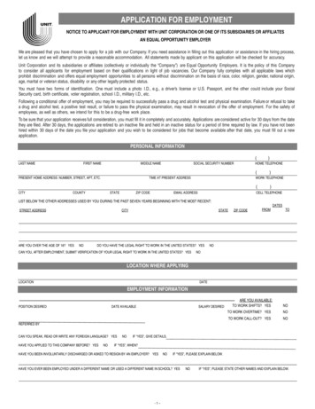
NCV7708FVS2VS1ENCPVS2’ChargePumpHigh SideDriverOUTH1WaveshapingControlLogicVCCVRAIL PORLOGICBIASVRAIL Low �ANALOGBIASENABLEDRIVE 1VSVS16 BitLogicandLatchSPISCLKOUTL1WaveshapingUnder loadOvercurrentThermalWarning/ShutdownOUTH2VSDRIVE 2CSBOUTL2CPVSOUTH3DRIVE 3VS1UndervoltageLockoutCPOUTL3VSOUTH4VS2DRIVE 4OUTL4CPVS1VSOvervoltageLockoutOUTH5DRIVE 5VS2CPOUTL5VSOUTH6DRIVE 6CPGNDFigure 1. Block Diagramwww.onsemi.com2OUTL6
L3OUTH3OUTH2OUTL21SOIC 28OUTH6OUTL6SISCLKCSBGNDGNDVCCSOENOUTL1OUTH1SSOP 24Figure 2. Pin ConnectionPIN DESCRIPTIONPin No.SSOP 24SOIC 28Symbol11OUTL5Output Low Side 5. Open drain output driver with internal reverse diode.22OUTH5Output High Side 5. Open source output driver with internal reverse diode. Drain connected toVS2’.33OUTH4Output High Side 4. Open source output driver with internal reverse diode. Drain connected toVS2’.44OUTL4Output Low Side 4. Open drain output driver with internal reverse diode.55VS2Power Supply input for the High Side Output Drivers 4, 5, and 6.66GNDGround77GNDGround 8GNDGround 9GNDGround810VS1Power Supply input for the High Side Output Drivers 1, 2, and 3Description911OUTL3Output Low Side 3. Open drain output driver with internal reverse diode.1012OUTH3Output High Side 3. Open source output driver with internal reverse diode. Drain connected toVS1’.1113OUTH2Output High Side 2. Open source output driver with internal reverse diode. Drain connected toVS1’.1214OUTL2Output Low Side 2. Open drain output driver with internal reverse diode.1315OUTH1Output High Side 1. Open source output driver with internal reverse diode. Drain connected toVS1’.1416OUTL1Output Low Side 1. Open drain output driver with internal reverse diode.1517ENEnable. Input high wakes the IC up from sleep mode.1618SOSerial Output. 16 bit serial communications output.1719VCCPower supply input for Logic.1820GNDGround1921GNDGround 22GNDGround 23GNDGround2024CSBChip Select Bar. Active low serial port operation.2125SCLKSerial Clock. Clock input for use with SPI communication.2226SI2327OUTL6Output Low Side 6. Open drain output driver with internal reverse diode.2428OUTH6Output High Side 6. Open source output driver with internal reverse diode. Drain connected toVS2’.EPAD EPADSerial Input. 16 bit serial communications input.Connect to Ground for best thermal performance or leave unconnected.www.onsemi.com3
NCV7708FMAXIMUM RATINGSRatingValuePower Supply Voltage (VS1, VS2)(DC)(AC), t 500 ms, Ivsx 2 A 0.3 to 40 1.0Output Pin OUTHx(DC)(AC – inductive clamping) 0.3 to 40 8.0Output Pin OUTLx(DC)(AC), t 500 ms, IOUTLx 2 A(AC Inductive Clamping) 0.3 to 36 1.045Pin Voltage (Logic Input pins, SI, SCLK, CSB, SO, EN, VCC) 0.3 to 5.5UnitVVOutput Current (OUTL1, OUTL2, OUTL3, OUTL4, OUTL5, OUTL6, OUTH1, OUTH2, OUTH3, OUTH4,OUTH5, OUTH6)(DC) Vds 12 V(DC) Vds 20 V(DC) Vds 40 V(AC) Vds 12 V, (50 ms pulse, 1 s period)(AC) Vds 20 V, (50 ms pulse, 1 s period)(AC) Vds 40 V, (50 ms pulse, 1 s period)VVA 1.5 to 1.5 0.7 to 0.7 0.25 to 0.25 2.0 to 2.0 0.9 to 0.9 0.3 to 0.3Electrostatic Discharge, Human Body Model, VS1, VS2, OUTx (Note 1)4.0kVElectrostatic Discharge, Human Body Model, all other pins2.0kVElectrostatic Discharge, Machine Model200VElectrostatic Discharge, Charged Device Model1.0kVShort Circuit Reliability Characterization (AEC Q10x)GRADE A Operating Junction Temperature 40 to 150 CStorage Temperature Range 55 to 150 CMSL 3MSL 2 260 CMoisture Sensitivity LevelSOIC 28SSOP 24 EPADPeak Reflow Soldering Temperature: Pb Free, 60 to 150 seconds at 217 C (Note 2)Stresses exceeding those listed in the Maximum Ratings table may damage the device. If any of these limits are exceeded, device functionalityshould not be assumed, damage may occur and reliability may be affected.1. Tested with a VS1/VS2 power supply common point.2. For additional information, please see or download the ON Semiconductor Soldering and Mounting Techniques Reference Manual,SOLDERRM/D.THERMAL CONDITIONSTest Conditions, Typical ValueBoard Details (Note 3)Board Details (Note 4)UnitJunction to Lead (psi JL8, YJL8) or Pins 6 9, 20 231011 C/WJunction to Ambient (RqJA, qJA)7863 C/WJunction to Board (RYB) 2 C/WJunction to Ambient (RqJA) 54 C/WJunction to Lead (RYJL) 7 C/WThermal ParametersSOIC 28SSOP 24 EPAD3. 1 oz copper, 240 mm2 copper area, 0.062″ thick FR4. This is the minimum pad board size.4. 1 oz copper, 986 mm2 copper area, 0.062″ thick FR4.www.onsemi.com4
NCV7708FRECOMMENDED OPERATING CONDITIONSValueSymbolMinMaxUnitDigital Supply Input Voltage (VCC)VCCmax3.155.25VBattery Supply Input Voltage (VS)VSmax5.528VDC Output Current (I(OUTLx), I(OUTHx))DCmax 0.5ATJ 40150 CRatingJunction TemperatureFunctional operation above the stresses listed in the Recommended Operating Ranges is not implied. Extended exposure to stresses beyondthe Recommended Operating Ranges limits may affect device reliability.ELECTRICAL CHARACTERISTICS( 40 C TJ 150 C, 5.5 V VSx 40 V, 3.15 V VCC 5.25 V, EN VCC, unless otherwise specified)SymbolTest ConditionsSupply Current (VS1 VS2)Sleep Mode (Note 5)Ivs sleepSupply Current (VS1)Active ModeIvs1 actCharacteristicMinTypMaxUnitVS1 VS2 13.2 V,VCC CSB 5 V,EN SI SCLK 0 V( 40 C to 85 C) 1.02.5mAEN VCC,5.5 V VSx 35 VNo Load 1.252.5mACSB VCC,EN SI SCLK 0 V( 40 C to 85 C) 1.02.5mA 1.53.0mA 1.252.5mA 2.552.9V3.74.14.5VGENERALSupply Current (VCC) Sleep Mode (Note 5)Ivcc sleepSupply Current (VCC) Active ModeIvcc actEN CSB VCC,SI SCLK 0 VSupply Current (VS2)Active ModeIvs2 actEN VCC,5.5 V VSx 35 VNo LoadVCC Power On Reset ThresholdVCCporVSx Undervoltage Detection ThresholdVSuvVSx Undervoltage Detection HysteresisVSuv hys100365450mV3336.540.0VVSov hys12.54.0VVSx Overvoltage Detection ThresholdVSovVSx Overvoltage Detection HysteresisThermal Warning (Note 6)Thermal Warning Hysteresis (Note 6)Thermal Shutdown (Note 6)Ratio of Thermal Shutdown to ThermalWarning (Note 6)VSx decreasingVSx increasingTtw120140170 CTtw hys 20 CTtsd155175195 CTtsd/Ttw1.051.20 0.6 1.31.7 5.0 1.0 OUTPUTSOutput High RDS(on) (source and sink)Source Leakage CurrentRDSon srcRDSon snkIout 500 mA25 C 40 C TJ 150 CIsrcOUTH(1 6) 0 V,Vsx 40 V, VCC 5 VOUTH(1 6) 0 V,Vsx 13.2 V, VCC 5VWmAProduct parametric performance is indicated in the Electrical Characteristics for the listed test conditions, unless otherwise noted. Productperformance may not be indicated by the Electrical Characteristics if operated under different conditions.5. For temperatures above 85 C, refer to graphs for VSx and VCC Sleep Current vs. Temperature on page 17.6. Thermal characteristics are not subject to production test.7. Refer to “Typical High Side Negative Clamp Voltage” graph on page 17.8. Current limit is active with and without overcurrent detection.9. Not production tested.www.onsemi.com5
NCV7708FELECTRICAL CHARACTERISTICS( 40 C TJ 150 C, 5.5 V VSx 40 V, 3.15 V VCC 5.25 V, EN VCC, unless otherwise specified)CharacteristicSymbolTest ConditionsMinTypMaxUnit 5.0 1.0 0.91.3VOUTPUTSSink Leakage CurrentIsnkPower Transistor Body Diode Forward VoltageVbd fwdHigh Side Clamping Voltage (Note 7)Vclp hsOUTL(1 6) 34 V,VCC 5 VOUTL(1 6) 34 V,VCC 5 V, T 25 CIF 500 mA 0.7VI(OUTLx) 50 mA36 45VIul lsVCC 5 V, Vsx 13.2 V2.08.016mAUnder Load Detection Threshold (OUTHx)Iul hsVCC 5 V, Vsx 13.2 V 16 8.0 2.0mAUnder Load Detection Delay Timetul delVCC 5 V, Vsx 13.2 V200350600msOvercurrent Shutdown Threshold (OUTHx)Iocsd hsVCC 5 V, Vsx 13.2 V,Bit13 1 2.0 1.45 1.1AOvercurrent Shutdown Threshold (OUTLx)Iocsd lsVCC 5 V, Vsx 13.2 V,Bit13 11.11.452.0ALow Side Clamping VoltageVclp lsI(OUTHx) 50 mAmAUNDER LOADUnder Load Detection Threshold (OUTLx)OVERCURRENTOvercurrent Shutdown Delay Timetocsd 0tocsd 1VCC 5 V, Vsx 13.2 V,Bit13 0Bit13 180102002540050msmsCurrent Limit (OUTHx)Ilim hsVCC 5 V, Vsx 13.2 V 5.0 3.0 2.0ACurrent Limit (OUTLx)Ilim lsVCC 5 V, Vsx 13.2 V2.03.05.0AVinth2.0 0.8VInput Hysteresis (SI, SCLK, CSB)Vinhys spi100300600mVInput Hysteresis (EN)Vinhys en100400800mVCURRENT LIMIT (Note 8)LOGIC INPUTS (EN, SI, SCLK, CSB)Input Threshold HighInput Threshold LowPull down Resistance (EN, SI, SCLK)RpdEN SI SCLK VCC50125250kWPull up Resistance (CSB)RpuCSB 0 V50125250kWInput Capacitance (Note 9)CIN 1015pFVCC – 1.0VCC – 0.7 VLOGIC OUTPUT (SO)Output HighVsohIout 1 mAOutput LowVsolIout 1.6 mATri state LeakageIsoCSB VCC,0 V SO VCCTri state Input Capacitance (Note 9)CsoHigh Side Turn On Time 0.20.4V 10 10mACSB VCC,0 V VCC 5.25 V 1015pFthsonVs 13.2 V, Rload 25 W 7.513msHigh Side Turn Off TimethsoffVs 13.2 V, Rload 25 W 3.06.0msLow Side Turn On TimetlsonVs 13.2 V, Rload 25 W 6.513msTIMING SPECIFICATIONSProduct parametric performance is indicated in the Electrical Characteristics for the listed test conditions, unless otherwise noted. Productperformance may not be indicated by the Electrical Characteristics if operated under different conditions.5. For temperatures above 85 C, refer to graphs for VSx and VCC Sleep Current vs. Temperature on page 17.6. Thermal characteristics are not subject to production test.7. Refer to “Typical High Side Negative Clamp Voltage” graph on page 17.8. Current limit is active with and without overcurrent detection.9. Not production tested.www.onsemi.com6
NCV7708FELECTRICAL CHARACTERISTICS( 40 C TJ 150 C, 5.5 V VSx 40 V, 3.15 V VCC 5.25 V, EN VCC, unless otherwise specified)CharacteristicSymbolTest ConditionsMinTypMaxUnitLow Side Turn Off TimetlsoffVs 13.2 V, Rload 25 W 2.05.0msHigh Side Rise TimethsrVs 13.2 V, Rload 25 W 4.08.0msHigh Side Fall TimethsfVs 13.2 V, Rload 25 W 2.03.0msLow Side Rise TimetlsrVs 13.2 V, Rload 25 W 1.02.0msLow Side Fall TimetlsfVs 13.2 V, Rload 25 W 1.03.0msNon Overlap TimethsOfflsOnHigh Side Turn Off To LowSide Turn On1.5 msNon Overlap TimetlsOffhsOnLow Side Turn Off To HighSide Turn On1.5 msTIMING SPECIFICATIONSProduct parametric performance is indicated in the Electrical Characteristics for the listed test conditions, unless otherwise noted. Productperformance may not be indicated by the Electrical Characteristics if operated under different conditions.5. For temperatures above 85 C, refer to graphs for VSx and VCC Sleep Current vs. Temperature on page 17.6. Thermal characteristics are not subject to production test.7. Refer to “Typical High Side Negative Clamp Voltage” graph on page 17.8. Current limit is active with and without overcurrent detection.9. Not production tested.ELECTRICAL CHARACTERISTICS( 40 C TJ 150 C, 5.5 V VSx 40 V, EN VCC 5 V, unless otherwise specified)ConditionsSymbolMinTypMaxUnitfSCLK 5.0MHztSCLK200500 nsSCLK High TimetCLKH85 nsSCLK Low TimetCLKL85 nstCLKSU1tCLKSU28585 nsSI Setup TimetSISU50 nsSI Hold TimetSIHT50 nsCSB Setup TimetCSBSU1tCSBSU2100100 nsCSB High Time (Note 10)tCSBHT5.0 msSO enable after CSB falling edgetSOCSBF 200nsCharacteristicSERIAL PERIPHERAL INTERFACE (VCC 5 V)SCLK FrequencySCLK Clock PeriodVCC 5 VVCC 3.3 VSCLK Setup TimeSO disable after CSB rising edgetSOCSBR 200nsSO Rise Time (10% to 90%)Cload 40 pFtSORISE 1025nsSO Fall Time (90% to 10%)Cload 40 pFtSOFALL 1025nsSO Valid Time (Note 11)SCLK High to SO 50%tSOV 50100nsProduct parametric performance is indicated in the Electrical Characteristics for the listed test conditions, unless otherwise noted. Productperformance may not be indicated by the Electrical Characteristics if operated under different conditions.10. This is the minimum time the user must wait between SPI commands.11. Not tested in productionwww.onsemi.com7
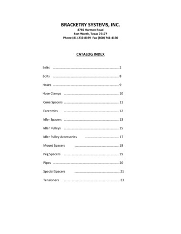
igure 3. SPI Timing Diagramwww.onsemi.com850%
NCV7708FSPI Communication1. CSB goes low to allow serial data transfer.2. A 16 bit word is clocked (SCLK) into the SI(serial input) pin. The SI input signal is latched onthe falling edge of SCLK.3. Current SO data is simultaneously shifted out onevery rising edge of SCLK starting with the LSB(TW).4. CSB goes high to transfer the clocked ininformation to the data registers.(Note: SO is tristate when CSB is high.)5. The SI data will be accepted when a valid SPIframe is detected. A valid SPI frame consists ofthe above conditions and a complete set ofmultiples of 16 bit words. Invalid frames areignored with previous input data intact.Standard 16 bit communication has been implementedfor the communication of this IC to turn drivers on and off,and to report faults. (Reference the SPI CommunicationFrame Format Diagram). The LSB (Least Significant Bit) isclocked in first.For SPI communication, the device must first be enabled(EN high). The SPI inputs are TTL compatible and the SOoutput high level is defined by the applied VCC. Theactive-low CSB input has a pull up resistor. SPIcommunication is active when CSB is low. Providing apull-up resistor insures the communication bus is not activeshould the communication link between the microcontrollerand NCV7708F become open. SCLK and SI havepull down resistors. This provides known states when theSPI is not active.Communication is implemented as H6OLDULDPSF123456789101112131415SCLKSOTW0Figure 4. SPI Communication Frame Formatwww.onsemi.com9
NCV7708FThe table below defines the programming bits anddiagnostic bits. Fault information is sequentially clocked outthe SO pin of the NCV7708F as programming informationis clocked into the SI pin of the device. Daisy chaincommunication between SPI compatible IC’s is possible byconnection of the serial output pin (SO) to the input of thesequential IC (SI).Output DataInput DataBit #Bit Description15Overvoltage Lock Out Control(OVLO)141312Under Load Detection ShutDown Control (ULD)Overcurrent Detection ShutDown Control (OCD)OUTH6Bit Status0 Disable1 Enable0 Disable1 Enable0 200 msec1 25 msec0 OffOUTL60 OffOUTH50 OffOUTL50 OffOUTH40 OffOUTL40 OffOUTH30 OffOUTL30 OffOUTH20 OffOUTL20 OffOUTH10 OffOUTL10 OffStatus Register Reset (SRR)12OUTH6*1 Fault0 Off11OUTL6*10OUTH5*9OUTL5*8OUTH4*0 Off0 Off0 Off0 1*0Thermal Warning (TW)0 Off0 Off0 Off0 Off0 Off0 Off0 Off1 On1 On00 No Fault1 Fault1 On1 On1Over Load Detect Signal(OLD)1 On1 On2131 On1 On30 No Fault1 Fault1 On1 On4Under Load Detect Signal(ULD)1 On1 On5141 On1 On60 No Fault1 On1 On7Power Supply Fail Signal(OVLO or UVLO PSF)1 On1 On8151 On1 On9Bit Status1 On1 On10Bit Description1 On1 On11Bit #0 No Reset0 Not in TW1 In TW1 Reset*Output Bits [1:12] represent the state of the designated outputs.Status Register Reset SRRpresent when SRR is sent, protection can be re engaged andshutdown can recur. The device can also be reset by togglingthe EN pin or by VCC power-on reset.When asserted, all latched faults are cleared (TW, OLD,ULD, and PSF).Sending SRR 1 clears status memory and reactivatesfaulted output. The previous SI data pattern must be sentwith SRR to preserve device configuration and output states.SRR takes effect at the rising edge of CSB. If a fault is stillwww.onsemi.com10
NCV7708FCHARACTERISTIC TIMING DIAGRAMSTlsTr90%TlsOff50%LS Turn OFF10%TlsOffHsOn90%50%HS Turn ON10%ThsTr50%ThsOnCSBLS Turn OnTlsTf90%50%TlsOn10%HS Turn OffThsOffLsOn90%50%10%ThsTf50%CSBThsOffFigure 5. Detailed Driver Timingwww.onsemi.com11
NCV7708FDETAILED OPERATING DESCRIPTIONGeneralAll low side drivers are powered by VRAIL via VCC.All drivers are initialized in the off (high impedance)condition. Power up sequencing of VCC, VS1, and VS2 is upto the user. The voltage on VS1 and VS2 should be operatedat the same potential. If the VSx supply moves into either ofthe VS under voltage or overvoltage regions (with (OVLO 1), the output drivers are switched to high Z, but commandand status data is preserved.Internal power up circuitry on the logic supply pinsupports a smooth turn on transition. VCC power up resetsthe internal logic such that all output drivers will be off aspower is applied. Exceeding the under voltage lockoutthreshold on VCC allows information to be input through theSPI port for turn on control. Logic information remainsintact over the entire VS1 and VS2 voltage range.The NCV7708F Double Hex Driver provides drivecapability for three independent H Bridge configurations,or 6 High Side configurations with 6 Low Sideconfigurations, or any combination of arrangements. Eachoutput drive is characterized for a 500 mA load and has atypical 1.0 A surge capability (at 13.2 V). Strict adherenceto integrated circuit die temperature is necessary. Maximumdie temperature is 150 C. This may limit the number ofdrivers enabled at one time. Output drive control and faultreporting is handled via the SPI (Serial Peripheral Interface)port.Sleep ModeAn Enable function (EN Low) provides a low quiescentsleep current mode when the device is not being utilized. Nodata is stored when the device is in sleep mode.Current LimitOUTx current is limited per the Current Limit electricalparameter for each driver. The magnitude of the current hasa minimum specification of 2 A at VCC 5 V and Vsx 13.2 V. The output is protected for high power conditionsduring Current Limit by thermal shutdown and theOvercurrent Detection shutdown function. OvercurrentDetection shutdown protects the device during current limitbecause the Overcurrent threshold is below the CurrentLimit threshold. The Overcurrent Detection ShutdownControl Timer is initiated at the Overcurrent ShutdownThreshold which starts before the Current Limit is reached.Note: High currents will cause a rise in die temperature.Devices will not be allowed to turn on if the die temperatureexceeds the thermal shutdown temperature.Input ImpedanceA pull down resistor is provided on the EN input to ensurethe device is off if the input signal is lost. Pull down resistorsare also provided on the SI and SCLK inputs. A pull upresistor is provided for the CSB input for the same reason.A loss of signal pulls the CSB input high to stop any spurioussignals into the SPI port.Power Up/Down ControlAn undervoltage lockout circuit prevents the outputdrivers from turning on unintentionally. This control isprovided by monitoring the voltages on the VS1, VS2, andVCC pins. Each analog power pin (VS1 or VS2) powers theirrespective high side output drivers and supporting chargepump. VS1 powers OUTH1, OUTH2, and OUTH3. VS2powers OUTH4, OUTH5, and OUTH6.Overcurrent Shutdown (BIT13 1)Effected outputs will turn off when the OvercurrentShutdown Threshold has been breached for the OvercurrentShutdown Delay Time. The respective OLD status bit willbe set to a “1” and the driver will latch off. The driver canonly be turned back on via the SPI port with a SPI commandthat includes an SRR 1.Note: High currents will cause a rise in die temperature.Devices will not be allowed to turn on if the die temperatureexceeds the thermal shutdown temperature.OVERCURRENT DETECTION SHUT DOWNOCD InputBit 13OUTx OCDConditionOutput Data Bit 13 OverLoad Detect (OLD) StatusOUTx StatusCurrent Limitof all Drivers000Unchanged3 A (typ.)011 (Need SRR to reset)OUTx Latches off after 200 ms (typ.)(Need SRR to reset)3 A (typ.)100Unchanged3 A (typ.)111 (Need SRR to reset)OUTx Latches Off After 25 ms (typ.)(Need SRR to reset)3 A (typ.)www.onsemi.com12
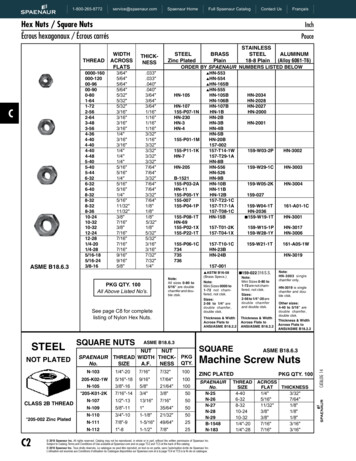
NCV7708FOvercurrent Detection Shut Down Control TimerThere are two protection mechanisms for output current,overcurrent and current limit.1. Current limit Always active with a typicalthreshold of 3 A.2. Overcurrent Detection Selectable shutdown timevia Bit 13 with a typical threshold of 1.45 A.Figure 6 shows the typical performance of a part whichhas exceeded the 1.45 A Overcurrent Detection thresholdand started the shutdown control timer. When Bit 13 1, theshutdown time is 25 msec. When Bit 13 0, the shutdowntime is 200 msec.(current limit)Once an Overcurrent Shutdown Delay Time event hasbeen detected by the NCV7708F, the timer setting cannot beinterrupted by an attempted change via a SPI command ofBit 13.Input Bit 13Overcurrent Shutdown Delay Time0200 msec125 msec3A(overcurrent) 1.45 AOUTx CurrentBit13 1(current limit)25 msec3A(overcurrent) 1.45 AOUTx CurrentBit13 0200 msecFigure 6. Output Current Shutdown Controlwww.onsemi.com13
NCV7708FUnder Load DetectionThe NCV7708F uses a global under load timer. An underload condition starts the global under load delay timer. Ifunder load occurs in another channel after the global timerhas been started, the delay for any subsequent under loadwill be the remainder of the initially started timer. The timerruns continuously with any persistent under load condition.The under load detect bit is reset by setting input data bit 0,SRR 1.The under load detection is accomplished by monitoringthe current from each output driver. A minimum load current(this is the maximum detection threshold) is required whenthe drivers are turned on. If the under load circuit detectionthreshold has been crossed for more than the under loaddelay time, the bit indicator (output bit #14) will be set to a1. In addition, the offending driver will be turned off only ifinput bit 14 (ULD) is set to 1 (true).UNDER LOAD DETECTION SHUT DOWNULD InputBit 14OUTx ULDConditionOutput Data Bit 14 UnderLoad Detect (ULD) StatusOUTx Status0000Unchanged11 (Need SRR to reset)Unchanged100Unchanged111 (Need SRR to reset)OUTx Latches Off (Need SRR to reset)Undervoltage Lockout (PSF)Undervoltage shutdown circuitry monitors the voltage onthe VS1 and VS2 pins. When the Undervoltage Thresholdlevel has been breached on both or either one of the VSxsupply inputs, output bit 15 (PSF) will be set and all outputswill turn off.Turn on/off status is maintained in the logic circuitry.When proper input voltage levels are re established, theprogrammed outputs will return to programmed operation.The Power Supply Fail bit is reset by setting input data bit0, SRR 1.UNDERVOLTAGE LOCK OUT (UVLO) SHUT DOWNVSx UVLOConditionOutput Data Bit 15 Power Supply Fail (PSF) StatusOUTx Status00Unchanged11 (Need SRR to reset)All Outputs Off (Remain off until VSx is out of UVLO)Overvoltage Shutdown (PSF)Overvoltage shutdown circuitry monitors the voltage onthe VS1 and VS2 pins. When the Overvoltage Thresholdvoltage level has been breached on both or either one of theVSx supply inputs, output bit 15 will be set and, if input bit15 (OVLO) is set to 1, all drivers will turn off. Turn on/offstatus is maintained in the logic circuitry. When proper inputvoltage levels are re established, the programmed outputswill turn back on. Overvoltage shutdown can be disabled byusing the SPI input bit 15 (OVLO 0). The Power SupplyFail bit is reset by setting input data bit 0, SRR 1.OVERVOLTAGE LOCK OUT (OVLO) SHUT DOWNOVLO Input Bit 15VSx OVLOConditionOutput Data Bit 15 PowerSupply Fail (PSF) StatusOUTx Status000Unchanged011 (Need SRR to reset)Unchanged100Unchanged111 (Need SRR to reset)All Outputs Latch Off while in OVLOReturn to programmed state out of OVLOwww.onsemi.com14
NCV7708FThermal ShutdownThermal warning information can be retrievedimmediately without performing a complete SPI accesscycle. Figure 7 displays how this is accomplished. Bringingthe CSB pin from a 1 to a 0 with SI 0 immediately displaysthe information on output data bit 0, thermal warning. As thetemperature of the NCV7708F changes from a conditionfrom below the thermal warning threshold to above thethermal warning threshold, the state of the SO pin changesand this level is available immediately when the CSB goesto 0. A 0 on SO indicates there is no thermal warning, whilea 1 indicates the IC is above the thermal warning threshold.This warning bit is reset by setting input data bit 0, SRR 1.Six independent thermal shutdown circuits are featured(one common sensor for each HS and LS transistor pair).Each sensor has two levels, one to give a Thermal Warning(TW) and a higher one, Thermal Shutdown, which will shutthe drivers off. When the part reaches the temperature pointof Thermal Warning, the output data bit 0 (TW) will be setto a 1, and the outputs will remain on. With one or moresensors detecting the thermal shutdown level, all channelswill be turned off simultaneously. All outputs will return tonormal operation when the part thermally recovers(Thermal toggling), because the thermal shutdown does notchange the channel selection. The output data bit 0, ThermalWarning, will latch and remain set, even after cooling, andis reset by using a software command to input bit 0 (SRR 1). Since thermal warning precedes a thermal shutdown,software polling of this bit will allow for load control andpossible prevention of thermal shutdown conditions.CSBCSBSCLKSCLKTWHSOSOTristate LevelTristate LevelNTWThermal Warning HighNo Thermal WarningFigure 7. Access to Temperature warning information shows the thermal information is available immediatelywith activation of the CSB signal without having to toggle the SCLK line.www.onsemi.com15
NCV7708FApplications DrawingThe applications drawing below displays the range withwhich this part can drive a multitude of loads.1. H Bridge Driver configuration2. Low Side Driver3. High Side DriverReverse battery diodeVBATVSxCINVSx3OUTHxOUTHxCEMC110 nF(optional)OUTLx12GNDGNDVSxCEMC310 nF(optional)OUTLxMCEMC410 nF(optional)OUTHxOUTLxGNDCEMC210 nF(optional)Figure 8. Application DrawingAny combination of H Bridge, high side, or low side drivers can be designed in. This allows for flexibility in manysystems.H Bridge Driver ConfigurationOvervoltage Clamping Driving Inductive LoadsThe NCV7708F has the flexibility of controlling eachdriver independently. When the device is set up in anH Bridge configuration, the software design has to take careof avoiding simultaneous activation of connected HS and LStransistors. Resulting high shoot through currents couldcause irreversible damage to the device.To avoid excessive voltages when driving inductive loadsin a single side mode (LS or HS switch, no freewheelingpath), the NCV7708F provides internal clamping diodes.Thus any load type can be driven without the requirement ofexternal freewheeling diodes. Due to high power dissipationduring clamping, the maximum energy capability of thedriver transistor has to be considered.www.onsemi.com16
NCV7708FTYPICAL OPERATING CHARACTERISTICS2.01.8 1.0VCC SLEEP CURRENT (mA)HIGH SIDE CURRENT (A) 1.2 0.8 0.6 0.4 0.2 0.5 1.0 1.5 2.01.21.00.80.60.40 50 30 10 2.5VCC 5.25 V1030507090110 130 150HIGH SIDE PIN VOLTAGE (V)TJ, TEMPERATURE ( C)Figure 9. High Side Negative Clamp Voltage vs.Reverse CurrentFigure 10. VCC Sleep Supply Current vs.Temperature452.0441.84342414039383736 50 30 10Iout 50 mA1030507090VS1 VS2 SLEEP CURRENT (mA)LOW SIDE CLAMPING VOLTAGE (V)01.40.2TA 25 C01.61.61.41.21.00.80.60.40.20 50 30 10110 130 1501030507090110 130 150TJ, TEMPERATURE ( C)TJ, TEMPERATURE ( C)Figure 11. Low Side Clamping Voltage vs.TemperatureFigure 12. VS1 VS2 Sleep Current vs.Temperaturewww.onsemi.com17
NCV7708FTable 1. FAULT HANDLINGDriver Condition afterParameters WithinSpecified LimitsOutput Register ClearRequirementOffending Driver islatched off after200 msecOffending Driver islatched offValid SPI frame with SRRset to 1LatchedOffending Driver islatched off byovercurrent timer after25 msecOffending Driver islatched offValid SPI frame with SRRset to 1Under Load(Input ULD Bit 14 0)LatchedUnchangedUnchangedValid SPI frame with SRRset to 1Under Load(Input ULD Bit 14 1)LatchedOffending Driver islatched off after350 msecOffending Driver islatched offValid SPI frame with SRRset to 1 falls belowPower Supply Fail(OVLO)LatchedOutput Driver onBit 15 0Outputs return to theirprevious programmedstatePS
A Assembly Location WL Wafer Lot YY Year WW Work Week G Pb Free Package MARKING DIAGRAMS SOIC 28 DW SUFFIX CASE 751F www.onsemi.com †For information on tape and reel specifications, including part orientation and tape sizes, please refer to our Tape and Reel Packaging Specifications Brochure, BRD8011/D. NCV7708F X AWLYYWWG