Transcription
EE 461Computer‐Communication NetworksPayman ArabshahiDepartment of Electrical Engineering1
Team Instructor: Payman Arabshahi, Dept. of ElectricalEngineering and Applied Physics Laboratory,payman@ee.washington.edu, Tel: (206) 221‐6990. Officehours: after class (EEB 025), or by appointment. Teaching Assistant: Arash Tarkhan,atarkahn@uw.edu, (206) 601‐8646. Office Hours:Mondays, 2:00‐3:30 pm in EEB M406, and Wednesdays,2:30‐4:00 pm in EEB M306, or by appointment.2
TimeClass Mondays and Wednesdays, 11:30 ‐ 01:20 pm (class ‐ EEB025)TA Sessions Mondays: 03:30 ‐ 04:20 (session AA ‐ EEB 054) Wednesdays: 01:30 ‐ 02:20 (session AB ‐ EEB 025)3
What is this course about?Introductory course in computer networking Learn principles of computer networking Learn practice of computer networking Internet architecture/protocols as case study by the time you are finished Goals: Learn a lot (not just factoids, but principles and practice) Have fun! (learn how to spoof mail, sniff network traffic,write cool network apps, and more)4
Where we were5
Where we are6
Course InformationIntroductory undergraduate course in computer networking Who is this course for? Undergrad EE students Prerequisites: Algorithms, operating systems, programming skills, probability andstatistics Course materials: Text: Computer Networking: A Top DownApproach, J. Kurose & K. Ross, Addison Wesley,6th ed., 2013. Class notes 7
Course Information Class web site:the most importantpiece of info you willreceive today!http://courses.washington.edu/ee461/ everything is posted on this site! syllabus TA info class notes (powerpoint, pdf) assignments nothing will be handed out in class :‐)8
Course Information Class mailing list: ee461a sp15@u.washington.edu Grading:Courseworkapprox amountwritten homeworks8lab assignments (Wireshark)8MidtermFinalapprox %10%10%40%40% All homeworks will be due in class or online, one week fromassigned date. No late homeworks will be accepted. There will be no make‐up exams; absences with validreasons will have credit pro‐rated to the Final. All exams are in‐class, closed‐book; two 8 1/2 x 11 sheets offormulas/notes allowed for Midterm and four sheets for theFinal.9
Course InformationOdds and ends me in‐class style: interaction, questions (please!) incomplete policy academic honesty getting into this course Software to use (Wireshark)questions, comments, ?10
Course OverviewPart 1: Introduction (1 class, text: Chapter 1) what is the Internet, What is a protocol? network edge, network core, network access physical media delay, loss in packet‐switched networks protocol layers, service models Internet backbones, NAPs and ISPs brief history of networking, Internet11
A Top‐Down ApproachWe’ll cover networkingtop‐down end‐system applications transport: TCP/UDP network core: routing,hooking nets together link‐level protocols, e.g.,Ethernet other stuff: security,mobility, management,12
Course OverviewPart 2: Application Layer (2 classes, text: Ch. 2) principles of application‐layer protocols World Wide Web: HTTP file transfer: FTP electronic mail in the Internet the Internet's directory service: DNS socket programming13
Course OverviewPart 3: Transport Layer (2 classes, text Ch. 3) Transport‐layer services and principles Multiplexing and demultiplexing applications Connectionless transport: UDP Principles of reliable of data transfer TCP case study Principles of congestion control TCP congestion controlMIDTERM EXAM(approx)14
Course OverviewPart 4: Network Layer (2 classes, text: Ch. 4) introduction and network service model what’s inside a router? routing principles (algorithms) hierarchical routing IP: the Internet Protocol Internet routing: RIP, OSPF, BGP15
Course OverviewPart 5: Link Layer, LANs (1.5 classes, text: Ch. 5) introduction, services error detection, correction multiple access protocols, LANs LAN addresses, ARP Ethernet PPP: the Point‐to‐Point protocol A network as a link layer: ATM, MPLS16
Course OverviewPart 6: Wireless and Mobile Networks (1 class, Ch. 6) wireless link characteristics the wireless link: 802.11 cellular Internet access mobility principles mobility in practice: mobile IP mobility in cellular networks17
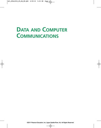
ISO/OSI Layered Communication Model
ISO/OSI Layered Communication Model Layered communication models are traditionally used for data communication.Layering is an example of a divide‐and‐conquer strategy: if the problemis too complicated, divide it into smaller and more manageable partsand solve each subproblem. Does not necessarily lead to the mostefficient solution.Each layer forms a model of the layers below and implement a serviceto the layer above. For instance, the physical layer deals withtransmitting bits from one node to another. The data link layer sees abit pipe, but not how the bit pipe is implemented with electronics,radio circuitry or optoelectronics.Each layer also communicates with its counterpart on another nodeover the virtual link provided by the layers below it.Each layer has a standard defined input and a standard defined output.
OSI Model Explained We look at a top‐down explanation of the OSI Model. It starts with the user's PC and it follows what happens to the user's file asit passes though the different OSI Model layers. We use this approach here to show how the user's files are transformed(through the layers) into a bit stream for transmission on the network. The keyboard and application are shown as inputs to the CPU (requestingaccess to the hard disk). The keyboard requests accesses through userinquiries (such as “dir" or “ls” commands) and the application seeksaccess through "File Openings" and "Saves". The CPU, through the DiskOperating System, sends and receives data from the local hard disk ("C:").Basic PC logical flowchart.
OSI Model Explained The Network Redirector is a Terminate and Stay Resident program: itpresents the network hard disk as another local hard disk ("G:") to the CPU. All CPU requests are intercepted by the "Network Redirector". It checks tosee if either a local or a network drive is requested. If a local drive is requested, the request is passed on to the DOS. However, if a network drive is requested, the request is then passed on tothe network operating system (NOS).Simple network redirection.
OSI Model Explained Email, client‐server databases, games played over the network, print andfile servers, remote logons, and network management programs (or any"network aware" applications) are all aware of the network redirector. They have the ability to communicate directly with other "networkapplications" on the network. The "Network Aware Applications" and the "Network Redirector" make upLayer 7 – the Application layer of the OSI Model.PC Workstation with network aware software.
OSI Model Explained The Network Redirector sends CPU operating system native code tothe network operating system. But the coding and format of the data is not recognizable by thenetwork operating system. The data consists of file transfers and network calls by networkaware programs. For example, when a dumb terminal is used as a workstation (in amainframe or minicomputer network), the network data is translatedinto (and from) the format that the terminal can use. Layer 6 – the Presentation layer presents data to and from theterminal using special control characters to control the screen display(LF‐line feed, CR‐carriage return, cursor movement, etc.). Thepresentation of data on the screen would depend on the type ofterminal that's used: VT100
OSI Model Explained The Presentation layer also strips the pertinent file from the workstationoperating system's file envelope. The control characters, screenformatting, and workstation operating system envelope are all stripped oradded to the file (if the workstation is receiving or transmitting data to thenetwork). The Presentation Layer also controls security at the file level: this providesboth file locking and user security. At this point, the data is contiguous and complete (i.e. one large data file).Presentation layer.
OSI Model Explained The Presentation layer relieves the Application layer of concernregarding syntactical differences in data representation within theend‐user systems. MIME encoding, encryption and similar manipulation of thepresentation of data is done at this layer. An example of a presentation service would be the conversion of aEBCDIC‐coded text file to an ASCII‐coded file.
OSI Model Explained Layer 5 – the Session layer manages the communications between the workstation and the network.It directs the information to the correct destination, and identifies thesource to the destination.It identifies the type of information as data or control.It manages the initial start‐up of a session, and the orderly closing of asession.The Session layer also manages Log on procedures and Passwordrecognition.Session layer.
OSI Model Explained The Session layer provides the mechanism for managing the dialoguebetween end‐user application processes. It provides for either duplex or half‐duplex operation and establishescheckpointing, adjournment, termination, and restart procedures. This layer is responsible for setting up and tearing down TCP/IPsessions.
OSI Model Explained In order for the data to be sent across the network, the file must be broken up into usable small data segments (typically 512 ‐ 18K bytes).Layer 4 – the Transport layer breaks up the file into segments fortransport to the network, and combines incoming segments into acontiguous file.The Transport layer does this logically, not physically, and it is done insoftware as opposed to hardware.The Transport layer provides error checking at the segment level (framecontrol sequence). This makes sure that the datagrams are in the correctorder: the Transport layer will correct out of order datagrams.The Transport layer guarantees an error‐free host to host connection. It isnot concerned with the path between machines.Transport layer.
OSI Model Explained The purpose of the Transport layer is to provide transparent transferof data between end users, thus relieving the upper layers from anyconcern with providing reliable and cost‐effective data transfer. The transport layer controls the reliability of a given link. Some protocols are stateful and connection oriented. This means thatthe session layer can keep track of the packets and retransmit thosethat fail. The best known example of a layer 4 protocol is TCP.
OSI Model Explained Layer 3 – the Network layer is concerned with the path through thenetwork. It is responsible for routing, switching, and controlling the flow ofinformation between hosts. The Network layer converts the segments into smaller datagrams than thenetwork can handle: network hardware source and destination addressesare also added. The Network layer does not guarantee that the datagram will reach itsdestination.Network layer.
OSI Model Explained The Network layer provides the functional and procedural means oftransferring variable length data sequences from a source to adestination via one or more networks while maintaining the quality ofservice requested by the Transport layer. The Network layer performs network routing, flow control,segmentation/de‐segmentation, and error control functions. The router operates at this layer – sending data throughout theextended network and making the Internet possible, although thereare layer 3 (or IP) switches.
OSI Model Explained Layer 2 – the Data Link layer is a firmware layer of the network interface card.It puts the datagrams into packets (frames of bits: 1s & 0s) fortransmission, and assembles received packets into datagrams.It works at the bit level, and adds start / stop flags and bit error checking(CRC or parity) to the packet frame.Error checking is at the bit level only: packets with errors are discardedand a request for re‐transmission is sent out.The Data Link layer is primarily concerned with bit sequence.Data Link layer.
OSI Model Explained The Data Link layer provides the functional and procedural means totransfer data between network entities and to detect and possibly correcterrors that may occur in the Physical layer. The addressing scheme is physical which means that the addresses arehard‐coded into the network cards at the time of manufacture. The best known example of this is Ethernet. Other examples of data link protocols are HDLC and ADCCP for point‐to‐point or packet‐switched networks and LLC and Aloha for local areanetworks. This is the layer at which bridges and switches operate. Connectivity is provided only among locally attached network nodes.
OSI Model Explained Layer 1 – the Physical layer concerns itself with the transmission of bits. It also manages the network card's hardware interface to the network. The hardware interface involves the type of cabling (coax, twisted pair,etc.), frequency of operation (1 Mbps, 10Mbps, etc.), voltage levels, cableterminations, topography (star, bus, ring, etc.), etc. Examples of Physical layer protocols are as follows: 10Base5 ‐ Thicknet,10Base2 ‐ Thinnet, 10BaseT ‐ twisted pair, ArcNet, FDDI, etc.Physical layer.
OSI Model Explained The physical layer defines all electrical and physical specifications fordevices. This includes the layout of pins, voltages, and cable specifications. Hubs and repeaters are physical‐layer devices. The major functions and services performed by the physical layer are: Establishment and termination of a connection to a communicationsmedium.Participation in the process whereby the communication resources areeffectively shared among multiple users. For example, contentionresolution and flow control.Modulation, or conversion between the representation of digital datain user equipment and the corresponding signals transmitted over acommunications channel. This is signals operating over the physicalcabling ‐ copper and fiber optic, for example. SCSI operates at this level.
OSI Model Explained Layer‐Specific Communication Each layer may add a Header and a Trailer to its Data (whichconsists of the next higher layer's Header, Trailer and Data as itmoves through the layers).The Headers contain information that specifically addresses layer‐to‐layer communication.For example, the Transport Header (TH) contains information thatonly the Transport layer sees. All other layers below the Transportlayer pass the Transport Header as part of their Data.
OSI Model ExplainedLayer‐specific communication.
OSI Model ExplainedOSI Model Functional Drawing.
OSI Model Explained The mnemonics "People Design Networks To Send PacketsAccurately", "Please Do Not Throw Sausage Pizza Away", and "AllPeople Seem To Need Data Processing" may help you remember thelayers. Real‐world protocol suites often do not strictly match the seven‐layermodel. There can be some argument as to where the distinctions betweenlayers are drawn; there is no one correct answer. However, most protocol suites share the concept of three generalsections: media, covering layers 1 and 2; transport, covering layers 3and 4, and application, covering layers 5 through 7. Strict conformance to the OSI model has not been a common goal inreal‐world networks, partly due to the negative view of the OSIprotocol suite.
OSI Model Explained Andrew Tanenbaum argues in his popular textbook Computer Networksthat the failure of the OSI suite to become popular was due to Bad timing – the model was finished only after a significant amount ofresearch time and money had been spent on the TCP/IP model. Bad technology, because the session and presentation layers arenearly empty, whereas the data link layer is overfull. Bad implementations, since early ones were notoriously buggy and inthe early days, OSI became synonymous with poor quality, whereasearly implementations of TCP/IP were more reliable. Bad politics, because TCP/IP was closely associated with Unix, makingit popular in academia, whereas OSI did not have this association. However the model is still the general reference standard for nearly allnetworking documentation. All networking phrases referring to numberedlayers, such as "layer 3 switching", refer to this OSI model.
OSI Model Explained The 7 layer model has often been extended in a humorous manner, torefer to non‐technical issues or problems. A common joke is the 9 layermodel, with layers 8 and 9 being the "financial" and "political" layers. Network technicians will sometimes refer euphemistically to "layer‐eightproblems," meaning problems with an end user and not with the network. Carl Malamud, in his book Stacks, defines layers 8, 9, and 10 as "Money","Politics", and "Religion". The "Religion layer" is used to describe non‐rational behavior and/or decision‐making that cannot be accounted forwithin the lower nine levels. (For example, a manager who insists onmigrating all systems to a Microsoft platform "because everyone else isdoing it" is said to be operating in Layer 10.) The OSI model has also sometimes been jokingly called the "Taco Bellmodel", since the restaurant chain has sometimes sold a 7 layer burrito.
James Bond Meets the 7 Layer OSI Model James Bond meets Number One on the 7th floor of the spy headquartersbuilding. Number One gives Bond a secret message that must get throughto the US Embassy across town. Bond proceeds to the 6th floor where the message is translated into anintermediary language, encrypted and miniaturized. Bond takes the elevator to the 5th floor where Security checks themessage to be sure it is all there and puts some checkpoints in themessage so his counterpart at the US end can be sure he’s got the wholemessage. On the 4th floor, the message is analyzed to see if it can be combined withsome other small messages that need to go to the US end. Also if themessage was very large it might be broken into several small packages soother spies can take it and have it reassembled on the other end.
James Bond Meets the 7 Layer OSI Model The 3rd floor personnel check the address on the message and determinewho the addressee is and advising Bond of the fastest route to theEmbassy. On the 2nd floor the message is put into a special courier pouch (packet).It contains the message, the sender and destination ID. It also warns therecipient if other pieces are still coming. Bond proceeds to the 1st floor where Q has prepared the Aston Martin forthe trip to the Embassy. Bond departs for the US Embassy with the secret packet in hand. On theother end the process is reversed. Bond proceeds from floor to floorwhere the message is decoded. The US Ambassador is very grateful the message got through ames.aspx
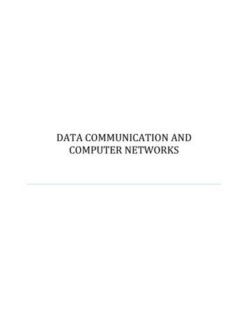
The Shannon ModelClaude Elwood Shannon ‐ 17 April 1961 (photograph by Göran Einarsson)44
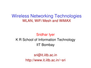
The Shannon Model Claude Shannon, 1916‐2001. His famous paper, “A Mathematical Theory of Communication”, waswritten in 1948.Basic elements of a digital communication system45
The Shannon ModelBasic elements of a digital communication system:Information rate: Rb 1/TbEnergy per bit: Eb PTbTransmitter/Receiver pair.
The Shannon Model The task of the receiver blocks is basically to undo the transmitter blocks. The demodulator decides which bits where most likely transmitted by thetransmitter. The channel decoder inspects the received bits to detect and correct errors. The source decoder formats the bit stream into a form suited to the sink. Inevitably, there will be errors in this process due to channel noise and distortion. The main performance measure is the bit error rate: the probability that areceived bit is not equal to the transmitted bit. It is the task of the channel encoder/decoder and modulator/demodulator toreduce the bit error probability to a level which is acceptable for the sourcedecoder and sink. Example: GSM bit error rate after demodulation is 0.1‐0.01,after channel decoding 0.001 (acceptable for speech communication; muchlower error rates usually required by data services).
The Shannon Model In the Shannon model of a one‐way digital communication link informationfrom the source is to be transmitted to the sink. The transmitter and receiver consist of three blocks each. The source emits bits at a certain rate Rs bits/s; the source encoder reducesthis bit rate by removing redundancy and unimportant information from thesource bit stream. Example: GSM Rs 64 kbps output rate 13 kbps. The channel encoder introduces parity bits (or redundancy) to enable thereceiver to detect and possibly correct errors that occur on the channel.Example: GSM channel encoder adds approximately one parity bit perinformation bit: output rate approximately 26 kbps. The modulator transforms the coded bits into waveforms suitable for thechannel. Example: GSM bits are (roughly) represented with sine waves ofdifferent frequencies: one frequency for a 0 bit and a different one for a 1bit. The channel typically distorts the transmitted signal and adds noise.
Finally What design principles to use? J.H. Saltzer, D.P. Reed, and D.D. Clark, "End‐To‐Endarguments in system design", ACM Transactions onComputer Systems, vol. 2, no. 4, Nov. 1984. B. Carpenter, RFC 1958, Architectural Principles of theInternet, 1996. D. Thaler and B. Aboba, RFC 5218, What Makes for aSuccessful Protocol? 2008.
Advice for building product, networks, life! Andrew Tanenbaum’s and David Wetherall’s adaption ofRFC 1958, in their classic text, Computer Networks. This synopsis can be taken in a more general sense andapplied to building successful products and even containssome life lessons
Advice for building product, networks, life!1. Make sure it works. Do not finalize the design or standard untilmultiple prototypes have successfully communicated with each other.All too often, designers first write a 1000‐page standard, get itapproved, then discover it is deeply flawed and does not work. Thenthey write version 1.1 of the standard. This is not the way to go.
Advice for building product, networks, life!2. Keep it simple. When in doubt, use the simplest solution. William ofOccam stated this principle (Occam’s razor) in the 14th century. Put inmodern terms: fight features. If a feature is not absolutely essential,leave it out, especially if the same effect can be achieved bycombining other features.
Advice for building product, networks, life!3. Make clear choices. If there are several ways of doing the same thing,choose one. Having two or more ways to do the same thing is lookingfor trouble. Standards often have multiple options or modes orparameters because several powerful parties insists that their way isbest. Designers should strongly resist this tendency. Just say no.
Advice for building product, networks, life!4. Exploit modularity. This principle leads directly to the idea of havingprotocol stacks, each of whole layers is independent of all the otherones. In this way, if circumstances require one module or layer to bechanged, the other ones will not be affected.
Advice for building product, networks, life!5. Expect heterogeneity. Different types of hardware, transmissionfacilities, and applications will occur on any large network. To handlethem, the network design must be simple, general, and flexible.
Advice for building product, networks, life!6. Avoid static options and parameters. If parameters are unavoidable(e.g., maximum packet size), it is best to have the sender and receivernegotiate a value rather than defining fixed choices.
Advice for building product, networks, life!7. Look for a good design; it need not be perfect. Often, the designershave a good design but it cannot handle some weird special case.Rather than messing up the design, the designers should go with thegood design and put the burden of working around it on the peoplewith the strange requirements.
Advice for building product, networks, life!7. Look for a good design; it need not be perfect. Often, the designershave a good design but it cannot handle some weird special case.Rather than messing up the design, the designers should go with thegood design and put the burden of working around it on the peoplewith the strange requirements.
Advice for building product, networks, life!8. Be strict when sending and tolerant when receiving. In other words,send only packets that rigorously comply with the standards, butexpect incoming packets that may not be fully conformant and try todeal with them.
Advice for building product, networks, life!9. Think about scalability. If the system is to handle millions of hostsand billions of users effectively, no centralized databases of any kindare tolerable and load must be spread as evenly as possible over theavailable resources.
Advice for building product, networks, life!10.Consider performance and cost. If a network has poor performanceor outrageous costs, nobody will use it.
End of course overview/* */ ?62
lab assignments (Wireshark) 8 10% Midterm 40% Final 40% Class mailing list:ee461a_sp15@u.washington.edu Grading: All homeworks will be due in class or online, one week from assigned date. No late homeworks will be accepted. There will be no make‐up exams; absences with valid