Transcription
—PRODUCT BROCHURECyberex SuperSwitch 4 technology200A–4000A (3-pole) 200A–800A (4-pole)digital static transfer switch
2C Y B E R E X S U P E R S W I T C H 4 D I G I TA L S TAT I C T R A N S F E R S W I TC H—SuperSwitch 4 technology200A–4000A (3-pole) 200A–800A (4-pole)Its standard ultra-dense design maximizes physicalfloor space. Front access is required for operationand removal of serviceable components, while oneside or rear access is required for installation andtightening of customer connections. A full frontaccess cabinet design is also available for completeoperation, maintenance, installation and IR scanningaccessibility.SuperSwitch 4 redefines reliabilityForty years ago, Cyberex revolutionized powerdistribution with its invention of the digital statictransfer switch (STS). Since then, building on theinnovation of ABB engineering and the technologicaladvancements and commissioning of the mostextensive installed base of STSs worldwide, theSuperSwitch 4 has evolved. Designed with a ‘true’fault-tolerant architecture, SuperSwitch 4 ensuresthere is truly no single point of failure through theuse of our patented transfer algorithms and robustelectrical components. With an increased MTBDEto an estimated 1.5 million hours, SuperSwitch 4reliability is unmatched. SuperSwitch 4 redefinespower reliability with its exceptional design,serviceability and user-interface.Reliability through design excellenceThe Cyberex brand has been an industry leader inthe design and development of mission criticalsystems that ensure uptime and businesscontinuity for customers across the globe. Werecognize that every customer has unique electricalrequirements and we work closely with them todevelop solutions that solve their most difficultchallenges.Fully rated hockey puck SCRs are employed toprevent system damage after load faults. Thesuperior cooling design of the assembly enableshigher current applications. Infrared scans are easilyaccomplished without removal of assembly.Connections and maintenance are made easier bystaggered phase connections and ample gutterspace. 100% of connections are torqued ensuringmaximum reliability.State of the art performance E xpands SuperSwitch technology with enhancedplatform and features 1 0.4" color TFT industrial use LED touchscreen GUI 2 5% faster transfer times 4 0% lower inrush limiting E nhanced power quality detection F ield calibration support U SB port for software upgrades; data and eventdownloads 1 6 user configurable alarm relays 10 user inputs for communications control E nhanced meters and trending 10 cycle waveshape captures of critical powerevents I mproved circuit redundancySuperSwitch 4 provides maximum reliabilitythrough its innovative design. The modularcomponents, from the power stage to theredundant bus architecture, have been engineeredto unprecedented standards.The SuperSwitch 4 is available in select cabinetsizes that cater to your serviceability requirements.Front access cabinetFront and side access cabinet
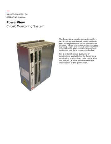
3—SuperSwitch 4 key applicationsEngineered to protect critical loadsThe SuperSwitch 4 is the cornerstone of redundantpower for a wide range of applications includingdata centers, hospitals, semiconductormanufacturing and other installations wherecontinuous power is critical to a facility’s mission.Engineered to protect critical loads in bothcommercial and industrial environments, theseswitches can transfer power between any twosources of power, including any combination ofutility, UPS and generators.Primary switching architectureStatic Transfer Switches (STSs) are centralcomponents in data center power systemconfigurations. The typical system designincorporates two separate uninterruptible powersupplies (UPSs), Source 1 and Source 2 feeding thepreferred and alternate sources of the STS. Thesedevices are the bridge between the power sourcesUPSs and the power distribution units (PDUs) wherea transformer is needed to typically switch the 480Vside (primary) to the 208V side (secondary). Theprimary side switching (480V) is the most commonand cost effective architecture to the customer interms of smaller footprint and lower costs becauseonly one transformer is needed. The alternativearchitecture would be to switch the secondarywhich would require each source to have its ownfully rated transformer (208V).Data center: Mission critical facilities used tohouse computer, network, data storage,telecommunications, and other vital systems thatrequire constant power with no interruptions.Hospitals: Health care institutions that requireconstant power with no interruptions to data andrecords management.Manufacturing/business operations:Manufacturing and business operations thatrequire constant power without interruptions dueto the critical nature of their vital IT functions.Flexible system architecture ready: N 1, 2N, 2N 1, N N, 3N/2, and catcher systems. ABB catcher systemconfigurations allow redundancy and reliability and improve total costs of ownership.—The SuperSwitch 4 ispart of ABB’s broadrange of products andintegrated solutionsthat ensure datacenters operate withoptimum reliability andefficiency. From powerdistribution units tostatic transfer switchesand uninterruptiblepower supply systems,ABB can optimize yourcentralized powerprotection design.UPS 1UPS 2UPS 3STSSTSSTSPDUPDUPDUCatcher UPS
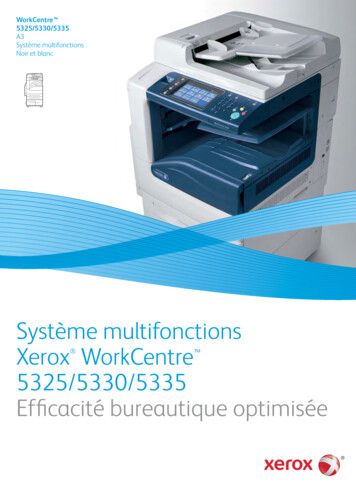
4C Y B E R E X S U P E R S W I T C H 4 D I G I TA L S TAT I C T R A N S F E R S W I TC H—Dynamic inrush restraint for applicationswith downstream transformersInrush currents degrade power qualityStatic Transfer Switches (STSs) are essentialcomponents in data center power systemconfigurations. Mainly relying on transformersprimary side switching, these devices are thebridge between the power sources and the powerdistribution units. This architecture offers manyadvantages to the customer in terms of smallerfootprint and lower costs; however, if not properlyswitched, high transient inrush in downstreamtransformers will occur.The inrush currents produced degrade the powerquality of the preferred source, overload upstreamUPSs and trip protective circuit breakers. Theinrush currents can also create intolerable forces inthe windings, which in turn reduce the lifecycle ofpower transformers as these currents can reachthe short circuit rated value and can last manycycles before they dissipate.Real Time Flux Control for DIRWith state of the art digital signal processors and anewly developed algorithm, an innovative approachwas created called Real Time Flux Control fordynamic inrush restraint (DIR.) Using advancedReal Time Flux Control, SuperSwitch 4 candynamically monitor and adapt its transferswitching to account for any variation or conditionthat may occur during an upstream outage. RealTime Flux Control enables out of phase transfertimes that are 25% faster and inrush currents thatare 40% lower than previous generation systems.By controlling inrush currents, the SuperSwitch 4protects upstream and downstream infrastructurefrom the harmful effects of excessive currents.How does it work?The STS constantly monitors the power quality ofboth sources taking into account the customerspecified thresholds. In addition, three transfermodes are available to customers to choose from:A9, DIR always and DIR limited.A9: this mode is a proprietary method that is to beused only when the phase difference between thesources is less than a user defined phase angle.The range of this setting is adjustable up to /– 30degrees, and is not recommended for larger phasedifferences.DIR always: this mode allows the SuperSwitch 4 topermanently transfer using the Real Time FluxControl approach and should result in low inrushregardless of how far the two sources are out ofphase.DIR limited: this mode is the recommended settingfor the SuperSwitch 4. In this mode, a hybridapproach of A9 and DIR is performed depending onthe phase difference between the sources.Most customers use the recommended setting ofDIR limited because the STS will auto select when,and if, the DIR function is needed depending on thephase difference as illustrated by Figure 1 below.Outside user definedphase window:Transfer Mode DIR180 degreeThis technology is an intelligent proprietarymethod that makes no compromise to the voltageoutput for mission critical applications byproviding a performance that exceeds the CBEMAand ITIC standards, regardless of phase driftbetween sources.—Figure 1: DIR limited vs phase angleInside userdefinedphasewindow:Transfer ModeA90 degree
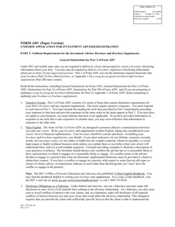
5—Best solution: A real time switching methodHow does it perform?The Real Time Flux Control is the optimalsolution for inrush reduction, it cleanlydisconnects the failing source and transfers thecritical load to a more reliable power qualitysource. Figures 2 and 3 show an out of phaseemergency transfer done on a 480 volt, 600 ampSTS feeding our 225kVA PDU transformer, the twosources were 60 degrees and 180 degreesrespectfully, and the transfer mode selected wasthe recommended “DIR limited.” The outage timewas measured to be 5.50 millisecond in the firstcase and 11.30 milliseconds in the second with noinrush observed.—Figure 2:Phase: 60 degreeOutage Time: 5.50 msCondition: Loss ofSource 1—Figure 3:Phase: 180 degreeOutage Time: 11.30 msCondition: ManualTransfer—Figure 4: 60Hz data for critical loads meeting CBEMA/ITIC curves.An intelligent method for Dynamic InrushRestraint M akes secondary switching (one PDUtransformer) reliable. E liminates the need for complex inverter controlschemes. M aintains true independence between UPSsystems (higher reliability). K eeps inrush value lower than 1.2x. E xceeds the ITIC and CBEMA curves standardsfor critical loads, see figure 4 above. S moothly transfers the load without creatingunnecessary voltage discontinuity anddisturbances to the load.
6C Y B E R E X S U P E R S W I T C H 4 D I G I TA L S TAT I C T R A N S F E R S W I TC H—Expert power managementThe SuperSwitch 4 harnesses the power of touch with an innovative user interfacethat utilizes a 10.4" color TFT industrial use VGA LED touchscreen GUI for self-guided,serviceability with minimal engagement, and the latest communication protocols.The monitor module delivers best-in-class, high-resolution display of color images.With ever-increasing power requirements andthe necessity to ensure uptime, SuperSwitch 4provides exceptional power management featuressuch as:Waveform captureSuperSwitch 4 is available with waveform capture.The waveform capture feature uses digital signalprocessors and high speed analog to digitalconverters to simultaneously sample sources andoutput voltages and currents. The waveform datais collected every 0.1 millisecond intervals as 12 bitsamples to provide an extremely high level ofaccuracy.The SuperSwitch 4 is capable of storing 20waveform capture events for both transfer andnon-transfer events. Each measurement containsa total of 10 cycles; 5 cycles prior to the event and5 cycles after the event. The waveform can bedownloaded as an image file from the display USBport for additional viewing and analysis.Software-guided breaker operation and bypassEasy to follow commands and indicator lightseliminate the causes of human error.Data and alarm managementWith over 100 warnings/alarms types, 5000 eventscan be stored or downloaded to a USB device foranalysis.Remote accessCompatibility with building management systemsprovides access from any location at any time.User-friendly control on all SS4 systems provide quick systemconfiguration, power monitoring and response to alarms
7—3-pole and 4-pole offerings3-pole offeringsAmp ratings200A, 250A, 400A 600AVoltage ratings208V, 380V, 400V, 208V, 380V, 400V, 208V, 380V, 400V, 480V415V, 480V, 600V 415V, 480V, 600V 415V, 480V, 600VFrequency ratings 60Hz, 50Hz800A, 1000A,1200A1600A2000A3000A4000A480V480V480V60Hz, 50Hz60Hz, 50Hz60Hz60Hz60Hz60HzSCCR ratings1100kAIC100kAIC65kAIC65kAIC, 100kAIC100kAIC65kAIC, 100kAIC100kAICCable BottomTop/BottomTop/BottomCable ottomTop/BottomTop/BottomInstallation andservice accessFront onlyFront andone side or rearFront andone side or rearFront onlyFront and rearFront onlyFront onlyDimensions(WxDxH)48" x 34" x 78"34" x 34" x 78"46" x 34" x 78"90" x 36" x 90"120" x 60" x 77"180" x 36" x 90"180" x 36" x 90"12Contact factory for 600V SCCRs.If cable Entry and Exit are from opposite sides (e.g. Bottom Entry and Top Exit), please consult with factory.SCR-based neutral switchingThe Cyberex SuperSwitch 4 offering has expanded to include models for 4-pole applications requiring switching of theneutral. For installations with separately derived systems, the SuperSwitch 4 minimizes the potential for circulatingneutral currents through the use of solid state switching technology.4-pole offeringsAmp ratings200A, 400A600A, 800AVoltage208V, 380V,400V, 415V208V, 380V,400V, 415VFrequency60Hz60HzSCCR100kAIC65kAICCable entry1Top/BottomTop/BottomCable exit1Top/BottomTop/BottomInstallation andservice accessFront andright side or rearFront andright side or rearDimensions(WxDxH)46" x 34" x 78"60" x 34" x 78"1If cable Entry and Exit are from opposite sides (e.g. Bottom Entry and Top Exit), please consult with factory.
8C Y B E R E X S U P E R S W I T C H 4 D I G I TA L S TAT I C T R A N S F E R S W I TC H—Technical specifications 200A–4000A (3-pole)ComponentsElectrical characteristicsPower semiconductors1Hockey puck type, type II fuseless designAmp ratings2User interface10.4" color TFT industrial use VGA LEDtouchscreen GUI200A, 250A, 400A, 600A, 800A, 1000A,1200A, 1600A, 2000A, 3000A, 4000AVoltage ratings208V, 380V, 400V, 415V, 480V, 600VCooling200A/250A – Convection cooled 400A – Redundant fansSCCR ratings365kAIC, 100kAICFrequency ratings460Hz, 50HzPower suppliesRedundantOverload capabilitySurge protectionSPD on each source125% for 30 min, 150% for 1 min, 200% for10 sec, 1000% for 3 cycles, 1500% for 1 cycleControl logicNo single point of failureOperational characteristicsOutput load switchesRedundantFull load efficiencyUp to 99.4% (480V), 98.7% (208V)Power wire and bus barCopperBypassSystem guidedProtectionUL 489 Molded Case Switches / 1200AUL 1066 Non-Automatic Switches 1600A, 3000A, 4000AUL 489 Insulated Case Switches 2000ASense transfer time(In phase) 4ms patented A9 transfer methodSense transfer time(out of phase) 15ms patented Real Time Flux Control methodCommunications and software16 form “C” relaysDownstream transformerinrush5 1.2x nominal transformer ratingAlarm relaysBuilding alarm inputs10 dry contact inputsOperating temperature0 to 40 CEPOLocal or remoteStorage temperature0 to 80 CModbusRTU over RS485, TCP over EthernetMTBDE1.5 million hoursService portAccessible without opening doors or panelsStandardsEvent alarm log5000 eventsSafetyETL listed to UL 1008ScETL listed to CAN/CSA-22.2 No. 1782ms, PLL detection per phaseEMCFCC compliant (part 15)Each source and output. True RMS,up to 13th harmonicEnclosureNEMA 1Power quality and meteringLoss of source detectionVoltageCurrentEach source and output. True RMS,up to 13th harmonicPeak current detectionEach source, resettableSource reacquisition3 cycles3000A and 4000A models are hybrid Type I and Type III.Units rated 1600A or higher available in 480V only.3Contact factory for 600V SCCRs.4600A in 50Hz is not available.5Based on DIR transfer.12
9Standard cabinet (3-Pole)Amps200250400600 4800100012001600200030004000VoltageSCCR 1Heat OutputCable entry2Cable exit 2Installation andservice access3Dim. Front only48"W x 34"D x 78"H32500.951124380100Top/BottomTop/BottomFront only48"W x 34"D x 78"H32500.951124400100Top/BottomTop/BottomFront only48"W x 34"D x 78"H32500.951124415100Top/BottomTop/BottomFront only48"W x 34"D x 78"H32500.951124480100Top/BottomTop/BottomFront only48"W x 34"D x 78"H32500.951124600100Top/BottomTop/BottomFront only48"W x 34"D x 78"H32500.951124208100Top/BottomTop/BottomFront only48"W x 34"D x 78"H46501.361124380100Top/BottomTop/BottomFront only48"W x 34"D x 78"H46501.361124400100Top/BottomTop/BottomFront only48"W x 34"D x 78"H46501.361124415100Top/BottomTop/BottomFront only48"W x 34"D x 78"H46501.361124480100Top/BottomTop/BottomFront only48"W x 34"D x 78"H46501.361124600100Top/BottomTop/BottomFront only48"W x 34"D x 78"H46501.361124208100Top/BottomTop/BottomFront only48"W x 34"D x 78"H90282.651179380100Top/BottomTop/BottomFront only48"W x 34"D x 78"H90282.651179400100Top/BottomTop/BottomFront only48"W x 34"D x 78"H90282.651179415100Top/BottomTop/BottomFront only48"W x 34"D x 78"H90282.651179480100Top/BottomTop/BottomFront only48"W x 34"D x 78"H90282.651179600100Top/BottomTop/BottomFront only48"W x 34"D x 78"H90282.651179208100Top/BottomTop/BottomFront and one side or rear34"W x 34"D x 78"H92002.701100380100Top/BottomTop/BottomFront and one side or rear34"W x 34"D x 78"H92002.701100400100Top/BottomTop/BottomFront and one side or rear34"W x 34"D x 78"H92002.701100415100Top/BottomTop/BottomFront and one side or rear34"W x 34"D x 78"H92002.701100480100Top/BottomTop/BottomFront and one side or rear34"W x 34"D x 78"H92002.701100600100Top/BottomTop/BottomFront and one side or rear34"W x 34"D x 78"H92002.70110020865Top/BottomTop/BottomFront and one side or rear46"W x 34"D x 78"H122503.60160038065Top/BottomTop/BottomFront and one side or rear46"W x 34"D x 78"H122503.60160040065Top/BottomTop/BottomFront and one side or rear46"W x 34"D x 78"H122503.60160041565Top/BottomTop/BottomFront and one side or rear46"W x 34"D x 78"H122503.60160048065Top/BottomTop/BottomFront and one side or rear46"W x 34"D x 78"H122503.60160060065Top/BottomTop/BottomFront and one side or rear46"W x 34"D x 78"H122503.60160020865Top/BottomTop/BottomFront and one side or rear46"W x 34"D x 78"H153004.50170038065Top/BottomTop/BottomFront and one side or rear46"W x 34"D x 78"H153004.50170040065Top/BottomTop/BottomFront and one side or rear46"W x 34"D x 78"H153004.50170041565Top/BottomTop/BottomFront and one side or rear46"W x 34"D x 78"H153004.50170048065Top/BottomTop/BottomFront and one side or rear46"W x 34"D x 78"H153004.50170060065Top/BottomTop/BottomFront and one side or rear46"W x 34"D x 78"H153004.50170020865Top/BottomTop/BottomFront and one side or rear46"W x 34"D x 78"H229006.70175038065Top/BottomTop/BottomFront and one side or rear46"W x 34"D x 78"H229006.70175040065Top/BottomTop/BottomFront and one side or rear46"W x 34"D x 78"H229006.70175041565Top/BottomTop/BottomFront and one side or rear46"W x 34"D x t and one side or rear46"W x 34"D x 78"H229006.7060065Top/BottomTop/BottomFront and one side or rear46"W x 34"D x 78"H229006.70175048065Top/BottomTop/BottomFront only90"W x 36"D x 90"H1530011.754975480100Top/BottomTop/BottomFront only90"W x 36"D x 90"H1530011.754975480100Top/BottomTop/BottomFront and Rear120"W x 60"D x 77"H2290018.75656048065Top/BottomTop/BottomFront only180"W x 36"D x 90"H*** consult factory ***480100Top/BottomTop/BottomFront only180"W x 36"D x 90"H*** consult factory ***480100Top/BottomTop/BottomFront only180"W x 36"D x 90"H*** consult factory ***Contact factory for 600V SCCRs.2If cable Entry and Exit are from opposite sides (e.g. Bottom Entry and Top Exit), please consult with factory.350Hz, 800A–1200A models only available with left side or rear access.4600A in 50Hz is not available.1BTU/HrFull Load
10C Y B E R E X S U P E R S W I T C H 4 D I G I TA L S TAT I C T R A N S F E R S W I TC H—Technical specifications 200A–800A (4-pole)ComponentsElectrical characteristicsPower semiconductorsHockey puck type, type II fuseless designAmp ratings200A, 400A, 600A, 800AUser interface10.4" color TFT industrial use VGA LEDtouchscreen GUIVoltage ratings208V, 380V, 400V, 415VSCCR ratings65kAIC, 100kAICRedundant fans with hall effect failuresensingFrequency60HzOverload capability125% for 30 min, 150% for 1 min, 200% for10 sec, 1000% for 3 cycles, 1500% for 1 cycleCoolingPower suppliesRedundantSurge protectionSPD on each sourceOperational characteristicsControl logicNo single point of failureFull load efficiencyUp to 99.4% (415V), 98.7% (208V)Output load switchesRedundantBypassSystem guidedPower wire and bus barCopper 4ms patented A9 transfer methodProtectionUL 489 Molded Case SwitchesSense transfer time(In phase)Sense transfer time(out of phase) 15ms patented Real Time Flux Control methodDownstream transformerinrush1 1.2x nominal transformer ratingOperating temperature0 to 40 CStorage temperature0 to 80 CMTBDE1.5 million hoursCommunications and softwareAlarm relays16 form “C” relaysBuilding alarm inputs10 dry contact inputsEPOLocal or remoteModbusRTU over RS485, TCP over EthernetService portAccessible without opening doors or panelsEvent alarm log5000 eventsPower quality and meteringLoss of source detection2ms, PLL detection per phaseVoltageEach source and output. True RMS,up to 13th harmonicCurrentEach source and output. True RMS,up to 13th harmonicPeak current detectionEach source, resettableSource reacquisition3 cyclesStandardsSafetyETL listed to UL 1008ScETL listed to CAN/CSA-22.2 No. 178EMCFCC compliant (part 15)EnclosureNEMA 11Based on DIR transfer.
11Standard cabinet (4-Pole)Amps2004006008001VoltageSCCRHeat OutputCable entry 1Cable exit1Installation andservice accessDim. (WxDxH)BTU/HrFull mFront and right side or rear46"W x 34"D x t and right side or rear46"W x 34"D x t and right side or rear46"W x 34"D x t and right side or rear46"W x 34"D x t and right side or rear46"W x 34"D x t and right side or rear46"W x 34"D x t and right side or rear46"W x 34"D x t and right side or rear46"W x 34"D x 78"H90282.65117920865kAICTop/BottomTop/BottomFront and right side or rear60"W x 34"D x 78"H92002.70110038065kAICTop/BottomTop/BottomFront and right side or rear60"W x 34"D x 78"H92002.70110040065kAICTop/BottomTop/BottomFront and right side or rear60"W x 34"D x 78"H92002.70110041565kAICTop/BottomTop/BottomFront and right side or rear60"W x 34"D x 78"H92002.70110020865kAICTop/BottomTop/BottomFront and right side or rear60"W x 34"D x t and right side or rear60"W x 34"D x t and right side or rear60"W x 34"D x t and right side or rear60"W x 34"D x 78"H122503.601600If cable Entry and Exit are from opposite sides (e.g. Bottom Entry and Top Exit), please consult with factory.
12C Y B E R E X S U P E R S W I T C H 4 D I G I TA L S TAT I C T R A N S F E R S W I TC H—ABB Inc.5900 Eastport BoulevardRichmond, VA 23231-4453 USATel: 1 800 292 3739Fax: 1 804 236 4047 Copyright 2020 ABB Inc. All rights reserved.Specifications subject to change without notice.E00BRO-STS-MK-0073Additional informationWe reserve the right to make technicalchanges to the product and to theinformation in this document withoutnotice. The agreed conditions at the timeof the order shall apply. ABB assumes noresponsibility for any errors or omissionsthat may appear in this document. Wereserve all rights in this document and inthe information contained therein.Without prior written approval from ABB,reproduction, disclosure to third partiesor use of any information, in whole or inpart, is strictly forbidden.082520abb.com
Forty years ago, Cyberex revolutionized power distribution with its invention of the digital static transfer switch (STS). Since then, building on the innovation of ABB engineering and the technological advancements and commissioning of the most extensive installed base of STSs worldwide, the SuperSwitch 4 has evolved. Designed with a 'true'