Transcription
Multibody System Dynamics 6: 123–142, 2001. 2001 Kluwer Academic Publishers. Printed in the Netherlands.123A Motorcycle Model for Stability andControl AnalysisROBIN S. SHARPSchool of Mechanical Engineering, Cranfield University, Whittle Building, Bedford MK43 0AL,U.K.DAVID J.N. LIMEBEERDepartment of Electrical and Electronic Engineering, Imperial College of Science, Technology andMedicine, Exhibition Road, London SW7 2BY, U.K.(Received: 8 November 1999; accepted in revised form: 27 April 2000)Abstract. The observed dynamic behaviour of motorcycles suggests that interesting and significantmotions occur that are not currently understood. The most elaborate modelling exercise completedso far has produced results that need confirmation and extension. The construction of these modelsnecessitates the use of automated methods and one such modelling methodology is described. Theautomated model building platform that was used here is AutoSim. This code was used to generatea variety of linear and nonlinear models in symbolic form. The relatively complex geometry of thesteering system and the front tyre force system is discussed in detail and a new method of checkingthe self-consistency of the model is described and exploited. Sample results in the form of root-locusplots for small perturbations from straight running and cornering equilibrium states are presented.These are used to reproduce important findings from the literature. Conclusions are drawn on thebasis of the results presented.Key words: motorcycle, stability, control, dynamics.1. IntroductionMotorcycles have several interesting dynamic properties, some of which are already well understood. For example, anybody who has ridden a bicycle will realisethat above a certain low speed, the unstable roll (or capsize) instability disappears as the speed increases. Once this stable speed has been reached, the machinethen displays lightly-damped oscillatory behaviours that are well understood inthe straight running case. The modes of oscillation are commonly called wobbleand weave and may be initiated by even small perturbations from straight running[1–3]. These motions are only a relatively simple subset of the general machinemotions. There is growing evidence to suggest that more general motions are ofinterest from rider safety and machine design points of view.The linear theory of the small perturbation motions near to straight running iswell developed [1] and quite well validated by experiments [4–12]. The essentialingredients of the theory are: (a) separate bodies for the front and rear frame that
124R.S. SHARP AND D.J.N. LIMEBEERare joined via an inclined steering head; (b) spinning road wheels; (c) lateral translation, yaw and roll freedoms of the rear frame; (d) twist and steer freedoms of thefront frame relative to the rear frame; (e) a fairly elaborate steady-state tyre forceand moment system representation that may well be empirical in nature; (f) the lagmechanisms by which tyre forces are delayed with respect to the slip phenomenathat produce them; (g) some aerodynamic effects, mainly so that tyre loads canbe properly adjusted as the motorcycle speed alters; and (h) some freedom for therider’s upper body to roll relative to the rear frame of the vehicle. The motions ofmajor interest occur at substantially constant speed, so that the forward speed ofthe machine and the spin velocities of the road wheels may be constrained. Whenthe tyres are rolling without significant longitudinal slip, the tyre force system issomewhat simplified, as compared with the completely general case.As compared with the straight running case, there are more complex motionsassociated with small perturbations from an equilibrium cornering condition. Inthe cornering case, the motorcycle’s forward speed, yaw rate, lateral accelerationand lean angle must be held at constant values. It should be noted that the geometry of the machine, the tyre force system and the aerodynamic forces all changewith the lean angle. Also, what were previously decoupled lateral and vertical motions now become interactive. It therefore becomes essential to include main framebounce, pitch and suspension freedoms in addition to the modelling ingredientslisted above. The coupling of the in-plane and out-of-plane motions was discussedby Jennings [13] and shown in detail by Koenen [14], whose work demonstratedthe analytical complexity of the theory at this level. We believe that this type ofcornering study is at the limit of practicality for hand analysis methods. Despiteone’s best efforts to eliminate errors, the detailed accuracy of this kind of modelis bound to remain suspect. The symbolic multi-body software system, AutoSim[15], has been applied recently to the general motorcycle cornering problem byGani [16]. A small part of his achievement was the accurate recreation of the handderived results of Sharp [2]. This model is a fore-runner of the present model.Advancing from the above small perturbation scenario, large geometry motionsand forcing from road irregularities, which causes time variation of parameter values, demand the inclusion of non-linear terms in the equations of motion. Thesystem dynamics contain new possibilities and there is mounting evidence frommachine usage that these issues require serious study. In the sequel we describe thesetting up of a model for the general motion of a motorcycle, using AutoSim [15].The use of the model to find the trim cornering states and the linearised equationsof motion for small perturbations about those states is described. Most of the results included are intended for direct comparison with the corresponding studiesin [14]. This work may promote changes in design methods for high-performancemotorcycles. Some brief discussion of the full non-linear and time varying problemwith road profile forcing is included but a detailed study of these issues is for thefuture.
A MOTORCYCLE MODEL FOR STABILITY AND CONTROL ANALYSIS1252. Fundamentals of AutoSimAutoSim [15] is a language used to derive the equations of motion of general multibody systems and is based on the object oriented language LISP [17]. The syntacticrules of AutoSim are straightforward. The output from AutoSim takes one of several forms: (a) a Rich Text Format file containing the symbolic equations of motionof the system described; (b) a ‘C’ or ‘FORTRAN’ language simulation programwith appropriate data files containing parameter values and simulation run controlparameters; or (c) linear state-space equations in a MATLAB ‘M-file’ format [18,19]. It should be noted that AutoSim’s linearisation of the non-linear equations ofmotion is symbolic and completely general. It is possible to determine the nonlinear steady turning equilibrium state and all the parameters required to describefully a small perturbation dynamics problem. The multi-body basis of AutoSimis Kane’s equations [20], an expression of the virtual power or Jourdain principle[21], which deals equally easily with holonomic and non-holonomic constraints.The simulation programs written by AutoSim contain many software engineeringfeatures which help to reduce execution times.On occasions AutoSim expressions are used to explain the motorcycle modelling theory and so it is important for the reader to pay some attention to the AutoSim programming language itself. At the core of the language are commands likeadd-body, add-point, add-speed-constraint, add-line-force, add-strut, add-moment,no-movement, etc., which, to some extent, are self-explanatory. Such commandscontain argument lists that are required to make their meaning precise. An AutoSimprogram begins by defining an inertial reference frame n, with fixed origin, n0, andfixed vector directions [nx], [ny] and [nz]. As new bodies are added, havingfreedoms relative to n, local origins and axes are employed. All the reference axissystems introduced are right-handed Cartesian sets and inertias are normally referenced to axes parallel to these through the material body’s mass centre. AutoSimcan transform from local co-ordinates to global ones and vice-versa. Specifically,points specified globally are conveniently used to define points in bodies. Thebody-fixed points coincide with the corresponding global points, fixed in n, whenthe system is in its nominal configuration.There are several commands for defining and manipulating vectors. For example, pos(p1,p2) defines a vector that points from p2 to p1; dot(vel(p1),[nz])is the component of the absolute velocity of p1 in the direction [nz];dir(pos(p1,p2)) is a unit vector in the direction p2 to p1; dplane([rwy],[nz])is the projection of [rwy] onto the plane normal to [nz]; and cross(a,b) is thevector product of a and b. In each case, the square brackets indicate a unit vectoralong a (Cartesian) body axis. The ‘setsym’ command is used to define a newsymbol, such a symbol being identified by the ‘@’ character.At the head of an AutoSim program are some commands that are used to resetthe system, define the gravitational field, select the unit system to be employed,specify the simulation language in which the code written by AutoSim is to be
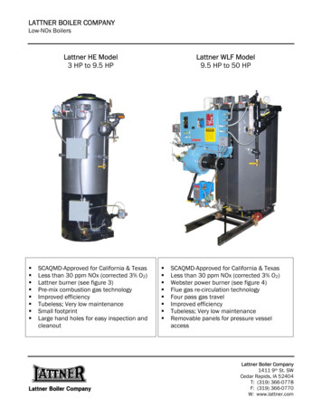
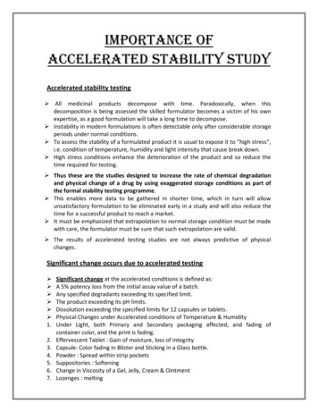
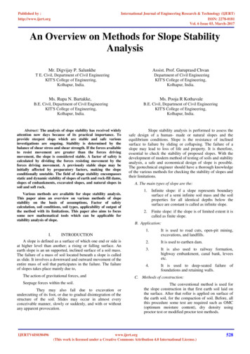
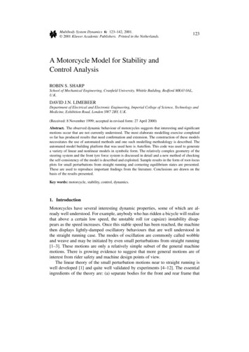
126R.S. SHARP AND D.J.N. LIMEBEERFigure 1. Motorcycle model in its nominal state with the key points labelled.generated, select the type of numerical integrator to be installed in the code and tocontrol the symbolic manipulations in various other ways. When the analyst doesnot exercise choice overtly in these matters, AutoSim uses default settings from aconfiguration file that the analyst is free to access.3. Modelling the MotorcycleThe important parts of the motorcycle model are shown in Figure 1. The geometrydepicted here is that for the nominal configuration in static equilibrium and the keypoints of the model are labelled. Prior work [6, 14, 22, 23] has shown that the compliance of the rear frame is important, because it impacts on the dynamic propertiesof the front frame via the boundary conditions. Other sources of compliance in theframe are known to be less important [24] and are consequently ignored here.The multi-body structure and the relative freedoms between the bodies areshown in Figure 2. For completely general motions of the motorcycle, the wheelspin freedoms would be left unconstrained with the rotations determined by a tyreforce model. In this study we concentrate on a more constrained set of possibilities in which the longitudinal tyre forces are relatively small and the accelerationor deceleration of the machine is modest. In these circumstances, the lateral andlongitudinal tyre force system interactions are small and can be neglected. In thiscase an overt longitudinal tyre force description can be avoided by constrainingthe wheels to rotate without longitudinal slip. The effect of such constraints is toinclude in the calculations the gyroscopic torques due to the spinning wheels.Due to the geometrical complexity in the region of the front tyre to groundcontact, which is further discussed in Section 3.1 and to which the kinematicanalysis of the Appendix relates, a precise description of the no-slip condition atthe front wheel leads to complex symbolic expressions, which AutoSim [15] willdeal with. Indeed, the fact that AutoSim will deal with these details is evidence
A MOTORCYCLE MODEL FOR STABILITY AND CONTROL ANALYSIS127Figure 2. Body structure diagram, showing the parent/child relationships and relative freedoms allowed.of its manipulative computational power. The effect of this precise but complexdescription is to marginally alter the magnitude of the gyroscopic torque due to thespin of the front wheel. As a result, it is appropriate to approximate these effectswhen dealing with the no-slip condition associated with the front wheel spin.Adding forces to represent the effects of suspension springs and dampers andaerodynamics is straightforward. Similarly, moments are added to deal with therider-upper-body-lean torque relative to the rear frame, the torque due to twistingthe frame in the region of the steering head and aerodynamic effects. In order todescribe the tyre forces and moments, it is necessary to consider the geometry ofthe system treated in some detail. The front frame geometry is relatively complex.3.1. SOME GEOMETRIC DETAILSEach wheel/tyre combination is treated as a thin disc with a radial flexibility. In itsmost physical form, the tyre has a massless outer ring making point contact withthe ground. This outer ring can translate in the direction from the contact pointto the wheel centre, relative to the massive part of the wheel. Corresponding tothe translation described, the compliant material of the tyre sidewall is deflectedand an appropriate spring restoring force is developed. When the motorcycle is inits nominal configuration, the tyre is loaded, the material strained and there is aforce built into the sidewall structure. This force can be calculated from the staticequilibrium conditions. Any change in deflection from the nominal is accompaniedby a force change that is easy to describe. Such a laterally rigid tyre does notyield a realistic relaxation behaviour, so this is imposed by including conventional
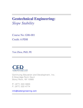
128R.S. SHARP AND D.J.N. LIMEBEERFigure 3. The tyre loading showing a radial deformation of the structure and a mutualdependency of vertical load and sideforce. View from rear.first order lag equations to relate tyre sideforce and aligning torque to sideslip andcamber angles; see Section 3.2.The tyre loading is illustrated in Figure 3 in which it can be seen that the verticalload on the tyre will influence the tyre sideforce via the tyre force model. Thesideforce will in turn affect the vertical load through the equilibrium requirementsof the massless outer ring. Due to the lagging of the tyre lateral forces describedabove and further in Section 3.2, the apparent circular dependency is avoided in themodel. The side forces for the current instant in time follow from the past historyof
Motorcycle model in its nominal state with the key points labelled. generated, select the type of numerical integrator to be installed in the code and to control the symbolic manipulations in various other ways. When the analyst does not exercise choice overtly in these matters, AutoSim uses default settings from a configuration file that the analyst is free to access. 3. Modelling the Motor

![Motorcycle Mechanic [MM] - CTEVT](/img/5/motorcycle-20-20mechanic-2010.jpg)