Transcription
Bridge OfficeMail Stop 6103485 Hadley Avenue NorthOakdale, MN 55128-3307Phone No: 651/366-4500Fax No: 651/366-4497October 30, 2018DISTRIBUTION: MnDOT Bridge Office Web SiteTRANSMITTAL NOTICE (2018-02)MANUALSUBJECTLRFD Bridge Design ManualISSUED BYBridge OfficeDEVELOPED BYBridge OfficeTitle PageTable of ContentsSection 2 General Design and Location FeaturesThe MnDOT Bridge Office LRFD Bridge Design Manual is available for download in Adobe PDF (PortableDocument Format) at http://www.dot.state.mn.us/bridge/. This Web site should be checked regularly forupdates.INSTRUCTIONS:(for two-sided printing)1. Remove from the manual: Title Page Table of Contents pages i through iv Entire Section 22.Print and insert in the manual: Title Page Table of Contents pages i through iv Section 2Note: Because of the numerous changes spread throughout the section, Section 2 is beingrepublished in its entirety. Changes from the previous version are denoted by a single verticalrevision bar located in the right margin. The “OCTOBER 2018” update includes the followingrevisions: Article 2.1.1 - General Criteria was revised for consistency with performance basedpractical design (PBPD) guidance. Article 2.1.2 - Bridge Width Criteria was updated for consistency with PBPDguidance. Article 2.1.2 –Cross Slopes on Bridges was revised to match current practice.
5-392MANUALMINNESOTA DEPARTMENT OF TRANSPORTATIONBridge OfficeLRFD BridgeDesign Manual
MnDOT BRIDGE OFFICELRFD Bridge Design ManualMinnesota Department of Transportation3485 Hadley Avenue North Mail Stop 610Oakdale, MN 55128-3307Phone: 651/366-4500 Fax: 651/366-4497JULY 2003 OCTOBER 2003 JANUARY 2004 APRIL 2004 OCTOBER 2004 DECEMBER 2004FEBRUARY 2005 MARCH 2005 NOVEMBER 2005 MARCH 2006 APRIL 2006 MAY 2006AUGUST 2006 OCTOBER 2006 FEBRUARY 2007 JUNE 2007 JULY 2007 OCTOBER 2007APRIL 2008 MAY 2008 JUNE 2008 AUGUST 2008 SEPTEMBER 2008 OCTOBER 2008APRIL 2009 MAY 2009 OCTOBER 2009 MARCH 2010 JUNE 2010 DECEMBER 2010 JUNE 2011SEPTEMBER 2011 OCTOBER 2011 DECEMBER 2011 APRIL 2012 NOVEMBER 2012 APRIL 2013SEPTEMBER 2013 FEBRUARY 2014 JULY 2014 AUGUST 2014 DECEMBER 2014 MAY 2015JUNE 2015 AUGUST 2015 MAY 2016 JULY 2016 AUGUST 2016 DECEMBER 2016 MARCH 2017OCTOBER 2017 NOVEMBER 2017 DECEMBER 2017 SEPTEMBER 2018 OCTOBER 2018
OCTOBER 2018LRFD BRIDGE DESIGNiTABLE OF CONTENTS1.INTRODUCTION . 1-11.11.21.32.Overview Of Manual 5-392 . 1-11.1.1Material Contained in Manual 5-392 . 1-11.1.2Updates to Manual 5-392 . 1-21.1.3Format of Manual References . 1-2General Bridge Information . 1-21.2.1Bridge Office . 1-31.2.2Highway Systems. 1-91.2.3Bridge Numbers . 1-91.2.4Limit States to Consider in Design . 1-12Procedures . 1-121.3.1Checking of Mn/DOT Prepared Bridge Plans . 1-121.3.2Checking of Consultant Prepared Bridge Plans . 1-131.3.3Peer Review for Major or Specialty Bridges . 1-171.3.4Schedule for Processing Construction Lettings . 1-201.3.5Bridge Project Tracking System . 1-221.3.6Approval Process for Standards . 1-26GENERAL DESIGN AND LOCATION FEATURES . 2-12.1Geometrics . 2-12.1.1Bridge Geometrics. 2-12.1.2Bridge Deck Requirements . 2-22.1.3Bridge Undercrossing Geometrics . 2-92.1.4Bridge Barriers and Railings . 2-162.2Bridge Aesthetics . 2-162.3Preliminary Bridge Plans . 2-172.3.1General . 2-172.3.2Bridge Type Selection . 2-24
OCTOBER 20182.4LRFD BRIDGE DESIGNiiFinal Bridge Plans and Special Provisions . 2-302.4.1Final Design Instructions . 2-322.4.1.1Superstructure . 2-322.4.1.1.1Framing Plan . 2-332.4.1.1.2Bridge Decks and Slabs . 2-332.4.1.1.3Diaphragms and Cross Frames . 2-352.4.1.2Pedestrian Bridges . 2-362.4.1.3Temporary Bridges and Widening. 2-382.4.1.4Bridge Approaches . 2-382.4.1.5Survey . 2-392.4.1.6Utilities . 2-392.4.1.6.1Suspended Utilities & Utilities Embedded in Bridges. 2-392.4.1.6.2Buried Utilities . 2-402.4.1.7Precedence of Construction Documents. 2-472.4.1.8Design Calculation Requirements . 2-472.4.2Final Plans . 2-472.4.2.1Drafting Standards . 2-482.4.2.2Drafting Guidelines . 2-492.4.2.3General Plan and Elevation . 2-512.4.2.4Bridge Layout and Staking Plan . 2-562.4.2.5Standard Abbreviations . 2-592.4.2.6Inclusion of Standard Bridge Details andBridge Standard Plans in Plan Sets. 2-592.4.2.7Standard Plan Notes . 2-602.4.2.8Quantity Notes and Pay Items . 2-612.4.32.5Revised Sheets . 2-63Reconstruction Guidelines and Details . 2-652.5.1Superstructure . 2-652.5.1.1Barriers . 2-652.5.1.2Wearing Course . 2-652.5.1.3Expansion/Fixed Joints . 2-652.5.2Substructure . 2-762.5.2.1Abutments. 2-76
OCTOBER 2018LRFD BRIDGE DESIGN2.5.2.22.6iiiPiers . 2-80Construction Requirements. 2-80APPENDIX 2-A: BRIDGE TYPE NUMBERS . 2-81APPENDIX 2-B: STANDARD ABBREVIATIONS . 2-82APPENDIX 2-C: STANDARD PLAN NOTES . 2-85APPENDIX 2-D: STANDARD SUMMARY OF QUANTITIES NOTES . 2-107APPENDIX 2-E: CONVERSION FROM INCHES TO DECIMALS OF A FOOT . 2-1093.LOAD AND LOAD FACTORS . 3-13.1Load Factors and Combinations . 3-13.2Load Modifiers . 3-43.3Permanent Loads (Dead and Earth) . 3-43.4Live Loads . 3-53.4.1HL-93 Live Load, LL . 3-53.4.2Multiple Presence Factor, MPF . 3-63.4.3Dynamic Load Allowance, IM . 3-63.4.4Pedestrian Live Load, PL . 3-63.4.5Braking Force, BR . 3-63.4.6Centrifugal Force, CE . 3-73.4.7Live Load Application to Buried Structures . 3-73.4.8Live Load Surcharge, LS. 3-73.5Water Loads, WA . 3-73.6Wind Loads . 3-83.6.1Wind Load on Structure, WS . 3-83.6.2Wind on Live Load, WL. 3-93.7Earthquake Effects, EQ . 3-93.8Ice Load, IC . 3-93.9Earth Pressure, EV, EH, or ES . 3-93.10Temperature, Shrinkage, Creep, Settlement, TU, SH, CR, SE . 3-103.10.1Temperature Effects . 3-103.10.2Shrinkage Effects . 3-133.11Pile Downdrag, DD . 3-133.12Friction Forces, FR . 3-13
OCTOBER 2018Sliding Bearings . 3-133.12.2Soil/Backwall Interface and Soil/Footing Interface . 3-13Extreme Event . 3-143.13.1Vehicle Collision, CT . 3-143.13.2Vessel Collision, CV . 3-143.14Uplift . 3-143.15Construction Loads . 3-153.16Deflections . 3-15STRUCTURAL ANALYSIS AND EVALUATION . 4-14.1Design QC/QA Process . 4-14.2Load Distribution . 4-44.2.1Dead Load Distribution . 4-44.2.2Live Load Distribution . 4-54.2.2.1Steel and Prestressed Concrete Beams . 4-54.2.2.2Slab Spans and Timber Decks . 4-64.2.35.iv3.12.13.134.LRFD BRIDGE DESIGNSidewalk Pedestrian Live Load . 4-64.3Load Rating. 4-64.4Substructure Fixity . 4-74.5Structural Models . 4-74.6Design Methodology & Governing Specifications . 4-84.6.1Pedestrian Bridges . 4-84.6.2Rehabilitation Projects . 4-84.6.3Railroad Bridges and Bridges or Structures near Railroads . 4-11CONCRETE STRUCTURES . 5-1
OCTOBER 20182. GENERALDESIGN ANDLOCATIONFEATURESLRFD BRIDGE DESIGN2-1The design of a bridge typically takes place in two major phases of work:preliminary design and final design. During preliminary design, thestructure type, the foundation type, the aesthetics, and the primarygeometry for the bridge are determined. During final design, specificdetails for all of the elements of the bridge are developed and presentedin the plan set. These details include material descriptions, quantities, andgeometric information. Final plan sets are typically assembled in an orderthat roughly follows the order of construction, from the ground up.This section of the manual contains a large amount of information usefulfor the preparation and assembly of plans for a project. To facilitate theproduction of plans and standardize the content of bridge plan sets, theBridge Office has developed special provisions, standard bridge details,standard plans, standard plan notes, and standard pay items.Guidance for the design of specific structural elements (e.g. beams,abutments, piers, etc.) is provided elsewhere in the manual.2.1 GeometricsDefinitionsFor discussion of bridge geometrics in this section, roadways are classifiedas Mainline Highways, Ramps, Local Roads, and Local Streets. Each ofthese four groups is further classified under either Urban or Rural Design.The following definitions apply: Mainline Highways – Roadways that carry through traffic lanes forfreeways, expressways, and primary and secondary highways. Local Roads – Rural roads off the state trunk highway system. Local Streets – Urban roads off the state trunk highway system. Ramps – Segments of roadway connecting two or more legs at aninterchange. Urban Design – Roadways with curbs on the right and/or left sides. Rural Design – Roadways without curbs. Median Width – The distance between the inside edges of opposingthrough traffic lanes. Auxiliary Lane – A lane adjoining a through traffic lane for a purposesupplementary to through traffic movement such as truck climbing,weaving, speed change or turning.2.1.1 BridgeGeometricsGeneral CriteriaThe width of the bridge deck and the typical section at the bridgeundercrossing are determined by the classification and geometrics of theapproaching roadway, together with appropriate design considerations for
OCTOBER 2018LRFD BRIDGE DESIGN2-2shoulder needs. The geometrics of the approaching roadway are to becarried over and under the bridge to the maximum extent practicable.Bridge width requirements are a function of the lane and shoulder widthsof the approaching roadway, together with assessment of pedestrian andbicycle needs, multimodal requirements, user safety requirements,drainage requirements, staging, and other project specific considerationssuch as snow storage and emergency vehicle access. The determinationof the appropriate width for each project requires study of specific projectneeds. Detailed decision documentation is required by the RoadwayDesigner during the preliminary design phase, and must be coordinatedwith the Preliminary Bridge Plans Engineer. Bridge shoulder and lanewidths should be included with project design element documentation inthe District project design memo, including informal design exceptions asnecessary.The discussion of geometric details included in this section describes bridgedeck geometrics separately from bridge undercrossing geometrics.Application of StandardsUnless stated otherwise, the geometrics discussed in the following articlesapply specifically to new work. However, use of these geometrics is alsohighly desirable when upgrading or widening existing facilities and shouldbe incorporated in those situations also. For bridge repair projects, seethe Bridge Preservation and Improvement Guidelines, found on the MnDOTBridge Office web site, for more information. Bridge deck geometrics onthe local road system must comply with State Aid for Local TransportationOperations Rules, Chapter 8820.ResponsibilityThe Preliminary Bridge Plans Engineer will be responsible for assuring thatthe geometric standards in this section are followed. Where a deviationfrom the standard is necessary, a written description of the deviation shallbe prepared by the Preliminary Bridge Plans Engineer and submitted to theState Bridge Engineer for approval prior to submitting the PreliminaryBridge Plan for signature.2.1.2 Bridge DeckRequirementsBridge Width CriteriaRoadway cross sections that approach bridges will normally provide a clearzone recovery area beside the travel lane for the benefit of out-of- controlvehicles. It is not economical or practical to carry these full clear zonewidths across bridges. Since the railing is most often located within the
OCTOBER 2018LRFD BRIDGE DESIGN2-3clear zone, it is considered a hazard and guardrail protection is requiredin the approach area.Roadway shoulder and bridge shoulder width standards have been revisedto allow project designers more flexibility, providing them greater latitudeto address specific project requirements. For the majority of bridges, thebridge width will match the approach roadway width. For longer and/ormore complex bridges, a risk assessment of non-standard width optionswill be performed to determine the appropriate bridge width. Refer to thedocument Performance-Based Practical Design Process and DesignGuidance, found as an attachment to Technical Memorandum No. 18-09TS-07. Go to: mlDetailed design decision documentation should include a checklist leadingto the selected bridge width for the project and must include considerationof the following functions of the shoulder: Recovery area to regain control of a vehicle. Emergency parking area for stalled vehicles and escape route forstranded motorists. Passageway for bicycles and pedestrians. Passageway for emergency vehicles. Parking area for bridge maintenance and inspection vehicles(working area for under-bridge inspection vehicle and lane closurerequirements). Temporary traffic lane during deck repairs or overlayconstruction. Area for deck drainage and snow storage. Accommodation for passing of wide oversize loads, especiallyfarm machinery. Escape area to avoid a head-on collision with an oncomingpassing vehicle on a two-lane highway. Designated bus shoulder lane. Staging needs during construction.For local roads and streets, bridge widths are given in the State AidManual, Section 5-892.210 and the State Aid Operations Rules, Chapter8820.Cross Slopes on Bridges1) Use a cross slope on the bridge traffic lanes that is the same as theapproaching roadway lanes, normally 0.02 ft/ft. The shoulder on abridge may continue at the adjacent lane cross slope or, if betterdrainage is desired, may be 0.005 ft/ft greater than the adjacent lane.If a shoulder functions as a pedestrian access route, cross slopes must
OCTOBER 2018LRFD BRIDGE DESIGN2-4not exceed 0.02 ft/ft to be ADA-compliant. When the bridge deck issuperelevated, provide the same slopes for the shoulders as theadjacent bridge traffic lanes. The 0.005 ft/ft maximum cross slopechange between adjacent lanes and shoulders is determined forconstructability by limiting the need for atypical detailing such asspecial bar bends in the deck. Also note that the greater the change incross slope, the more difficult it is to remove snow to bare pavement.Changes in cross slope between adjacent lanes and shoulders that aregreater than 0.005 ft/ft will be considered where steeper slopes willreduce the number of deck drains on the bridge, but must be approvedby the Preliminary Bridge Plans Engineer. Note that the effects of achanging cross slope are magnified on curved alignments and requireadditional consideration and adjustment of stools, seat elevations, andresulting encroachment on vertical clearances.Keep superelevation transitions off bridges. In instances where theyare unavoidable, it is preferable for ease of deck placement to maintaina straight line across the deck at all locations, because it allows astraight screed between paving rails placed at both sides of the deck.Locate begin and end points of transition breaks at piers.2) Provide ramp cross slopes that are uniform between the bridge curbs.Bridge MedianOn divided highways with a separate bridge for each roadway, the openingsbetween bridges must be a minimum of 8'-0" wide if access for bridgeinspection vehicles is required.Use longitudinal joints along the median of bridges only on bridgeroadways wider than about 100 feet or for other special cases. Byeliminating this joint on bridges with medians, simpler detailing andsimpler construction can be used.Shared-Use Paths and Pedestrian Walkways (Sidewalks) onBridgesShared-use paths are provided on bridges where both pedestrian andbicycle traffic is expected. Bridge walkways are provided where onlypedestrian traffic is expected.The width of bridge shared-use paths and walkways are highly dependenton their context (i.e., factors such as land use, user type, expected volume,state and local non-motorized plans, network connections, trip attractions,overlooks, future growth, and bridge length).
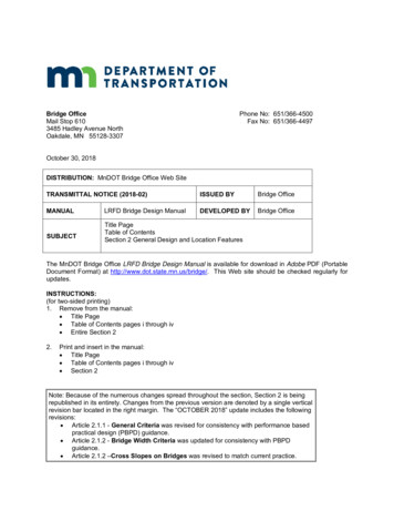
OCTOBER 2018LRFD BRIDGE DESIGN2-5When including pedestrian and/or bicycle traffic on a bridge, note thatsafety, accommodation, and cost must be balanced for all users throughoutthe roadway cross section. This includes balancing the widths of lanes,shoulders, shared-use paths, and walkways, particularly in constrainedcross-sections.The AASHTO Guide for the Development of Bicycle Facilities (GDBF)recommends a minimum two-way shared-use path paved width of 10 feet.The Proposed Guidelines for Pedestrian Facilities in the Public Right of Way(PROWAG) requires a continuous minimum clear public access route (PAR)width of 4 feet and a minimum clear PAR width of 5 feet at intervals of 200feet to allow for passing.On bridges, MnDOT also includes a buffer width added on each side of theshared-use path/walkway in order to protect users from vertical barriersand edge of walkway drop-offs.Use the following guidance for determination of bridge shared-usepath/walkway widths. For local bridges, also refer to State Aid OperationRules, Chapter 8820.1) New vehicular bridgesBest practice is to provide continuity by matching the measured widthof the approach shared-use path/walkway, and adding a 1 foot bufferwidth on each side. See Figure 2.1.2.1. For approach shared-usepaths/walkways that are located immediately behind a curb, theapproach width is measured to the back side of the curb. Integral brushcurbs (maximum of 2 inches wide x 6 inches high) may be included inthe clear width dimension where the total width is greater than 10 feet.For approach shared-use paths not meeting the AASHTO GDBFrecommended minimum width of 10 feet, consult state or local plansand/or the appropriate trail authority to identify the future intent andfeasibility of providing a greater approach path width. Consult withfunctional group experts as necessary.Total bridge shared-use path/walkway widths greater than bestpractice or greater than 12 feet require consultation with the state orlocal authority and/or the appropriate trail authority to identify the needfor additional width. The District and/or local authority must documentthe need for and feasibility of providing this width (plan, cross section,letter, user volume, etc.). Total widths beyond 12 feet requireconcurrence from functional group experts and discussion to determinewhether municipal cost participation is necessary.
OCTOBER 2018LRFD BRIDGE DESIGN2-6The minimum total bridge shared-use path width for new vehicularbridges is 10 feet, which is based on an 8 foot approach shared-usepath (two times the 4 foot PAR width) plus a 1 foot buffer width oneach side. Consideration may be given to a minimum total bridgeshared-use path width less than 10 feet when the approach shared-usepath width is less than 8 feet and/or there is concurrence fromfunctional group experts.For new vehicular bridges that accommodate pedestrian traffic only,the minimum total bridge walkway width is 7 feet, which is based onthe 5 foot PAR width for passing plus a buffer width of 1 foot on eachside.The total bridge shared-use path/walkway width is defined as theminimum clear width measured from the path/walkway side of thecurb/barrier/parapet/railing to the path/walkway side of the oppositecurb/barrier/parapet/railing.For situations where there is nobarrier/parapet on the traffic side of the shared-use path/walkway(raised sidewalk), the measurement is to the top outside edge of theshared-use path/walkway. There, the location of the top outside edgeof the shared-use path/walkway is defined as 1 inch from the gutterline (based on 6 inch curb height x 0.125 slope 0.75 inches, roundedup to 1 inch). Integral brush curbs (maximum of 2 inches wide x 6inches high) may be included in the clear width dimension where thetotal shared-use path/walkway width exceeds 10 feet. See Figure2.1.2.1.2) New pedestrian bridgesFor new pedestrian bridges that carry both pedestrians and bicycletraffic, follow the guidance given in 1) above.For new pedestrian bridges carrying pedestrians only (note that this isa rare occurrence), the minimum total bridge walkway width is 8 feetper the requirements of AASHTO’s A Policy on Geometric Design ofHighways and Streets.3) Bridge repair projectsWhere possible, follow the guidance given in 1) above for bridge repairprojects.On bridge repair projects with constrained cross-sections, the minimumtotal bridge shared-use path width is 8 feet.
OCTOBER 2018LRFD BRIDGE DESIGN2-7On bridge repair projects with constrained cross-sections thataccommodate pedestrian traffic only, the minimum total bridgewalkway width is 5 feet. Consideration may be given to a minimumtotal width of no less than 4 feet where constrained bridge crosssections are less than 200 feet long and there is concurrence fromfunctional group experts. See Figure 2.1.2.1.When the design speed on the bridge is 50 mph or greater, a concretebarrier that meets TL-4 is required between the roadway and the shareduse path/walkway. In addition, a pedestrian or bikeway railing is requiredon the outside of the shared-use path/walkway. For design speeds of 40mph or less, separation with a concrete barrier is not required. For a designspeed of 45 mph, consider the context when determining whetherseparation is needed: Built up urban areas versus open suburban/rural areas. Proximity of approach shared-use path/walkway to roadway andwhether there is adequate cross-section width to provide andterminate approach guardrail. Proximity of intersections to the bridge and whether intersectionsight distance will be affected by inclusion of barrier and guardrail. Volume of pedestrian/bicycle usage on the bridge. Actual operating speed compared to the design speed. Horizontal alignment and location of the shared-usepath/walkway.The curb height for shared-use paths/walkways adjacent to the roadway is6".When a barrier is provided between the traffic lanes and the shared-usepath/walkway, use the bridge slab for the shared-use path/walkway (i.e.,do not provide a raised shared-use path/walkway). Advise the road plansdesigner to provide for any necessary shared-use path/walkway rampingoff the bridge.The minimum cross slope for shared-use paths/walkways is 0.01 ft./ft.
OCTOBER 2018LRFD BRIDGE DESIGNFigure 2.1.2.12-8
OCTOBER 2018LRFD BRIDGE DESIGN2-9Protective Barriers at Bridge ApproachesThe ends of bridge barriers must be protected from being impacted (excepton low speed roads such as city streets). For design speeds over 40 mph,a crash tested guardrail transition is required.Refer to State Aid Operationrequirements on local bridges.2.1.3 BridgeUndercrossingGeometricsRules, Chapter8820forguardrailGeneral Criteria for Lateral ClearanceBridge undercrossing geometrics must rationalize safety requirements withcosts and physical controls such as span length and permissible depth ofstructure. The following guidelines apply in establishing these geometrics:1) SafetyPiers, abutments, side slopes and back slopes steeper than 1:3, andguardrails can all be hazards to an out of control vehicle. It is desirableat all bridge undercrossings to provide a clear zone recovery areabeside the roadway that is free from these hazards. This clear zone isgiven in the Road Design Manual, Section 4-6.04 and is a function ofthe roadway curvature, design speed, ADT, and ground slope. For thearea under bridges a practical maximum clear zone of 30 feet may beused as permitted in the 2011 AASHTO Roadside Design Guide, Table3.1 based on consistent use and satisfactory performance. Eliminateside piers from the roadside area wherever possible. The “desirable”bridge undercrossing will satisfy the above safety criteria.For locations where it is totally impractical to provide a full clear zonerecovery area at an undercrossing (as at some railroad underpassesand in certain urban
OCTOBER 2018 LRFD BRIDGE DESIGN 2-2 2.1.2 Bridge Deck Requirements shoulder needs. The geometrics of the approaching roadway are to be carried over and under the bridge to the maximum extent practicable. Bridge width requirements are a function of the lane and shoulder widths of the approaching roadway, together with assessment of pedestrian and