Transcription
ENGINEERS NOTEBOOKCOLUMNNathan Ho ASHRAE www.ashrae.org. Used with permission from ASHRAE Journal. This article may not be copied nor distributed in either paper or digital form without ASHRAE’spermission. For more information about ASHRAE, visit www.ashrae.org.Performance-BasedApproach to LaboratoryExhaust SystemsBY NATHAN HO, P.E., MEMBER ASHRAELaboratory facilities serve as a critical nexus for innovation and discovery, but theyoften come with the potential for high operational cost (HVAC energy consumption)and high risk (air quality performance). A prescriptive approach to designing laboratory exhaust stacks has been common. It will likely have a place in the future based onthe need for broadly applicable minimum design criteria that can be enforced consistently through code adoption and inspectors. However, achieving superior energyperformance and acceptable air quality requires a performance-based approach tolaboratory exhaust stack design.Examples of Prescriptive Design CriteriaA performance approach begins with an understandingof the origins and limitations of prescriptive design criteria. Local code and recognized industry standards oftenserve as the basis of prescriptive criteria a designer woulduse to design a laboratory exhaust stack. Let us examine the California Mechanical Code, California EnergyCode and the American National Standards Institute/American Industrial Hygiene Association Standard forLaboratory Ventilation (ANSI/AIHA Z9.5) as examples.2019 California Energy Code22019 California Mechanical Code1“502.2.2 Product Conveying Ducts. Ducts conveyingexplosive or flammable vapors, fumes or dusts shallterminate not less than 30 ft (9 m) from a property line,10 ft (3 m) from openings into the building, 6 ft (2 m)60ASHRAE JOURNALashrae.orgfrom exterior walls or roofs, 30 ft (9 m) from combustible walls or openings into the building that are in thedirection of the exhaust discharge and 10 ft (3 m) aboveadjoining grade. (Emphasis is the author’s.)Other product-conveying outlets shall terminate notless than 10 ft (3 m) from a property line, 3 ft (914 mm)from exterior walls or roofs, 10 ft (3 m) from openingsinto the building and 10 ft (3 m) above adjoining grade.”(Emphasis is the author’s.)SEPTEM BER 2020“140.9 (c) Prescriptive Requirements for CoveredProcesses, Prescriptive Requirements for Laboratoryand Factory Exhaust Systems.Nathan Ho, P.E., is an associate principal and engineering group leader with P2S Inc., in Irvine,Calif. He is the chair of ASHRAE SPC 110.
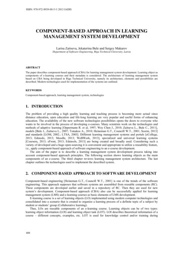
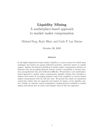
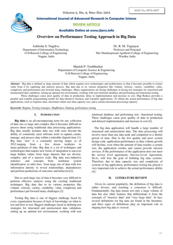
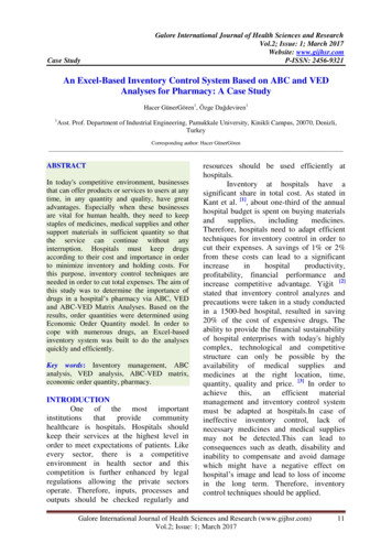
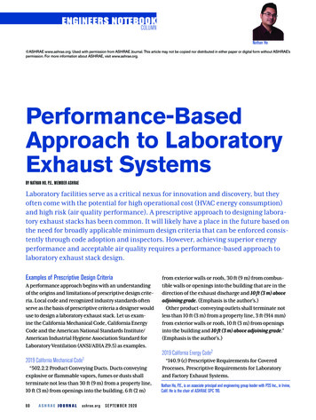
COLUMN ENGINEER’S NOTEBOOKFIGURE 1 Results vs. effort qualitative comparison of analysis methods.AccurateWind Tunnel ValidationResults3. Fan System Power Consumption. All newly installedfan exhaust systems serving a laboratory or factorygreater than 10,000 cfm (4719 L/s) shall meet subsectionA and either B, C or D:A. System shall meet all discharge requirements in ANSIZ9.5-2012.” (Emphasis is the author’s.)ANSI/AIHA Z9.5-2012, Laboratory Ventilation3“5.4.6 Exhaust Stack Discharge. In any event the discharge shall be a minimum of 10 ft (3 m) above adjacentroof lines and air intakes and in a vertical up direction.Exhaust stack discharge velocity shall be at least3,000 ft per minute (fpm) (15.2 m/s) [emphasis is theauthor’s] unless it can be demonstrated that a specificdesign meets the dilution criteria necessary to reducethe concentration of hazardous materials in the exhaustto safe levels at all potential receptors.The air intake or exhaust grilles shall not be locatedwithin the architectural screen or mask unless it is demonstrated to be acceptable.”A relationship exists between codes and standards.Often, codes are mostly sections of existing industrystandards with modifications made by the authorityhaving jurisdiction. Therefore, to identify the designparameters to address with a performance approach tolaboratory exhaust stack design, it is necessary to understand the context and limitations of the referenced standard. It is also essential to keep in mind that the prescriptive criteria for stack height and exit velocity havesubstantial disclaimers, such as the one in Appendix 3 ofANSI/AIHA Z9.5-2012.ANSI/AIHA Z9.5-2012 Appendix 3, Selecting Laboratory Stack Designs3“The 10 ft (3.05 m) minimum stack height called for inthe body of this standard is primarily intended to protect maintenance workers from direct contaminationfrom the top of the stack. However, the minimum heightof 10 ft (3.05 m) is not enough by itself to guarantee thatharmful contaminants would not be re-ingested. (Emphasisis the author’s.)Similarly, a minimum 3,000 fpm (15.3 m/s) exit velocity is specified in the body of this standard, but this exitvelocity does not guarantee that re-ingestion will not occur.”(Emphasis is the author’s.)It has been the author’s experience that stack height,exhaust plume exit momentum and physical locationwith respect to building massing, site topography andComputationalFluid Dynamics2019 ASHRAEHandbook—HVACApplicationsCalculation MethodConservativeEffort and Resources Requiredareas sensitive to air quality, such as outdoor air intakes,operable windows and populated areas, are critical variables that must be evaluated holistically to achieve optimum design outcomes.Many laboratory projects are developed as renovations; as such, the site topography and areas sensitive toair quality are typically fixed variables, and the optionsof locations to install the laboratory exhaust systems areoften limited. Therefore, stack height and exit momentum are usually the remaining variables a design teamcan explore and evaluate. This column presents a basicframework for a design process and a case study highlighting the results of this process when applied to alaboratory renovation project.Figure 1 presents three conventional methods to evaluate laboratory exhaust plume dispersion performanceand qualitatively ranks what a designer can anticipateconcerning the accuracy vs. effort trade-off betweeneach method. The designer should exercise extremecaution when using computational fluid dynamics(CFD) to model exhaust plumes for laboratory pollutantsources, as CFD models can both over- and underpredictconcentration levels by orders of magnitude, leading topotentially unsafe designs.4 The author agrees with the2019 ASHRAE Handbook—HVAC Applications, Chapter 46recommendation to use a wind-tunnel analysis to validate the results from a CFD analysis.Figure 2 describes a process this author has used tocollaborate with design team stakeholders to achieveoptimum laboratory exhaust system design based onthe project priorities and values. Step 5 is optional,but recommended by the author to achieve optimumdesign results; wind tunnel validation can yield substantially more accurate performance results with higherconfidence than computational modeling or manualSEPTEM BER 2020ashrae.orgASHRAE JOURNAL61
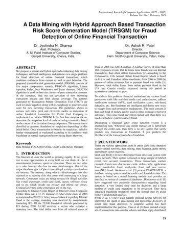
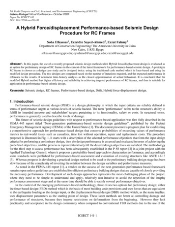
COLUMN ENGINEER’S NOTEBOOKcalculation results. The following case study is an example of how all five steps of the collaborative design process were used on a project.FIGURE 2 Collaborative design input cycle to optimize design of lab exhaust system.Case Study—Institutional Research Laboratory in SouthernCalifornia: Prescriptive vs. Performance DesignA research-focused higher education institution setCollaborative EffortOwner, Mechanical Engineer,out to renovate a historic building to provide a modernWind Consultant, Architect,laboratory facility for a newly recruited principal invesStructural Engineer etc.tigator and her team. Given the potential for growthof the research, the laboratory program required ahighly flexible HVAC system that could provide stable,responsive and reliable operation on day one, while alsobeing capable of supporting rapid growth. This institution decided to use a design-build delivery to mitigate1 Identify primary design variables and objectives.potential construction budget and schedule risks and2 Collaborate with owner and design team to determine project priorities to optimizebalance between variables. Develop early design concept based on this input.provided the criteria as part of the bridging documents Perform preliminary analysis of design concept performance based on the3(Table 1).2019 ASHRAE Handbook—HVAC Applications, Chapter 46 Calculation Method orThe university requested a wind study to inform theComputational Analysis. If preliminary results are not compatible with projectrequirements, return to Step 2 and iterate as necessary.design of the HVAC system and provide the university Produce detailed design layout and evaluate constructibility.4with metrics on air quality to mitigate the risk of odor5 Confirm feasibility of design concept and execute wind tunnel validation of performance.or air quality concerns. The wisdom of this decisionUse results to finalize hardware and controls design. Iterate process as necessary toachieve optimum project solution.became immediately apparent upon inspection of theproject site shown in Figure 3.A typical first cost vs. energy effiTABLE 1 Project background information and owner design criteria.ciency discussion took place withinPROJECT BACKGROUND INFORMATIONUNIVERSITY DESIGN CRITERIAthe design-build team. Our team1954 five-story building with three stories above grade.Centralized laboratory exhaust system.agreed to compare a code-drivenContinuously renovated to suit changing research needs.N 1 fan redundancy, minimum three fans total.prescriptive lab exhaust design toa performance laboratory exhaustOrganic addition of fume hoods over time.Motorized isolation dampers and backdraft dampers.design (Table 2). The code-drivenPerform study of wind and air quality conditions toNew lab renovation requires additional lab exhaust informdesign of laboratory exhaust stacks and rooftopprescriptive lab exhaust design usesinfrastructure and new rooftop air-handling unit.air-handling unit outdoor air intake.bypass air to enable variable airvolume (VAV) laboratory ventilationFIGURE 3 Rooftop topography and existing conditions.controls within the building whilemaintaining a constant volumedischarge.The performance laboratoryexhaust design is capable of elimiProposed New Lab Exhaust Existing Lab Exhaust FansOn Adjacent RoofAnd AHU Areanating bypass air and achieving VAVdischarge to minimize exhaust fanExisting Lab Exhaustenergy consumption along withFans on Same Roofreduced sound power, operationalExisting Lab Exhaust Fanscomplexity and wear on fan bearOn Adjacent Roofings. See Figures 4 and 5 for screenshots of our model for the prescriptive exhaust system design option62ASHRAE JOURNALashrae.orgSEPTEM BER 2020
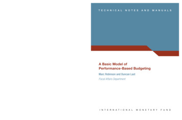
COLUMN ENGINEER’S NOTEBOOKTABLE 2 Exhaust system design features: prescriptive vs. performance.PRESCRIPTIVE EXHAUST SYSTEM FEATURESPERFORMANCE EXHAUST SYSTEM FEATURESSeparate exhaust stacks terminating at10 ft above the finished roof.Clustered exhaust stacks terminating at24 ft above the finished roof.Discharge nozzles to achieve target exitvelocity of 3,000 fpm.No discharge nozzles on stacks topromote fully developed turbulent airflowprofile at exit of stack.aBypass air to maintain constant dischargeair volume at the exit of each stack.No bypass air.“Hidden” outdoor air intake.“Hidden” outdoor air intake.FIGURE 4 Prescriptive exhaust system design concept, viewed from the south.FIGURE 5 Prescriptive exhaust system design concept, viewed from the north.aMany numerical distribution models use the Briggs plume rise formulas that were based on fully developedturbulent flow profiles at the stack exit.5 It has been speculated that using a nozzle on the discharge of thestack could compromise the stack’s ability to achieve fully developed turbulent flow profiles at their point ofdischarge.and Figures 6 and 7 for the performance exhaust systemdesign option.Visual inspection of the existing rooftop conditionssuggested that existing-to-remain nearby laboratoryexhaust fans may render the rooftop air unsuitable asa source of outdoor air for the new air-handling unit.Therefore, our team decided to “hide” the outdoor airintake from the existing rooftop exhaust fans to passively enhance the air quality of the outdoor air broughtin through the air-handling unit. Per the 2019 ASHRAEHandbook—HVAC Applications,4 a conservative dilutionfactor of 2.0 may be anticipated when the air intake is“hidden” from the line of sight of an emissions source.To provide an objective analysis of exhaust stack design,the air-handling unit outdoor air intake was kept identical in both design options evaluated.The prescriptive-based and performance-basedexhaust stack design options were both located as farfrom the roof edge as practical to minimize the effectsof the wake zone formed by wind passing over the edgeof the roof. Exhaust stacks that terminate within the“recirculation region” of a wake zone will tend to requiresubstantially more power for their exhaust plume toescape the roof (Figure 8).Laboratory exhaust plume dispersion performancetends to be strongly influenced by stack height and themomentum of the exhaust stream exiting the stack.Discussions with the facility owner confirmed that amaximum stack height of 24 ft (7 m) above the roof wasaesthetically acceptable. So our team used this heightto minimize the exhaust stream momentum requiredto achieve adequate exhaust contaminant dilution. Ourteam then applied the knowledge gained from ASHRAEresearch project RP-1167, “The Effect of Ganging on64ASHRAE JOURNALashrae.orgSEPTEM BER 2020FIGURE 6 Performance exhaust system design concept, viewed from the south.FIGURE 7 Performance exhaust system design concept, viewed from the north.Pollutant Dispersion from Building Exhaust Stacks,” topassively enhance the exhaust plume momentum byclustering the exhaust stacks. Per ASHRAE RP-1167, terminating stacks within a range of 1.3 diameters of thestack centerline with similar discharge velocities frommultiple active stacks will yield conditions where theplume from each active stack will tend to merge, combining m
ANSI/AIHA Z9.5-2012. ANSI/AIHA Z9.5-2012 Appendix 3, Selecting Laboratory Stack Designs. 3 “The 10 ft (3.05 m) minimum stack height called for in . the body of this standard is primarily intended to pro-tect maintenance workers from direct contamination from the top of the stack. However, the minimum height of . 10 ft (3.05 m) is not enough by itself to guarantee that harmful contaminants .