Transcription
TITLE:Working ProcedureRECOMMENDED:APPROVED:REV. DATE:S. Jones, S. KellyB. Hazlett, P.Eng.2020-01-14NO:DFS0004REV:6ELECTRICAL DISTRIBUTION GIS & CADCONSTRUCTION DRAWING STANDARDFor Hydro Ottawa Use Only 2020DFS0004 R6Page 1 of 28
REVISION SHEETRevisionDescription of ChangeDateInitials0Original Document2002-12-18mm/csm1Revise Document Title2003-04-01pl/csm2Major Revision2011-08-02mm/lv3Revised Legends, Schedule H,Request for Drafting Form andStandard Drawings2012-07-26slj/mm/lv4Corrected grammatical errors,Added definitions, Revised CADDelivery Requirements, Requestfor Drafting Services, Formattingand Schedules, Project Legends,and more examples2015-03-06mt/sw/csm5Revised document to incorporate productchange from Microstation to Autocad. Fontchanged to Arial. Reflecting new proposaldrawing changes, and data table changes.Minor updates as Add section about manhole details to replaceobsolete and not approved DFS0016,Removed Section 7For Hydro Ottawa Use Only 2020DFS0004 R6Page 2 of 28
TABLE OF CONTENTSPAGE1Introduction . 52Reference Documents. 53Scope . 54Definitions. 55Software Applications . 75.1AutoCAD . 75.1.1 AutoCAD Drawing Environment . 75.2Geographic Information System . 76Drawing Composition and Format . 76.1General Format . 76.2Source Landbase . 86.3Key Map . 86.4Legend . 86.5Title Block . 86.5.1 Drawing Title . 86.5.2 Project Numbers . 86.5.3 Drawing Preparation by External Parties . 86.5.4 Revisions. 96.5.5 Sheet Numbering . 96.5.6 General Notes . 96.5.7 Project Notes . 96.5.8 Technical Equipment Sizing. 96.5.9 Related Projects . 96.5.10 Orientation North . 96.5.11 Units of Measurement . 96.5.12 Mapping Coordinate System Standard . 106.5.13 Dimensioning . 106.5.14 Drawing Scale . 106.6Drawing Sheet Size . 106.7Plotting . 106.8Primary Single Line Diagrams . 106.9Manhole Details . 106.10Construction Data Tables . 116.11Proposed Cable Works Tables . 116.12Details . 116.13Profiles and Cross Sections. 116.14Residential Lot Servicing . 127CAD Data Delivery to Hydro Ottawa.127.17.27.3CAD Data Delivery Requirements . 12Delivery Media . 13Graphic Attributes and Symbology . 138Equipment Nomenclature .139Requests for Drafting Services .139.19.29.3Drafting Request Form . 13Construction Data Tables and Proposed Cable Works Tables . 13Project Specific Notes and Details . 13For Hydro Ottawa Use Only 2020DFS0004 R6Page 3 of 28
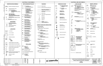
10Drawing Approval.1411As-Built Requirements and Project Closure .14Schedule 1 – Construction Data Table Examples .15Schedule 2 – Proposed Cable Works Table Example .17Schedule 3 – Legend .18Schedule 4 – Primary Single Line Drawing Example.20Schedule 5 – Drafting Request Form .21Schedule 6 – Manhole Detail Example.22Schedule 7 – Project Proposal Drawing Abbreviations.23Schedule 8 – Standard Title Block General Notes .26Schedule 9 - Residential Servicing Guideline .27Schedule 10 - Proposal Drawing Examples .28For Hydro Ottawa Use Only 2020DFS0004 R6Page 4 of 28
1 IntroductionThis standard document was developed to ensure consistency in the preparation of new distributionconstruction proposal drawings. All proposal drawings shall be prepared following the standards outlinedin this document.2 Reference DocumentsHydro Ottawa - DFS0002 “Electrical Distribution As-Built Construction Drawings”Hydro Ottawa - DFS0007 “Control, Revision, Obsolete, and Retention of Engineering technical basedStandards Documents”Hydro Ottawa - DFS0008 “Date and Time General Standard”Hydro Ottawa - DFS0011 “Unit of Standard Measurement – Metric”Hydro Ottawa - DFS0012 “Signing Authority for Technical Based Documents”Hydro Ottawa - DFS0017 “Placing Construction Proposals in GIS”Hydro Ottawa - DFS0019 “Technical Drawing Profiles Requirements”Hydro Ottawa - DNS0002 “CAD Symbology Definition”Hydro Ottawa - DSS0006 “Distribution and SCADA Drawing and Mapping Symbology Standard ”Hydro Ottawa - ESG0001 “Construction Verification Program (CVP)”Hydro Ottawa - ECS0031 “Digital Base Mapping Requirements for Electrical Servicing”Hydro Ottawa - GAP0006 “Paper & Digital Folder Layout”Hydro Ottawa - GCS0012 “Cable Tagging Identification”Hydro Ottawa - GDP0004 “Operating Maps Updates - the Patch Process”Hydro Ottawa - GDG0010 “Project Coach”Hydro Ottawa - NPS0001 “Nomenclature for the Electrical System and Associated Functions”3 ScopeThis standard document sets the minimum requirements for the preparation of proposed commercial,residential, underground, overhead, and fibre routing proposal drawings using Computer-Aided Drafting(CAD) and Geographic Information System (GIS) tools.4 DefinitionsAs-Built Drawings: Any proposal drawing that has been returned from the field with or withoutinstallation design changes following construction shall be processed as a final legal record of theinstallation.GIS/CAD Technician: A Hydro Ottawa staff position whose role is to prepare drawings using GIS and/orCAD.Central Registry: Digital mapping maintained and provided by the City of Ottawa. The maps indicate thelocation of underground utilities contained within the public right-of-way. For the utilities that participate inthe Ottawa Utility Coordinating Committee (UCC).Civil Drawings: Shows proposed geo-referenced Hydro Ottawa supporting structures that are notconnected electrically to the distribution system. Typically these structures include trench lines, ducts,transformer pads, poles, manholes, and service drops. A civil drawing will generally not include a displayof electrical distribution equipment unless deemed necessary for clarity.For Hydro Ottawa Use Only 2020DFS0004 R6Page 5 of 28
Construction Data Table: Used in conjunction with reference note numbers on the plan view; theConstruction Data Table provides detailed information on which standard to use and includes relevantconstruction notes associated with the reference number. See Schedule 1 for examples of data tables.Electrical Drawings: Shows proposed Hydro Ottawa electrical equipment in a semi-geographic state.Includes display of transformers, switches, switchgear and associated hardware, elbows, FCI’s, etc. Ductformations are populated with cable routing tag data, as well as, primary and secondary nomenclature.Formations: A formation is a cross-section of a duct or duct bank placed immediately adjacent to theduct in plain view. The formation graphics will indicate the duct structure layout, type of duct structure,cables/circuits, and duct status (i.e capped or blocked) for each duct.Geo-Referencing: Process of assigning spatial coordinates to data.GIS & Distribution Records: The department that maintains ownership of the old and new equipmentidentification records and systems.Landbase: Refers to the non-electrical map fabric background display in GIS. Landbase includesbuildings, pavement edges, property lines, etc.Operating Maps: Electrical distribution maps created in a non-geographic/schematic format. Thesedrawings are used to indicate the current status of the primary distribution system for Hydro Ottawa’sSystem Office.Project Management: The application of knowledge, skills, tools, and techniques to execute the projectrequirements.Proposal Drawings: Any new electrical and civil drawing that is being prepared in a design state.Records Administrator: A Hydro Ottawa staff position whose role is to provide administrative services,including maintaining existing/old nomenclature systems and issuing new permanent nomenclature.System Office: Hydro Ottawa’s primary operations centre; responsible for controlling the electricaloperation of the distribution system and for issuing controlled temporary nomenclature.System Designer: Hydro Ottawa staff position whose role is to design the proposed civil/electricalinstallation, coordinate all involved parties and manage the project through to completion.For Hydro Ottawa Use Only 2020DFS0004 R6Page 6 of 28
5 Software Applications5.1AutoCADThe standard vector CAD software used at Hydro Ottawa is AutoCAD and will be used to prepare or editthe following: All Landbase files which includes; topographic
connected electrically to the distribution system. Typically these structures include trench lines, ducts, transformer pads, poles, manholes, and service drops. A civil drawing will generally not include a display of electrical distribution equipment unless deemed necessary for clarity.File Size: 1MBPage Count: 28
