Transcription
UCA, INC.ACCESS CONTROL SOLUTIONEternity 4Eternity 5Manual
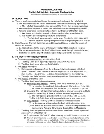
TABLE OF CONTENTSSECTION 1 GENERAL OVERVIEW . 4I.Foreword . 4About This Manual . 4Safety Warnings and Cautions . 4Design Change Disclaimer. 4Reproduction Disclaimer . 4Technical Support . 4II. Important information. 4Manufacture Default Code Setting: . 4LED and Audio Indicator:. 4Important Keys:. 4III. General Lock Spec. 5IV. UCA Eternity IV Datasheet (Heavy Duty keypad Lock). 6Hardware Spec . 6Functions. 6Ordering Information . 6Door Prep . 7Parts List . 7Eternity IV Installation Instruction . 8V. UCA Eternity V Datasheet (Medium Duty keypad Lock). 9Hardware Spec . 9Software Spec . 9Mortise Spec . 9Ordering Information: . 9Eternity-V-Installation . 11Eternity-V-Mortise-Installation . 13SECTION 2 ETERNITY SOFTWARE GUIDE. 161.SOFTWARE SETUP . 16Operating System. 16Installing 1-Wire USB Driver First. 16Installing the iKeypad Software. 16Login . 16Change System Password . 172. ACCESS CONTROL MANAGEMENT I. 17I. Lock Setup . 17New Lock Set Up. 17Edit An Existing Lock. 18II. User Setup. 19Onsite User Setting . 19 Add/Edit user information. 19 Assign Onsite user to lock . 20Copy Lock Setting . 20Remote User Code Setting. 21 Create remote Access Code . 21 Terminate a lost Access Code:. 21 One Time Service code . 223. ACCESS CONTROL MANAGEMENT II . 22III. Time Setting . 22Time Shift Setting . 22Timed Operation Setting. 22Page 2 of 36
Activation / Expiration Date Setting. 23Exception Date Setting. 24IV. Mission Management. 24Set Parameter Key. 24Set Time Key . 25Get Information Key . 25Lockout Key. 26One-Off key/One-Off Code . 26 One-Off Key . 26 One-Off Code. 26V. Audit Trial . 27VI. History . 28Lock Audit History . 28Access Code history. 29Operator Log. 29SECTION 3 NON-SOFTWARE GUIDE . 29I. General Information:. 30II. Manufacture Default Setting: . 30III. Steps to setup a new lock (please follow the order) . 30IV. Types to operate the lock:. 30V. Terms:. 31VI. Functions . 31Weekly Chart . 33 How to program schedule with an “user code”. 334. ENDING TIME . 34SECTION 4 CASE STUDY . 34University Park Business Center, Denton, TX. 34SECTION 5 TROUBLE SHOOTING GUIDE . 35WARRANTY REGISTRATION FORM . 36Page 3 of 36
Section 1 General OverviewI. ForewordAbout This ManualThis manual is designed for users of UCA Eternity 4 and Eternity 5. All installation, setup, operational information,procedures, screen captures, and other relevant materials are contained in this manual.Safety Warnings and CautionsWhen handling a printed circuit board (PCB), guard against possible static discharges by touching a grounded objectBEFORE touching the board. Static shock could cost unexpected damage of the board.Design Change DisclaimerDue to design changes and product improvements, information in this manual is subject to change without notice. UCAassumes no responsibility for any errors that may appear in this manual.Reproduction DisclaimerNeither this manual nor any part of it may be reproduced, photocopied, or electronically transmitted in any way withoutthe written permission of UCA.Technical SupportWhen you experience any difficulty installing or operating the Eternity software, please contact your local distributor orUCA at 1-866-241-9874.II. Important informationManufacture Default Code Setting:1. Default Setting for Login User Name / Password is: dallas / ibutton2. Operator Password: The default operator password is 00000000 (8 digit Zeros)3. System Password: The default System password is 000000 (6 digit Zeros)LED and Audio Indicator:1.2.3.4.5.6.Program Mode: LED indicating GREEN, audio end with two beeps (Successful)Program Mode: LED indicating Red, audio end with one beep (Fail)Key Access Mode: LED indicating GREEN, audio end with two beeps (Valid Access)Key Access Mode: LED indicating Red, audio end with one beep (Fail)Unlock Mode: LED flashing GREEN, lock is in unlock modeLock Mode: LED flashing RED, lock is in lock modeImportant Keys:1. DS1982/DS1990- User Key (Default key-fob color from UCA: red, yellow, black, orange)2. DS1994/DS1904- It contains an on board real time clock to reset the lock internal clock. (Default key-fob color fromUCA: Green)3. DS1977- Program Key. (Default key-fob color from UCA: Purple)4. DS1996- Firmware Upgrade Key (Default key-fob color from UCA: Blue)Page 4 of 36
III. General Lock SpecThis page shows the similar specifications of the Eternity 4 and Eternity 5.Keypad: 12 all weather numeric keypadKeypad Functions: Permanent codes, Temporary codes, one-time service codesPower Supply: 4 standard AA batteries with a weatherized battery pack for all weather conditionsPower Supply Life Expectancy: 10,000 operations, low battery warning when system drops below 4.8 voltsMemory Retention: Flash memory never looses memory even without powerProgramming / Communication Method: iButton key-fob, no annoying wiresFunctions: Time zones for lock function (automatically unlock or lock), fully programmable exception dates (holidays),temporary dates, and time zones for iButton key-fobs.Finishes: Stainless, or Brass.Handles: Reversible LeverAudit Trail: 4000-event audit trail.iButton Users: 500Temporary Codes: No limitPermanent Codes: 300One Time service code: 10Anti-tamper: Red-warming light stays on for 60 seconds after 3 consecutive invalid code entriesKey Bypass: Standard on all unitsDoor Preparation: Standard ANSI A115 Series Prep, optional by adding additional 5/8” through-bolt holes to addstability to the lock and increase security.Strike Plate: ANSI Standard 115.3. Square corner, 1-1/8 x 2-3/4 inch T strike with 1-1/4 lip-to-center dimension.Latch: 2 3/4 inch backset standard (2 3/8 inch backset optional), solid brass with 1/2-inch throw 1-inch diameter bore isrequired.Materials: Zinc AlloyTemperature: 0 F-120 F (-18 C-50 C)Exposure: All weather conditionsAccessibility Standard: Meets ADA standards Americans with disabilities act.Lock Back Time: 1 – 25 seconds (default is 5 seconds)Working Voltage: 4.8-6.4VLow Battery Warning: 4.8V or lowerDoor Thickness: 1 3/8" to 2"Keyway: Schlage C 6Page 5 of 36
IV. UCA Eternity IV Datasheet (Heavy Duty keypad Lock)Hardware SpecPARAMETERLock WeightWorking CurrentIdle CurrentLock Back TimeWorking VoltageLow Battery WarningPower SourceKeypadHandleDoor ThicknessKeywayPacked WeightPacked SizeCTN WeightCTN SizeDETAIL6 Lb 10 mA5 µA5 (1 – 25) Seconds4.8-6.4V4.8V or lower4 AA Alkaline BatteriesWeather Proof KeypadReversible Lever1 3/8" to 2"Schlage C 6FunctionsDESCRIPTIONAudit TrailiButton Key UsersKeycode UsersTimed OperationAuto Lock/Auto UnlockPassage ModeTime Shift UserRemote AccessStorehouse/Classroom ModeOne Time UseiButton UserPermanent Code UserRemote Code UserOne-Touch Lock from InsideDaylight SavingLock Out FunctionUser Key Assignment MethodSoftware PackageSOFTWAREYes (3000 entries)800 (Combine iButton and code)See aboveYes16 time schedules16 time schedules16 time schedulesYesYesYesYesYesYesYesYesYesSoftware Programming KeyYesNON-SOFTWAREN/A300 (Combine iButton and code)See aboveYesFixed time schedule (7 days a week)Single time scheduleSingle time )Ordering E-IV TM Keypad Satin Chrome Lockset SW VersionE-IV TM Keypad Satin Chrome Lockset No SW VersionEternity Schlage C 6-Pin Master Key CylinderDESCRIPTIONDS1977 Programming KeyDS1994 Internal Clock KeyDS1990 iButton User KeyiButton Reader (iButton PC Receptor)USB PC AdapterEternity Lock Management Software ySWCDPack List:1. Front Handle2. Back Handle3. Front Lock4. Back Lock5. Accessory Box Latch Cylinder ScrewsPage 6 of 36
Door PrepParts List12345678iButton ReaderKeypadOutside Lock HousingOutside LeverOverride CylinderOutside GasketLatchInside Gasket9101112131415Inside Mounting PlateBatteries Housing CoverInside Lock HousingInside leverSpindleStrike PlateDust BootPage 7 of 36
Eternity IV Installation InstructionStep 1. Install the latch Insert the latch into 1″ hole on edge of thedoor. Secure the latch in place with two screws.Step 4. Install inside lock housing Plug the power cable into theinside lock housing. Place inside lock housing ontop of the mounting plate, Ensure the square spindle intoinside lever hub. Secure theinside lock housing with twoscrews.Fig. 5Fig. 1Step 5. Install inside lever door handle.Step 2. Install outside lock housing Place the outside gasket (if required) on back of theoutside lock housing prior to the assembly; align thegasket along the edge of the lock housing. Insert the square spindle into the center hub and turnthe spindle until it locks. Ensure that the Dot oncenter hub is point to left.Fig. 6Step 6. Install outside lever door handle Ensure override shaft inside thecylinder housing is in vertical position(use flat screw driver to adjust theposition when needed) Place the outside lockhousing against the door,feed the power plugthrough the 2 1/8 inchdoor hole.Fig. 7 Fig. 3Step 3. Install inside mounting plate Place the inside gasket (if required) on themounting plate, and align the insidegasket with the position hole. Feed the power plug through thesmall hole on the mounting plate. Place the mounting plate against thedoor, and secure the mounting plateattach to outside lock housing withthree screws.Fig. 4 Place the key cylinder into the outsidelever door handle, insert the manualkey to the cylinder and turn clockwise90 degrees.Guide the cylinder into the cylinderhousing and snap the lever doorhandle into the lever catch pinTurn the manual key counterclockwise 90 degree and pull the keyoutStep 7. Install Strike plate Inset the dust boot into thedoorframe. Place the strike plate overthe dust boot. Secure the plate in placewith two screws.Fig. 8Page 8 of 36
V. UCA Eternity V Datasheet (Medium Duty keypad Lock)Hardware SpecPARAMETERWeight (Lock only)Working CurrentIdle CurrentMotor Running TimeWorking VoltageLow Battery WarningPower SourceKeypadHandleDoor ThicknessKeywayDimension (1ps)Dimension (8pcs/box)Package Weight (1)Weight (8pcs/Box)DETAIL4.2 Lbs250 mA15 µA0.4 Second4.2-6.4V4.2V4 AA Alkaline BatteryWeather Proof KeypadNon handed1 3/8" to 2"SC 6 Pin10 x 8 x 4 ½”16 x 10 ½ x 19”5 Lbs40 LbsSoftware SpecDescriptionAudit TrailUsersTimed OperationRemote AccessStorehouse/Classroom ModeOne Time UserSoftware PackageLock from InsideSet Up MethodDaylight SavingLock Out FunctionSoftwareYes. eNo299YesYesYesYesNoNoKeypadYesYesRegular LatchDeadboltMortise Spec3/4" throw heavy duty deadbolt with anti-saw hardened pinsRustproof heavy duty 2 3/8" backset lock caseIndividual spring to prevent lever sag, easily reversibleForged brass lever handles exceed requirements of ADAAuxiliary latch boltHeavy Duty 1/2" latch bolt with anti-friction latch, easily reversibleInterconnected Deadbolt Mortise:While unlocked turn the handle up to enable (lock) the deadbolt, orturn the handle down to disable (unlock) the deadboltInterconnectedDeadbolt MortiseTurn handle up to lockOrdering TIONE5 Software LockE5 Non-Software LockMaster CylinderProgramming ONProgramming KeyClock KeyUser KeySoftware CDPage 9 of 36
Major Lock PartsBack View .17.18.19.20.21.22.Rear HandleRear Lock housing ScrewsRear HousingBattery Plate ScrewBattery PlateRear Rubber GasketDoorLatchLatch ScrewsDust BootStrike PlateFront Lock Fastener PostSquare ShaftFront Rubber GasketFront Lock HousingPosition PinUpper Fastener Post (optional)Attachment Screw (optional)iButton ReaderKeypadOverride Key CylinderFront HandleAccessory Parts ListFront ViewInstallation1.2.3.4.5.6.7.19208.219.Battery Plate Screw (3)Back Cover Screw (2)Screws (4)Square Shaft (1)Position Pin (1)Fastener Extension (2)Upper Fastener ExtensionLatch (1)Strike Plate (1)10.Dust Boot (1)11.Override Key (2)12.SC4 Cylinder (1)13.iButton key (Optional)22Page 10 of 36
Eternity-V-InstallationStep 1Insert the latch into doorhole. Secure the latch withtwo screws.Step 2Insert the square shaft (A) into the center hub (B) (Fig 1). Insert the positionpin into the hole on the center hub to secure the square shaft. Bend the endof position pin around the center hub to secure the pin in place. (Fig 2)EnlargedFig 1Fig 1BFig 2AStep 3Screw in and tighten the two fastener extensions(C) into the front lock fastener posts located onboth side of the center hub. Attach and tightenthe upper fastener extension (D) if needed (Fig3). Note: The upper fastener extension (D) isoptional.Step 4Place the front lock housing onto the door, with therubber gasket (E) between the door and lock housing.Feed the power plug (F) through the hole (Fig 4).ED (optional)CCFFig 4Fig 3Page 11 of 36
Step 5Attach the battery plate onto the door, with therubber gasket between the door and batteryplate. Make sure the power plug go through thehole on the plate. Secure the battery plate tofront lock fastener post with 2 screws. Fastenupper fastener post (Optional) (Fig 5)Step 6Install batteries, and plug in the powercable. Secure the back lock housing ontothe battery plate. Fasten with 2 screws.Press both catch pin in and snap the rearhandle into drive shift (Fig 6)Fig 6Fig 5Step 7Place the override cylinder into front handlehousing, insert override key through the hole intocylinder. Turn the override key 90 clockwise.Press both catch pin in and snap the front handleinto drive shift. Turn override key 90 counterclockwise and pull the key out. (Fig 7)Step 8Put strike box in doorframe, andthen strike plate over it. (Fig 8)Fig 8Fig 7Page 12 of 36
Eternity-V-Mortise-InstallationStep 1Insert the lock case into mortisepocket. Secure the lock case withtwo screws.Step 2Insert the square shaft (A) into the center hub (B). (Fig 1)Insert the position pin into the hole on the center hub tosecure the square shaft. Bend the end of position pinaround the center hub to secure the pin in place. (Fig 2)EnlargedFig 1Fig 1BFig 2AStep 3Screw in and tighten the two fastener extensions (C)into the front lock fastener posts, located on both sideof the center hub. Attach and tighten the upperfastener extension (D) (Fig 3) Note: The upperfastener extension (D) is optional.Step 4Place the front lock housing onto the door, withthe rubber gasket (E) between the door andlock housing. Feed the power plug (F) throughthe hole (Fig 4).ED (optional)CFig 3FFig 4Page 13 of 36
Step 5Attach the battery plate onto the door, with the rubbergasket between the door and battery plate. Make sure thepower plug go through the hole on the plate. Secure thebattery plate with 3 screws; fasten to front lock fastenerextension post and upper fastener post (Fig 5) Note:upper fastener post is optional.Fig 5Step 7Place the override cylinder into front handle housing,insert override key through the hole into cylinder.Turn the override key 90 clockwise. Press both catchpin in and snap the front handle into drive shift. Turnoverride key 90 counter clockwise and pull the keyout. (Fig 7)Step 6Install batteries, and plug in the powercable. Secure the back lock housing ontothe battery plate. Fasten with 2 screws.Press both catch pin in and snap the rearhandle into drive shift (Fig 6)Fig 6Step 8Install the dust boot withstrike plate onto it. (Fig 8)Fig 8Fig 7Page 14 of 36
.21.22.Back ViewInstallationMajor Lock PartsRear HandleRear Lock housing ScrewsRear HousingBattery Plate ScrewBattery PlateRear Rubber GasketDoorLock case (Mortise)Latch ScrewsDust BootStrike PlateFront Lock Fastener PostSquare ShaftFront Rubber GasketFront Lock HousingPosition PinUpper Fastener Post (optional)Attachment Screw (optional)iButton ReaderKeypadOverride Key CylinderFront HandleAccessory Parts ListFront ViewInstallationBattery Plate Screw (3)1.2.Back Cover Screw (2)3.Screws (4)4.5.6.7.19Square Shaft (1)Position Pin (1)Fastener Extension (2)Upper FastenerExtension208.9.21Mortise (1)Strike Plate (1)10.11.Dust Boot (1)Override Key (2)12.SC4 Cylinder (1)2213.14.15.Allan Wrench (1) (Optional)Allan Screws (2) (Optional)iButton key (Optional)Page 15 of 36
Section 2 Eternity Software Guide1. Software SetupThe Eternity Software works the same for both Eternity 4 and Eternity 5.Operating SystemEternity software is compatible with Microsoft Windows 98/2000/XP/Vista. All software must be installed usingWindows administrator account, but all level Windows users can use the program. Failure to install the applications mayresult in error messages and an incomplete installation. For Vista users, you may need to run the application each time asan administrator.Installing 1-Wire USB Driver First1.2.3.4.5.6.Insert installation CD. Note: On most computers, the Autorun program should launch automatically. If it does not,select Start/Run, browse to CD-ROM drive, select the Autorun file.Select 1-Wire USB Driver Installation, the Setup Wizard will guide you through the steps.The License Agreement screen displays.Select I Agree, and then Install to start installation.Select Finish. The 1-Wire USB Driver Installation is complete.Plug the 1-Wire USB device into the usb port on your computerInstalling the iKeypad Software1.2.Select Eternity Software Installation. The Auto installer will guide you through the steps and create the shortcut –“Eternity4-ikpad.exe” on your desktop.Select Next until the installation finishes.LoginPage 16 of 36
License Name: Input the name of your companyUser Name: dallasPassword: ibuttonDefault User Name and Password can be modified but can’t be deleted.Change System PasswordThe default system password is 000000(6 Zeros). It is mandatory to change and remember the facility system passwordwhen the user is ready to use this software. It is highly recommended that the system password need to be changed fromthe default setting for security purpose.2. Access Control Management II. Lock SetupNew Lock Set UpClick New Lock Setup Mission button from Mission Management Tab.This mission will accomplish: Initialize the lock back to the manufacture default setting. Sets the system password, and real time to the lock. Set Daylight Saving enable or disable Set Lock Mode to normal open or normal close Set LED Blinking or idlePage 17 of 36
Steps to set up a new lock mission Snap the program key (DS1977) onto the USB blue dot receptor, login to the software and click on the New LockSetup icon, and click issue key. Click ok to clear the pop up warning message box. Now take the program key to the lock, hold the reset button on the lock until there are two beeps and a solid greenlight; while the led is solid green, touch the program key to the iButton reader on the lock, and there will be two beepsto show that it worked. The lock information will now be on the program key. Snap the program key back onto the USB blue dot receptor, and click the “Read Key” icon. New lock id n
5. Unlock Mode: LED flashing GREEN, lock is in unlock mode 6. Lock Mode: LED flashing RED, lock is in lock mode Important Keys: 1. DS1982/DS1990- User Key (Default key-fob color from UCA: red, yellow, black, orange) 2. DS1994/DS1904- It contains an on board real time clock to reset the lock internal clock. (Default key-fob color from UCA: Green) 3.