Transcription
AUDR-BAir-Cooled Condensing Unitswith Reciprocating Compressors24 to 224 TonsaaaaaFeatures Form No. 6008microcomputer controller Windows based PC interface ETL/CSA, MEA unit approval New high efficiency design Compatible with HFC refrigerants Reduced overall length Rated with HCFC-22 Quiet operation
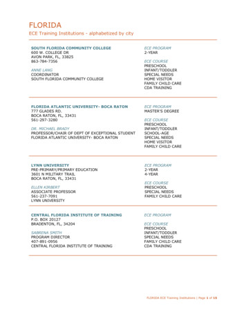
INTRODUCTION Direct Drive FansOptional Fin Guard(top and bottom)OptionalUnit DisconnectNot ShownPC Windows BasedMicrocomputerStandard lar Designwith common componentsthroughout the lineOptional ElectronicExpansion Valves forRemote EvaporatorsThe Dunham-Bush Commitment.Our commitment to continuous product improvement and quality enhancement continues in this newgeneration of Air Cooled Reciprocating Condensing Units.The AUDR-B.New enhanced condenser fins, plus modular construction provide for increased commonality of parts, highunit electrical efficiency, and compact footprint throughout the line. We can build a unit for you in a shorterlead time, while still offering all the optional features mounted, piped and wired to meet your exact needs. Infact, Dunham-Bush is famous for its design flexibility. Our customers find that we can handle specialapplications where others might turn away.AUDR-B units feature state-of-the-art full function, PC Windows based, microcomputer controller standardon all model sizes with an optional tie-in to a building management system. Remote monitoring via optionalmodem allows instant diagnosis by the user or by a skilled Dunham-Bush technician.Upon shipment, the new AUDR-B unit is installation-ready with its compact size, reduced weight, and completefactory piping and wiring.The AUDR-BDelivering on the promise of the Dunham-Bush Commitment2
TABLEOFCONTENTS Page No.Introduction . 2Nomenclature . 3Standard Features . 4Unit FeaturesCompressors . 5 - 6Air Cooled Condensers . 7Remote DX Cooler Module . 7Microcomputer Controller . 8 - 10Options . 11-14Accessories . 15Unit Construction . 15Installation and Application Data . 16 - 19Application Data for Condensing Units with DX Air Handlers . 20Typical Sequence of Operation - For DX Air Handler Applications(RAH-1) Return Air Temperature Control for Constant Air Volume Systems . 21(RAH-2) Leaving Air Temperature Control for Constant or Variable Air Volume Systems . 22(RAH-3) Fresh Air Economizer Control for Constant or Variable Air Volume Systems . 22(RAH-4) 100% Outside Air Temperature Control for Constant or Variable Air Volume Systems . 22(RMAH) Suction Pressure Control with Multiple Evaporator Systems . 23Performance Data . I.P. 24 - 29 . S.I. 30 - 35Application Data for Condensing Units as Split-System Chillers . 36 - 41Typical Sequence of Operation for Split-System Chillers . 37Selection Procedure . 42Remote DX Cooler Module - Water Side Pressure Drop . 43Performance Data for R22 . I.P. 44 - 53 . S.I. 54 - 63Physical Specifications . I.P. 64 - 69 . S.I. 70 - 75Dimensional Data . 76 - 83Electrical Data . 84 - 89Typical Control Wiring Diagram . 90Typical Power Wiring Diagrams . 91 - 92Product Specifications . 93 - 99Installation Clearance . 100NOMENCLATUREA U DRB 100 D AR Z BMicrocomputer ControlAir Cooled CondenserR22 Base RefrigerantCondensing UnitDirect Expansion EvaporatorReciprocating CompressorUnit VintageNominal Capacity in TonsAK 200/208/3/60 Main PowerAN 230/3/60 Main PowerAR 460/3/60 Main PowerAS 575/3/60 Main PowerRefrigerant Circuits(S) Single - 021S, 024S, 027S, 030S, 035S(D) Dual - 030D, 035D, 040D, 045D, 050D052D, 055D, 062D, 070D, 075D080D, 085D, 090D, 100D, 102D112D, 120D, 130D, 140D, 155D170D, 180D, 185D, 190D, 200D3
STANDARD FEATURES Size Range 30 Models from 24 to 224 Tons High Unit EER at ARI Standard Conditions Rated with HCFC-22. Compatible with HFC’s (R-407C and R-134a)using Synthetic Oil (Consult Factory)Compressor Reliable Semi-Hermetic Reciprocating Type at 1750 RPM(2) Independent Refrigerant Circuits over 30 Tons for RedundancyUnloading Compressor under 85 Tons for Energy SavingsCompressor Cycling of 4 compressors over 85 Tons for Maximum EfficiencyOptional capacity control steps available over 45 tonsEvaporator Control Modes of Operation Optional Split-System Chiller—Remote Cooler Module RCH1—Standard Cooler Module for 44 F Leaving Water TemperatureRCH2—Oversized Cooler Module for 42 F Leaving Water Temperature when requiredRCH3—Oversized Cooler Module for 40 F Leaving Water Temperature when requiredASME/CRN Stamped on all SizesDB High Efficiency Inner Fin Design for Compactness and Weight ReductionMinimum of 250 PSIG Refrigerant Side Design Pressure200 PSIG Water Side Design Pressure Optional DX Air Handler Control Modes of Operation RAH1—DX Air handler with Return Air Control, Constant Volume Control Systems with less than 30%Outside AirRAH2—DX Air handler with Leaving Air Control, for Constant or Variable Air Volume Systems with lessthan 30% Outside AirRAH3—DX Air Handler with Fresh Air Economizer with Leaving Air Control, for Constant or VariableVolume Systems with up to 100% Outside AirRAH4—DX Air handler with 100% Outside Air with Leaving Air Control for Constant or Variable AirVolume Systems with Hot Gas Bypass required and ECCS required when availableRMAH—DX Multiple Air handlers with Suction Pressure Control Requires Customer Contact Closure(s)Call for CoolingCondenser Long Life Copper Tubes with Aluminum FinsIntegral Sub-Cooling Circuit for Maximum Efficiency450 PSIG Test PressureLow Noise 30" Diameter Fans - Direct Drive at 1140 RPMAll Fan Motors Open Drip Proof with Rain Shield for Safety and Low MaintenanceMinimum Clearance Required on Sizes 021S to 035SElectrical/Control Widest range of optional equipment available Proactive Full Function PC Windows Based Microcomputer Controller on all Sizes forPrecise Control and Maximum Efficiency Separate Power and Control Panels for Service on Dual Circuit Units Models 030D-200D Separate Power and Control Compartments on Single Circuit Units Models 021S to 035S ETL/CSA Unit Approval (IEC Control Panel Available) MEA Unit Approval4
UNIT FEATURES: COMPRESSORS Recent advances in materials technology have beenincorporated into these compressors to allow the mostefficient package chillers and condensing units availabletoday. All compressors are semi-hermetic so that aminor part replacement job doesn’t become acompressor replacement job. The number ofcompressors on a specific package may be found inthe physical specifications on pages 64 thru 75.Rugged - designed for heavy duty refrigeration andair conditioning use, these compressors featurehousing, heads and end bells of high strength cast iron.Oversize crankcases to assure proper lubrication andcooling for running gear are incorporated into thehousing.Lightly stressed bearing surfaces are made possibleby the use of smaller diameter pistons and largerbearing surfaces.Radiographic X-ray quality, permanent mold castaluminum connecting rods have a high strength toweight ratio and superior bearing qualities.A large capacity built-in suction filter is locatedbetween the suction service valve and the motor toprevent abrasive material such as flux, dirt, scale ormetal chips from entering the motor cavity. Theabrasive action of this foreign material would crack,chip and wear away the motor insulation which couldcause premature motor failure. These same abrasivescould also cause bearing seizures and excessive wearof all surfaces.Discharge and suction valves are also provided for easeof service.A lubrication system is an integral part of all thesecompressors. Positive pump lubrication systems areused on the compressors. Increased oil flow in additionto increased lubrication assists in dissipating heatgenerated by the higher bearing loads. The pump islocated in the end bell and is driven by the crankshaft.Oil is picked up through a strainer in the crankcaseand discharged under pressure through drilledpassageways in the main bearings.Quiet - Enlarged areas in the muffler type cylinderheads provide a chamber to reduce the velocity of themixing discharge gases from each discharge stroke.This dampens discharge line pulsations by smoothingout flow velocities.Vibration-free - Discharge line mufflers, solid mountedcompressors, statically and dynamically balancedcrankshafts and motors insure vibration-free, quietrunning compressors.Dependable - Years of experience have developedheavy-duty motor windings, incorporating cooling byfull refrigerant flow through the motor. Insulationsystems exceed Class B requirements and overloadprotection is accomplished by a solid state motormodule with winding temperature thermistor input.5
All compressors also feature individual suction and discharge, manually operated, service valves, oil sightglasses and cartridge type crankcase heaters.Capacity Control - Modulation of capacity in responseto system load requirements is affected by amicrocomputer sequence controller which monitors thereturn or leaving air temperature for DX Air Handlersor leaving water temperature on split-system chillerapplications.Compressors are controlled via cylinder unloading andoptional hot gas bypass. Cylinder unloading is achievedby shutting off the suction gas supply to one or morecylinder banks resulting in good partload efficiencies.Hot gas bypass operates by imposing an artificial loadon the evaporator. Discharge gas from the compressorTABLE 130D140D155D170D180D185D190D200Dis introduced to the liquid-vapor mixture of refrigerantdownstream of the expansion valve. The dischargegas is cooled by the liquid refrigerant present in theturbulence of the evaporator so that the finaltemperature of refrigerant gas leaving the evaporatordoes not rise. Hot gas bypass does not offer any energysavings, but does allow the cooling capacity of theequipment to vary precisely with the load requirements.On multiple compressor units, capacity is controlledby a combination of cylinder unloading and compressor staging. See the following table for the type ofcapacity control furnished as standard with each unit.All compressors are UL recognized and C.S.A. approvedfor 60 Hz.Package Capacity Control Steps% Full Load Capacity ControlStandardOption Capacity Control Steps(and Optional HGBP)(and Optional HGBP)100 - 50 - (25) - OFF100 - 50 - (25) - OFF100 - 67 - 33 - (17) - OFF100 - 67 - 33 - (17) - OFF100 - 67 - 33 - (17) - OFF100 - 75 - 50 - 25 - (13) - OFF100 - 75 - 50 - 25 - (13) - OFF100 - 75 - 50 - 25 - (13) - OFF100 - 80 - 42 - 21 - (12) - OFF100 - 80 - 59 - 42 - 21 - (12) - OFF100 - 82 - 47 - 23 - (12) - OFF100 - 82 - 59 - 47 - 23 - (12) - OFF100 - 83 - 50 - 33 - (17) - OFF100 - 83 - 67 - 50 - 33 - 17 - (9) - OFF100 - 82 - 54 - 36 - (18) - OFF100 - 82 - 64 - 54 - 36 - 18 - (9) - OFF100 - 83 - 50 - 33 - (17) - OFF100 - 83 - 67 - 50 - 33 - 17 - (9) - OFF100 - 83 - 50 - 33 - (17) - OFF100 - 83 - 67 - 50 - 33 - 17 - (9) - OFF100 - 85 - 46 - 31 - (16) - OFF100 - 85 - 69 - 46 - 31 - 15 - (8) - OFF100 - 75 - 50 - 25 - (13) - OFF100 - 88 - 75 - 50 - 38 - 25 - (13) - OFF100 - 77 - 50 - 27 - (14) - OFF100 - 89 - 77 - 64 - 50 - 37 - 27 - (14) - OFF100 - 78 - 50 - 28 - (14) - OFF100 - 90 - 78 - 69 - 50 - 40 - 28 - 19 - (10) - OFF100 - 77 - 50 - 27 - (15) - OFF100 - 91 - 77 - 68 - 50 - 41 - 27 - 18 - (9) - OFF100 - 75 - 50 - 25 - (13) - OFF100 - 92 - 75 - 67 - 50 - 42 - 25 - 17 - (9) - OFF100 - 77 - 50 - 27 - (14) - OFF100 - 91 - 77 - 68 - 50 - 41 - 27 - 18 - (9) - OFF100 - 75 - 50 - 25 - (13) - OFF100 - 92 - 75 - 67 - 50 - 42 - 25 - 17 - (9) - OFF100 - 76 - 50 - 26 - (13) - OFF100 - 91 - 76 - 68 - 50 - 41 - 26 - 18 - (9) - OFF100 - 75 - 50 - 25 - (13) - OFF100 - 92 - 75 - 67 - 50 - 42 - 25 - 17 - (9) - OFF100 - 73 - 50 - 23 - (12) - OFF100 - 92 - 73 - 65 - 50 - 42 - 23 - (12) - OFF100 - 75 - 50 - 25 - (13) - OFF100 - 88 - 75 - 63 - 50 - 38 - 25 - (13) - OFF100 - 73 - 50 - 23 - (12) - OFF100 - 89 - 73 - 62 - 50 - 39 - 23 - (12) - OFF100 - 73 - 50 - 23 - (12) - OFF100 - 89 - 73 - 62 - 50 - 39 - 23 - (12) - OFF100 - 75 - 50 - 25 - (13) - OFF100 - 88 - 75 - 63 - 50 - 38 - 25 - (13) - OFF100 - 75 - 50 - 25 - (13) - OFF100 - 88 - 75 - 63 - 50 - 38 - 25 - (13) - OFFNOTES: 1 - Sizes 021S - 080D have cylinder unloading on lead compressor only(Extra steps shaded)2 - Sizes 085D - 200D have compressor staging standard3 - Sizes 045D - 200D cylinder unloading for optional extra unloading steps of capacity controlThis ECCS option is not available on AUDR-B 052D - 075D if “ACM” option is ordered (page 12)4 - HGBP Hot Gas Bypass available on lead compressor only, all units5 - HGBP modulates to approximately one half of the preceding unloaded stepEXAMPLE: AUDR-B 070 w/HGBP (33% x .5 17% minimum capacity)EXAMPLE: AUDR-B 070 w/optional steps and optional HGBP (17% x .5 9% minimum capacity)6
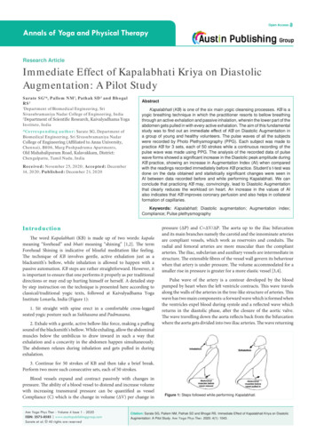
UNIT FEATURES: AIR COOLED CONDENSERSAll units have direct drive propeller fans and motorswith individual fan sections providing superior headpressure control. Close blade tip clearance with the fanventuri assure smooth, quiet operation. See theelectrical data for information on motor specifications.All air cooled condensers are formed of 3/8 inchdiameter copper tubes mechanically expanded intoaluminum fins for maximum efficiency of heat transferbetween the circulating refrigerant and air. The finshave full self-spacing collars which completely covereach tube. The staggered tube design improves thethermal efficiency of the coil and eliminates bypassingof air around the tubes. The return bends, headersand nipples are all copper, sized for minimum pressuredrop, brazed with inert gas in the tubes and tested afterfabrication to 450 psig. A separate subcooling circuit is standard on all units tomaximize energy efficiency.Partitions separate each fan section to eliminate possibleback spin. Two different fans cover the entire line andfan cycling control is supplied as standard. This lowersthe minimum ambient temperature at which thepackaged equipment will effectively start and operate.For lower ambient requirements than standard, variablespeed options are available.All cabinetry is heavy gauge galvanized steelconstruction with aluminum tube sheets. The UnitControl Center, end enclosure panels, and fan deckingshall be constructed of 16 gauge galvanized steel andbe finished with a baked powder high grade outdoorquality coating system which exceeds 500 hour saltspray requirements when tested in accordance with theASTM-B-117 specifications.UNIT FEATURES: OPTIONAL REMOTE DX COOLER MODULE FORSPLIT-SYSTEM CHILLERSWater CoolersThe water coolers employ the most advanced vesseltechnology available today, including the patentedInner-Fin construction of the CH and EX coolers. Allvessels 5 inches in diameter are U.L. listed. Larger vesselsare designed and constructed to meet the requirementsof the ASME Code, Section VIII, Division 1 for unfiredpressure vessels and are stamped accordingly.The CH model coolers have 1/2 inch diameter coppertubes brazed into tubesheets. The shells are constructedFLUID INRETURN WATERBULB WELLFREEZE STATBULB WELLof steel and the entire assembly is welded and brazedfor the best cost effectiveness possible. The EX coolersincorporate 5/8 inch rolled tubes and removable headsfor ease of tube maintenance. Vent and drain connections are included on all vessels.See Table 7 below for appropriate pressure ratings, Table43 for connection sizes, pressure drop curves and minimum/maximum flow rates.FLUID OUT"SEE PHYSICAL SPEC'SFOR CONNECTION SIZES"INTERNAL WATER BAFFLESREFRIGERANTINREFRIGERANTOUTWATER FLOW PATHVENT AND DRAINFLUID INSEE SECTION A-AFLUID OUTRETURN WATERBULB WELLFREEZE STATBULB WELL"SEE PHYSICAL SPEC'SFOR CONNECTION SIZES"INTERNAL WATER BAFFLESREFRIGERANTINREFRIGERANTOUTREMOVEABLE HEADSBOTH ENDSWATER FLOW PATHVENT AND DRAINSECTION A-APATENTED INNER-FINCONSTRUCTIONTABLE 7Shell & TubeHeat ExchangerWater CoolerCHEXWater SideDesign PressureTest Pressure(PSIG) (kPa)(PSIG) (kPa)200 (1379)200 (1379)300 (2068)300 (2068)Refrigerant SideDesign PressureTest Pressure(PSIG) (kPa)(PSIG) (kPa)300 (2068)250 (1724)375 (2586)312 (2151)7
WINDOWS BASED MICROCOMPUTER CONTROLLER DIRECTORFull FunctionWindows BasedMicrocomputerControllerComplimenting our high-energy efficient product is aFull Function Microcomputer Controller designed tokeep your system running at its most Energy EfficientLevel, based on current load.This system is designed as a Control ‘State’ (controlstatus) microcomputer providing the user with the current Control State for exact knowledge of what themicrocomputer is doing. Some of the main featuresof the controller are as follows: A large character LCD display that can be seen inbright or dim lighting. A 16 function keypad that is so user friendly it rarelyrequires a manual. A PC control programming download/pullback inonly 45 seconds. Alarm information is provided in simple English forthe previous 32 alarms, with data shown down tothe second. The system provides ‘last time’ enabled & disabled,number cycles, and total run hours. A slope algorithm control function with all analogs read 10 times per second provides unparalleled stability. A ‘fuzzy logic control zone’ based on leaving fluidtemperature that reduces compressor cycling, andimproves unit part load efficiency. A proactive compressor protection logic for protecting against low or high discharge pressure tominimize compressor cycling and nuisance trips. A four-layer printed circuit board provides extremely high quality and unit control stability. A battery backed up Real Time Clock that shouldnever need attention. An automatic power monitoring system that is designed to protect your system. A Windows based display providing all pertinentinformation on your ‘PC’. Multiple authorization levels to provide completesecurity of the control system. Automatic history storage that provides data to aflexible static and dynamic graphing system.A high speed RS232 port operating at 19,200 baudfor connection to a local PC up to 100 feet awayor a modem at 14,400 baud rate communicationsfor remote communication. Extended temperature range to allow operation ineither hot or cold climates, from -40 F (-40 C) to140 F (60 C).A high speed RS485 port for connection to a building management system, or PC at 38,400 baud ratecommunications up to 6000 feet away from thechiller(s).8
Display InformationCapacity ControlAll information is displayed using common terms thatare easy to understand. It is a simple procedure todetermine the actual status of the system and theindividual circuits, as they are displayed in commonterms that are meaningful. The 2 line by 16 extra largecharacter alphanumeric liquid crystal display (LCD)utilizes easy to understand menu-driven software. TheLCD displays eight character alphanumeric sensornames and twelve character alphanumeric set pointnames enabling the use of meaningful status names.This enables an inexperienced operator to quickly workthrough these menus to obtain the information theyrequire or to modify control parameters. The welldesigned keypad is separated into a DISPLAY STATUSsection and an ENTRY section each consisting of eightkeys that are clearly labeled to identify the informationthat will be displayed. When data is being modified,the second display line contains help information toensure that the desired modification is properly made.Easily accessible measurements include:Control is based upon entering or leaving airtemperature when used with DX air handler or leavingchilled water temperature for split-system chillers. Howfast the temperature is changing and the rate of changeare calculated and capacity decisions are based uponthe rate, the current temperature, and the controltemperature zone. Capacity is never added if the systemis moving toward the temperature target at anacceptable rate. The unit will monitor all controlfunctions and load the compressors to the requiredoperating capacity. Remote adjustment of the enteringor leaving air temperature or leaving chilled watertemperature setpoint is accomplished through eitherdirect connection or a remote keypad to themicrocomputer through the RS485 long distancedifferential communications port, via PC or a modemconnected to the RS232 communication port, or froman external Building Automation System supplying asimple 0 to 5 VDC signal. Current capacity statusCurrent circuit/compressor statusEntering and leaving chilled water temperatureon optional remote cooler moduleEvaporator pressure of each refrigerant circuitCondenser pressure of each refrigerant circuitCompressor elapsed run time, each compressorNumber of compressor startsCompressor contactor status with actual Amp drawFan on/off status(Remote chilled water reset input optional for remote cooler module)(Optional air or water flow switch status)External start/stop command status(Optional low ambient temperature sensor foreasier cold ambient starting)(Optional low ambient lockout)Two proactive control features included in themicrocomputer are low suction and high dischargepressure unload. Compressor #1 will be unloaded ifcircuit #1 discharge pressure exceeds the high pressureunload setpoint or if suction pressure from eitherrefrigerant circuit approaches the low-pressure tripsetpoint. If there is more than one compressor on arefrigerant circuit, one of the compressors will be shutdown under one of these “near-fault” conditions.System ControlThe unit may be started or stopped manually, orthrough the use of an external signal from a BuildingAutomation System. In addition, the microcomputermay be programmed with a seven-day optional cycleor other DB control packages may start and stop thesystem through interconnecting wiring.System ProtectionThe following system protection controls willautomatically act to insure system reliability: Low suction pressureHigh discharge pressureHigh motor temperature/over currentFreeze protection (optional Remote Cooler Module)Compressor run errorLow oil pressurePower loss(Optional remote cooler module chilled waterflow loss)Sensor error(Pump down frequency alarm with no chiller flow)Anti-recycleTime delay9
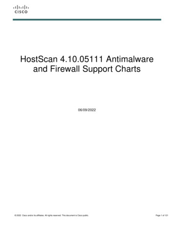
Remote MonitoringThe Microcomputer is equipped with a high speed RS232 communications port and two high speed RS485 communications ports, to allow for a variety of different remote monitoring operations. The RS232 communicationsport allows for remote communications at distances of up to 100 feet over a 4-wire shielded cable. The RS485communication system allows for remote communications at up to 6000 feet with a 2-wire shielded cable connection.1) RMCT - Remote Mounted Control Terminal (Figure 10A)This Remote Mounted Control Terminal (RMCT) is a stand alone Control Terminal to communicate and controlthe unit from a remote location up to 6000 feet away, via the 485 communications port, when wired with a2-wire shielded cable. This enhanced version of the Remote Mounted Control Terminal with 8 relay outputsand 8 sensor inputs provides remote alarm capabilities and additional sensor inputs as may be required.Figure 10ADB DIRECTORREMOTE CONTROLTERMINALRS485 — UP TO 6000 FEET AWAY DB DIRECTORUNITCONTROLLERRMCT - MCS8REMOTE MOUNTEDCONTROL TERMINALRS232 PORT AVAILABLE FORLOCAL PC OR EXTENDEDDISTANCE THROUGH A MODEM2) PCON - PC Connection:The PC Connection function provides communications for complete operation of the packaged chiller including graphing information. This option is available through two communications techniques as follows:a) PCCB (Basic) (Figure 10B)The standard communications for PCCB is via the RS232 connection which may be as far as 100 feet awayfrom the packaged chiller.Figure 10BLocal PC withWindows & PC-CONNDB DIRECTORUNITCONTROLLERRS232 — UP TO 100 FEET AWAYb) PCCE (Enhanced) (Figure 10C)The enhanced PCCE system allows for communications via the RS485 port and can be located as far as6000 feet from the packaged chiller(s). This option requires the addition of a gateway to convert theRS485 port back to a RS232 port and then may be connected to a modem or directly to a PC. Oneadditional feature is that you may field install a manual AB switch, which allows switching between a localPC and a modem.Local PC withWindows & PC-CONNFigure 10CDB DIRECTORUNITCONTROLLERDB DIRECTORUNITCONTROLLERRS485DB DIRECTORUNITCONTROLLERRS485RS485MSC 485GATEWAYAs can be seen, the microcomputer system allows for a variety of remote connection capabilities for almost infiniteflexibility. Utilizing the PC connection portion of the system, the unit will support up to twenty packaged chillersconnected via the RS485/RS232 ports into the system. The user may then select whichever packaged chiller to review.1010
OPTIONS Options are installed at the factory. Accessoriesare shipped unmounted.Copper Fin Condenser (CUF) - Copper fin andtube condenser.Poly fin Condenser (PFC) - The material is a polyester paint baked onto the aluminum finstock prior tofinal manufacture, rather than material applied to theassembly after formation of the coils. The pre-paintedfin material has been tested for salt spray corrosionresistance using ASTM B117 specification.AUDR-B EVAPORATOR CONTROL MODES OFOPERATION (Select only one out of the eight AUDRB Control Modes of Operation shown below)“Split-System Chiller” Application Options:If HGBP is required, it must be ordered for eachcircuit. Interlaced evaporator coil circuiting isrequired.Stacked Coils must have interlaced coil circuitryfor each coil-in-face. The entire coil face areamust be activated on the first step of cooling toeliminate by-pass air operation.6. RAH3 - DX Air Handler with Fresh Air Economizer, Leaving Air Temperature Sensing for Constant or Variable Air Volume Controlled Systems.The outside air quantity can be up to 100% depending on the customer control of the economizer. Entering Air Enthalpy will be used to disable the unit below a set-point enthalpy, typically (25.0h).(Select only one out of three “RCH” Modes shown below)Extra steps of capacity control (ECCS) are recommended for variable air volume systems.The ratings in the Catalog Performance Tables for SplitSystem Chillers require specific “RCH” Cooler Moduleslisted below:If HGBP is required, it must be ordered for eachcircuit. Interlaced evaporator coil circuiting isrequired. Stacked coils must have interlacedcircuitry for each coil-in-face. The entire coilface area must be activated on the first step ofcooling to eliminate by pass air operation.1. RCH1 - Standard Cooler Module - for 44 F(6.5 C) leaving water temperature.2. RCH2 - Oversized Cooler Module - for 42 F(5.5 C) leaving water temperature. This is required for water applications on ModelsAU
Delivering on the promise of the Dunham-Bush Commitment Direct Drive Fans Optional Unit Disconnect Not Shown Semi-Hermetic Reciprocating Compressors PC Windows Based Microcomputer Standard All . Application Data for Condensing Units with DX Air Handlers .20 Typical Sequence of Operation - For DX Air Handler Applications (RAH-1) Return .