Transcription
Department of Public WorksAdministration – Development Services - Engineering – TrafficSolid Waste Management – Road & Bridge – RTPO – Fleet200 S. Spruce Street P.O. Box 20,000 Grand Junction, Colorado 81501Phone (970) 244-176545.5 MP 0.6 Road Improvement Project (IFB-18-03106) Addendum #1September 17, 2018Please provide a soils report for information concerning the rock dowel drilling.The final geotechnical report will be included as part of this addendum.Please review the length of the rock dowel. I came up with almost 800LF after taking into considerationthe length of embedment, length in concrete foundation, and length in concrete fill.Your question prompted a review of the formula used to determine this quantity, and you’recorrect, the required length is higher than what was issued in the bid quantities. The totalrock anchor quantity is approximately 940 linear feet. A revised bid schedule is included withthis addendum.Can the sacrificial rock dowel tests be performed in tension?Yes.What is the design load of the rock dowels?The design capacity of a grouted #6 all-thread rock dowel is approximately 4.5 kips per linearfoot of embedment in competent sandstone bedrock. This is based on presumptive ultimatebond strengths and resistance factors published by AASHTO, and will need to be field-verifiedby the sacrificial load testing.Are the rock dowels to have corrosion protection and if so what kind?No further corrosion protection measures have been recommended as the threaded rods willbe fully encased in grout and concrete, and the PVC centralizers are meant to keep the dowelscentered in the grout body to provide equal cover.On sheet D-2 2” OD washers are specified for the rock dowels. Typical washers for #6 bar are 1.75” OD.Are 1.75” OD washers acceptable?2” O.D. washers are preferable to develop better anchorage in the concrete footing withgreater pullout resistance. That being said, our calculations did not indicate that a 2” washer isabsolutely necessary, so if there is a considerable cost savings, the 1.75” O.D. washers areacceptable.
Department of Public WorksAdministration – Development Services - Engineering – TrafficSolid Waste Management – Road & Bridge – RTPO – Fleet200 S. Spruce Street P.O. Box 20,000 Grand Junction, Colorado 81501Phone (970) 244-1765The grout for the grouted riprap is to be per CDOT specification 507.05. Paragraph 507.04 says “Mortarshall be used within 45 minutes after mixing and shall not be re-tempered.” Typical delivery times aftermixing to actual placement are over 75 minutes at the job site. Please review and consider allowing theuse of retarder.Paragraph 507.04 relates to a separate specification. The mortar for the grouted riprap shouldconform to requirements in Paragraph 507.05. Delivery times for batched concrete and mortarshould not exceed 90 minutes per ACI requirements. If necessary, a retarder is allowed,subject to engineer review and approval.Who is responsible for testing of the riprap grout and or the rock dowel grout?DOWL will provide testing of the riprap mortar as well as the grout for the rock dowels.
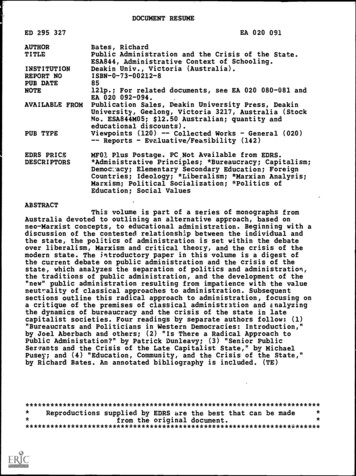
45.5 ROAD (MP 0.6) BID SET - SUMMARY OF QUANTITIES (ADDENDUM DESCRIPTIONUNITQUANTITYCLEARING AND GRUBBINGREMOVAL OF ASPHALT MAT (PLANING) (2" DEPTH)UNCLASSIFIED EXCAVATION (COMPLETE IN PLACE)STRUCTURE BACKFILL (CLASS 1)EROSION CONTROLAGGREGATE BASE COURSE (CLASS 6)HOT MIX ASPHALT (GRADING SX) (PG 64-22) (2 INCH)HOT MIX ASPHALT (GRADING SX) (PG 64-22) (4 INCH)GEOTEXTILE (SEPARATOR) (MIRAFI 180N)GEOTEXTILE (REINFORCEMENT) (MIRAGRID 5XT)TOE WALLGABION WALLROCK DOWELHILFIKER SPIRALNAILRIPRAP (D50 24 INCH) (FURNISH ONLY)GROUTED RIPRAP (D50 24-INCH)CONCRETE FILL BELOW TOE WALL (CDOT CLASS D)CONCRETE COLLARS AT CULVERT EXTENSION (CDOT CLASS D)REINFORCING STEEL12" CMP CULVERT EXTENSIONGUARDRAIL TYPE 3 (6'-3" POST SPACING) (7' STEEL POSTS) (31 INCH MGS)END ANCHORAGE TYPE SRT (31 INCH MGS)END ANCHORAGE TYPE SKT (31 INCH MGS)SANITARY FACILITIESCONSTRUCTION SURVEYINGMOBILIZATIONPUBLIC INFORMATION SERVICESPAVEMENT MARKING PAINT (WHITE)VARIABLE MESSAGE SIGN (TWO)TRAFFIC CONTROLF/A MINOR CONTRACT 110711
Office LocationsALASKAFINAL GEOTECHNICAL rMESA COUNTY45.5 ROAD IMPROVEMENTS(MP 0.6)MESA, COLORADOARIZONATempeTucsonCOLORADOAugust 27, 2018DenverMontroseGrand JunctionMONTANABillingsBozemanButteGreat FallsHelenaMiles INGGilletteLanderLaramieSheridanPrepared for:Keith LayMesa County Public WorksP.O. Box 20,000Grand Junction, CO 81502
TABLE OF CONTENTSIntroduction. 1Site Conditions . 1Geology. 2Geologic Hazards . 24.1Runoff & Erosion. 24.2Flooding/Debris Flows . 34.3Rockfall . 3Soil Characteristics . 45.1Field Evaluation . 45.2Laboratory testing . 55.3Soils Summary . 6Engineering Analysis. 66.1Pavement Design . 66.1.1ESAL Calculation . 66.1.2Subgrade Support Characteristics . 76.1.3Pavement Section Selection . 86.2Retaining Wall Global Stability Analysis . 96.2.1 Assumed Soil Strength Parameters .106.2.2 Global Stability Summary .10Recommendations .117.1General Design Criteria .117.2Seismic Design Criteria .127.3Retaining Wall Foundations .127.4Retaining Structures .137.5Site Preparation and Grading .147.6Concrete .157.7Excavation and Shoring .167.8Pavement Section Design .17References .18Closing Considerations .189.1Standard of Care and Interpretation of Subsurface Data.189.2Use of This Report .189.3Retention of Samples .19Additional Services .19Mesa County 45.5 Road Improvements MP0.6 FINAL geotech report.docxProject #7122.74818.01Page i
APPENDIX A - Project Maps . AAPPENDIX B - Borehole Logs. BAPPENDIX C - Laboratory Results . CAPPENDIX D – Engineering Analysis . DMesa County 45.5 Road Improvements MP0.6 FINAL geotech report.docxProject #7122.74818.01Page ii
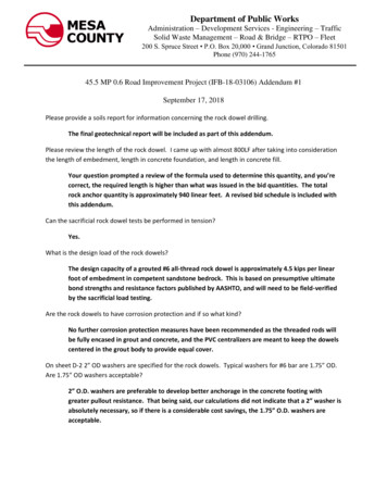
INTRODUCTIONDOWL conducted an evaluation of subsurface and site conditions on January 17 and 31, 2018along a 0.4-mile section of the southern end of 45.5 Road (aka DeBeque Cutoff) in MesaCounty. Our services were performed as requested by Mesa County Public Works to analyze anddesign bank stabilization of the roadway to improve the safety and performance of the road.Atwell Gulch is actively undercutting the embankment supporting the road on the east side andthere are sections with little to no shoulder and there is a drop-off into the drainage. Retainingwalls, guardrails and other features will be necessary to protect the road from further erosionand to provide a safer roadway. To design these improvements, the geotechnical evaluation forthis project consisted of a site reconnaissance, drilling of eight boreholes, logging and testing ofrepresentative materials found, slope stability analysis, and preparation of this report.SITE CONDITIONSThe project area is on 45.5 Road, 0.6 miles north of the junction of Highways 65 and 330,which is about 2 miles north of the town of Mesa and 10 miles east of I-70 (see Vicinity Map,Map 1, Appendix A). As seen on the Site Plan (Map 2, Appendix A), this segment of road isbetween two larger pull-outs on the east side of 45.5 Road. Atwell Gulch cuts the toe of theroad embankment fill in this area. Atwell Gulch is shown in blue on the Site Plan and erosion ofthe embankment is especially severe near boreholes BH#1, BH#3, and BH#4 at the north endof this segment and near BH#6 and BH#7 at the south end. The following photographs weretaken of the site at the time of our field evaluation.Photo 1 (left) is a view north at the northern portion of the project area with AtwellGulch to the right. Photo 2 (right) is a view south at this same area. Note the lack ofroad shoulder and the erosion occurring of the road edge.A total of eight boreholes were drilled at this site with four holes augered near the road inembankment or native soils (BH#1, BH#2, BH#7, BH#8) and four holes cored into thestreambed of Atwell Gulch (BH#3 - BH#6), as indicated on the Site Plan. The results of our fieldand laboratory testing are discussed in the Soil Characteristics Section of this report.Mesa County 45.5 Road Improvements MP0.6 FINAL geotech report.docxProject #7122.74818.01Page 1 of 19
GEOLOGYThe project site is in a relatively remote area between the Colorado River and Plateau Creek.The landscape is characterized by rounded sandstone ledges, sloping benches, sideslopesmantled with rockfall and slopewash debris, and an array of geological hazards includingrockfall, flash floods, and mudflows. According to the Preliminary Geologic Map of the MesaQuadrangle (Donnell et al, 1984), this section of 45.5 Road crosses the Ohio Creek Member andlower part of the Mesaverde Formation. Collectively, the bedrock sequence is characterized byhighly weathered, white or yellow to brown kaolinitic sandstone interbedded with some pebblysandstone, siltstone, and shale. Some thin coal beds and carbonaceous shale can be found inthe lower part of the Mesaverde Formation in this region. Incision by drainages is active andon-going and the terrain is highly dissected due to the weakly cemented, fractured, and highlyweathered nature of the bedrock. The following photographs illustrate the nature of thebedrock at this site.Photo 3 (left) is a view to the north at the outcrops north and east of Atwell Gulch asBH#1 was being drilled. Photo 4 (right) is a view of the rock outcrop near BH#8 on thewest side of 45.5 Road. Note the irregular, benched and weathered nature of this rock.GEOLOGIC HAZARDSThis section of the report is included so that Mesa County is aware that construction in the areacomes with certain risks. Some structures and roadways in the region have experiencednegative impacts due to slope movement, sensitive soils, and geologic hazards. Althoughaccepted engineering practice for design and construction can reduce the potential forundesirable performance due to challenging climate and soil conditions, almost every structureis subject to at least some degree of potential risk. These risks are discussed below.4.1Runoff & ErosionSurface runoff from rainfall and snowmelt drains as sheetflow across the surrounding slopesand existing roadway, and larger events are carried by Atwell Gulch and many micro-drainagesthat are tributary to this arroyo. This drainage carries smaller runoff events as well as largeMesa County 45.5 Road Improvements MP0.6 FINAL geotech report.docxProject #7122.74818.01Page 2 of 19
flash floods that, as indicated by Mesa County Public Works, have over-topped the roadway inthis area. High velocity runoff can erode surface sediments and scour channel walls, causingwidening and/or down-cutting of drainages. Vegetation in the area consists of junipers,rabbitbrush, and other native high desert plants. This sparse vegetation does not provideuniform protective cover from erosion as evidenced by many small rills and gullies in the loose,soft soils and weathered sandstone. Protecting these soils from erosion near the roadway andwalls both during and after construction will be important to reduce soil loss and roaddegradation over time.4.2Flooding/Debris FlowsThe Atwell Gulch channel is dry for much of the year, but can carry large volumes of water inflash flood events. These flood events also carry muddy debris consisting of rocks, vegetation,and other loose materials picked by running water. The following photographs show the natureof the channel in Atwell Gulch.Photo 5 (left) is a view to the north at Atwell Gulch as BH#3 was being drilled. Notethe muddy and rocky sediment in the channel in this straight section of the arroyo.Photo 6 (right) is a view of the channel downstream of BH#5 where the stream hascut into sandstone bedrock.4.3RockfallGiven the uneven, weathered, and benched nature of the sandstone bedrock in this area, thereis potential for rockfall. As seen on the Site Plan, 45.5 Road hugs a rock outcrop on the westside of this road segment between BH#2 and BH#6. However, rockfall hazard from this areacurrently appears minimal due to the nature of the rock outcrops and distance from theroadway. Since no road widening on the west side of 45.5 Road is proposed with theimprovements, there is no increased risk from rockfall hazards and no mitigation is necessary.Other geologic hazards are not known to be present near this segment of 45.5 Road.Mesa County 45.5 Road Improvements MP0.6 FINAL geotech report.docxProject #7122.74818.01Page 3 of 19
SOIL CHARACTERISTICS5.1Field EvaluationA total of eight boreholes were drilled at this site using a tracked CME 55 rig, with four holesaugered near the road in embankment or native soils (BH#1, BH#2, BH#7, BH#8) and fourholes cored into the streambed of Atwell Gulch (BH#3 - BH#6), as indicated on the Site Plan(Appendix A). The locations of the borings were selected to evaluate the soils for retaining walldesign, determination of slope stability, and pavement design. The boreholes were drilled with a4-inch solid stem continuous flight auger for the roadway embankment soils and HQ core barrelwas used for coring in the streambed. Soil samples were obtained at discrete depths bywithdrawing the 4-inch drill string and inserting a standard 1.375-inch inside diameter (I.D.)split-spoon sampler without liners to perform in-situ Standard Penetration Tests (SPTs) ingeneral accordance with ASTM Standard D-1586. The number of blows required to drive thesampler 12 inches in 6-inch increments were recorded (SPT “N” penetration resistance values)and, when properly evaluated, indicate the relative density or consistency of the soils. For thecoring, upon reaching sandstone, the center drill string was removed and a HQ wireline coringassembly was lowered into the hole. Five-foot-long continuous core samples were retrieved asthe coring assembly progressed into the sandstone.The soil, bedrock, and groundwater conditions were logged and the borehole and core logs arepresented in Appendix B. Representative samples of soil and rock materials were tested in ourlaboratory with the results presented in Appendix C. Our embankment augered boreholesreached depths of 19.2 to 24.3 feet and the streambed cores reached depths of 5 to 14 feet.Our findings and recommendations are based on materials found within these depths and soilconditions may change between boreholes and below these depths. The following photographswere taken of the native soil and rock retrieved from BH#4, BH#5, and BH#8.Photo 4 (left) shows the soils collected from BH#8 at 19-20.5 feet, which isrepresentative of the slope colluvium and weathered bedrock of the area. Photo 5(right) shows the cores of sandstone from BH#4 (top) and BH#5 (bottom), which aretypical of the bedded nature of the sandstone in the bed of the drainage.In the embankment boreholes (BH#1, BH#2, BH#7, BH#8) we found light brown, tan to white,dry, moderately dense to very dense, silty to clayey sand with gravel and some cobbles. Ofthese four holes, all were dry except for BH#7, where a seep was recorded at a depth of 14Mesa County 45.5 Road Improvements MP0.6 FINAL geotech report.docxProject #7122.74818.01Page 4 of 19
feet. N-values of 10 blows per foot (bpf) to greater than 50 bpf were recorded in this colluviumand slope alluvium. The variability in density was due to the variable amount of rock within thesoil matrix. Weathered and poorly cemented sandstone was found underlying the colluvium at adepth of 9 to 22 feet at the north end of the study area and 14 feet at the south end.In the streambed cores (BH#3 – BH#6) we found variable amounts of alluvial gravels andsandstone fragments overlying sandstone bedrock of the Mesaverde Formation. This rock is atan, white, light brown to light green, poorly cemented, kaolinitic sandstone with some pebbleconglomerate. As seen in the core logs (Appendix B), total core recovery (TCR) was excellent(86-100%) and Rock Quality Designation (RQD) ranged from 0% to 95%, which is a measureof core segments greater than 4 inches. High-quality rock has an RQD of more than 75% andlow-quality rock has an RQD of less than 50%. In general, the core runs from BH#3 (includingsample CS1) and BH#4 (sample CS2) were higher quality than the core runs from BH#5(sample CS3) and BH#6. The core logs show that the fracture orientation, count, and typeindicate mostly bedding related (low angle) fractures with a Strength Index of R2 to R3 andWeathering Index of W1 to W2. In addition to the weak cementation and bedding structure,discontinuities caused by pebbles and joints added to the variable nature of the sandstonebedrock.Existing road sections were exposed with a shovel and measured at three locations:1. At the north end of the segment uphill of BH#3 – 6-inches of asphalt (2 layers of 3inches on 3-inches) over approximately 10-inches of Class 6 roadbase (3/4” minus withsome fines).2. Uphill of BH#4 – 4-inches of asphalt (single layer) over approximately 6-inches of Class6 roadbase over sandy native soil.3. At the south end uphill of BH#6 – 4-inches of asphalt (single layer) over 9-inches ofunknown gravelly fill.Bulk samples of the native soil material underlying the exposed road sections #1 and #2 abovewere blended and used for determining the California Bearing Ratio (CBR) and Standard Proctor(see Section 5.2). This material was determined to be representative of the native soilunderlying the existing roadway.5.2Laboratory testingLaboratory tests were performed on the predominant native soil types to evaluate physical andchemical characteristics. Individual laboratory results are included in Appendix C and aresummarized on the borehole logs (Appendix B). Atterberg limits tests determined that samplesfrom BH#1 and BH#2 were non-plastic, while samples from BH#7 and BH#8 have liquid limits(LL) of 21 and 25, plastic limits (PL) of 14, and plasticity indices (PI) of 7 and 11. A soil that isnon-plastic has very low potential for swelling and shrinking with changes in moisture contentand has little or no cohesion, while soil with a PI of less than 15 is considered to have a lowpotential for swelling when wetted and shrinking when dried. Gradation analyses performed onthese four samples indicate that the soils are composed of 10 to 24% clay, 16 to 31% silt, 41 to55% sand, and 4 to 30% gravel (samples DS1, DS5, DS11, DS15). Based on these laboratorytest results, these soils classify as silty/clayey sand to silty/clayey sand with gravel (SP, SC, SM)Mesa County 45.5 Road Improvements MP0.6 FINAL geotech report.docxProject #7122.74818.01Page 5 of 19
according to the Unified Soil Classification System (USCS). Due to the low cohesion of the soils,swell/consolidation testing was not performed.Unconfined Compressive Strength (UCS) tests were performed on three sandstone core samples(CS1 from BH#3, CS2 from BH#4, and CS3 from BH#5. These were the only core samples thatwere long enough and intact enough to test using this method. The three sandstone cores hadUCS’s of 4620 psi, 2970 psi, and 2190 psi, respectively.Soil strength and moisture-density (Standard Proctor) tests were performed on blended bulksamples of native soil obtained from a depth of 2 to 5 feet below the road surface above BH#3and BH#4, as previously discussed in Section 5.1. The Standard Proctor maximum density was127.6 pcf at 9.1% moisture content. The California Bearing Capacity (CBR) test result was 17.0at a 95% Molded Dry Density (MDD) of 121.2 pcf.A series of geochemical tests were conducted two soil samples: sample DS3 from 14-15.5 feetin BH#1 and sample DS16 from 14-15.5 feet in BH#7. The soil samples had water-solublesulfate concentrations of 0.01 and 0.03%, chloride contents of 0.008%, electro-conductivities of143 and 79 µS/cm, and pH values of 7.4 and 8.6, respectively. Recommendations foraddressing the potential for corrosive soil are presented in the Recommendations Section of thisreport.5.3Soils SummaryIn summary, the field observations and laboratory testing indicate that the soils to the depthsexplored have moderate to high density, are non-plastic to low plasticity, and are dominated bysand and rock fragments with variable amounts of silt and clay. The bedrock near the roadwayis 9 to 22 feet deep and it is weathered and poorly cemented, but generally less weathered withdepth. No shale or other continuous weak layers were found in the core samples obtained inthe streambed. This material will provide adequate foundation support with weaker, moreweathered surficial layers stripped.ENGINEERING ANALYSIS6.1Pavement Design6.1.1 ESAL CalculationDaily traffic volumes for 45.5 Road were provided in a TRAX Vehicle Type Report, datedJanuary 15, 2008, by Mr. James Nall of Mesa County and were generally broken out as followsfor the two curve sections:Total of 62461%28%11%vehicles for both lanespassenger cars and light trucks (2A-4T) 380 vehiclesTwo-axle, single unit trucks (2A-SU) 175 vehiclesMulti-axle trucks (all other classifications) 69 vehiclesMesa County 45.5 Road Improvements MP0.6 FINAL geotech report.docxProject #7122.74818.01Page 6 of 19
Each of these classification totals was multiplied by the appropriate Colorado Equivalency Factorfor flexible pavement from CDOT Table 1.1 to obtain a total daily ESAL count. Those resultsare:380 passenger car/pickup truck ADT x 0.003 1.14175 single unit truck x 0.249 43.5869 multi-axle trucks x 1.087 75.00The total of these three classifications is 119.72 daily ESAL’s. The daily ESAL total was thenmultiplied by 365 days per year and by a flexible pavement design life of 20 years to get thetotal number of 18-kip ESAL’s.That total is:119.72 x 365 x 20 873,978 18-Kip Total ESAL’sThis ESAL total was multiplied by 0.6 for a lane reduction factor to give a total 20-year designESAL count of 524,387. To account for potentially high multi-axle truck traffic for short periodsof time when the road is used to divert traffic from nearby Interstate-70, the ESAL count wasconservatively rounded up to 1,000,000 for design.Section 6.1.2 below summarizes the calculated structural sections for an ESAL value of1,000,000. Laboratory testing estimated an average CBR of 17 for the SP-SM-SC native soilsubgrade under the roadway. Using a general conversion equation for Resilient Modulus (MR) asfollows:MR CBR x 1500Where MR Resilient ModulusThe estimated MR for the subgrade is 25,500 psi.6.1.2 Subgrade Support CharacteristicsTable 1 (below) summarizes the typical subgrade support characteristics for the soilsencountered. Assumptions for choosing the subgrade characteristics listed in Table 1 are:(a) The pavement structures on-site will be exposed to moisture levels approachingsaturation more than 25% of the time and that these areas of potential saturation willhave a “good” quality of drainage. No typical drainage information was available for thesoils encountered on the site at the time of this report, therefore a CDOT recommendeddrainage coefficient of m1 1.0 was used.(b) From CDOT’s Table 5.6 Drainage Quality (2014 Edition), it was assumed that waterwould be removed from all pavement structures within one day and so an overalldrainage quality of “good” was used.(c) A reliability factor of 75% was assumed due to the conservative ESAL count inSection (1) above. CDOT’s Table 1.3 – Reliability (Risk) recommends a range ofreliability of 50-85 % for roads. However, 75% reliability was used to represent anacceptable long-term service life.Mesa County 45.5 Road Improvements MP0.6 FINAL geotech report.docxProject #7122.74818.01Page 7 of 19
(d) A standard normal deviate (ZR) of -0.674 and a standard deviation of 0.44, asrequired by CDOT for all designs, was used.(e) Per CDOT recommendations, initial and terminal Serviceability Indices were assumedto be 4.5 and 2.5 respectively, thus a Design Serviceability Loss (ΔPSI) of 2.0 wascalculated by subtracting the terminal Serviceability Index from the initial ServiceabilityIndex.Table 1. Pavement Thickness Design FactorsParameterResilient Modulus (psi)Drainage coefficientReliability (%)Standard Normal Deviate (ZR)Standard DeviationServiceability LossStrength 001.075-0.6740.442.00.440.120.130.10CDOT Equation 3.2 was used to calculate the required pavement section for flexible (asphalt)pavement. Equation 3.2 states: SN a1D1 a2D2m2 a3D3m3Where:a1, a2, a3 D1 D2 D3 m2 m3 structural layer coefficientsthickness of bituminous surface course (inches)thickness of base course (inches)thickness of sub base (inches)drainage coefficient of base coursedrainage coefficient of sub baseThe minimum recommended structural number (SN), was calculated to be 1.95 for 1,000,00018 kips ESAL’s for 45.5 Road.6.1.3 Pavem ent Section SelectionBased on the design criteria and calculations presented above, we identified three options forthe pavement section for the pavement sections at this project location. All three alternativesuse hot mix asphalt (HMA) flexible pavement. Alternative #2 is a more typical conservativesection and replicates portions of the existing road section, thus this is the recommendedsection. Alternative #1 is a minimally acceptable section, but is not recommended due tothinner HMA which is not likely to be as durable given the heavy truck traffic on this road.Alternative #3 is full-depth asphalt section on native subgrade and is not recommended.Mesa County 45.5 Road Improvements MP0.6 FINAL geotech report.docxProject #7122.74818.01Page 8 of 19
Table 2. Pavement Section AlternativesSNHMAThickness(in.)Class 6 BaseCourseThickness(in.)Class 1 Sub-baseCourse (ABC)Thickness (in.)Total SectionThickness(in.)Alternative #12.646010Alternative #24.32612018Alternative #32.646006PavementSectionAlternativesPavement section construction recommendations are presented in the Recommendationssection of this report.6.2Retaining Wall Global Stability AnalysisIn the DOWL 30% progress plans for this project, it was determined that retaining walls areneeded for two locations in this road segment to protect the road from undercutting by thestream in Atwell Gulch. Adjacent to both retaining walls, grouted rip rap to armor theembankment from scouring during flood flows in the drainage is recommended. In some areas,ungrouted rip rap may be utilized depending on slope to
420 geotextile (separator) (mirafi 180n) s.y. 730 420 geotextile (reinforcement) (miragrid 5xt) s.y. 180 504 toe wall s.f.f. 1365 504 gabion wall s.f.f. 1494 504 rock dowel l.f. 940 504 hilfiker spiralnail l.f. 1760 506 riprap (d50 24 inch) (furnish only) c.y. 685 507 grouted riprap (d50 24-inch) c.y. 685