Transcription
DOCUMENT RESUMEED 082 512TITLEINSTITUTIONEM 011 485Technology of Cable Television.Cable Television Information Center, Washington,D.C.SPONS AGENCYFord Foundation, New York, N.Y.; John and Mary R.Markle Foundation, New York, N.Y.PUB DATENOTEAVAILABLE FROM73EDRS PRICEDESCRIPTORSMF- 0.65 HC Not Available from EDRS.*Cable Television; *Community Antennas; CommunityChange; Community Leaders; *Community Planning;Community Programs; *Decision Making; Local Issues;Social Change; *Technological Advancement;Telecommunication; Television33p.Cable Television Information Center, The UrbanInstitute, 2100 M Street, N.W., Washington, D.C.20037ABSTRACTThe technology of cable television (CATV) is one areain which local community officials need to develop knowledge so thattheir decisions about the structure of CATV within the community willbe informed. Thus, this paper is designed to familiarize localdecision makers with the technological aspects of cablecommunications, to isolate specific questions which local officialsmust consider as they plan for CATV in their communities, and to noteand explain options available to franchising authorities in dealingwith those questions. Section One of the report describes cabletechnology past, present and future; the second section considersissues involved in systems design technical performance standard, andthe implementation of future technology. (Author/SR)5
Cable TelevisionInformation Centerthe urban instituteTechnology of Cable Television
"PERMISSION TO REPRODUCE THISCOPYRIGHTED MATERIAL BY MICRO.FICHE ONLY HAS BEEN GRANTED BYCebleTeletk-sioIn(crwmi ,9AnItyTO ERIC AND ORGANIZATIONS OPERATNO UNDER AGREEMENTS WITH THE NATIONAL INSTITUTE OF EDUCATION.FURTHER REPRODUCTION OUTSIDETHE ERIC SYSTEM REQUIRES PERMISSION OF THE COPYRIGHT OWNER."Copyright 1973 by Cable Television Information Center, The Urban Institute. All rights reserved.No part of this document may be used or reproducedin any manner whatsoever without written permissionexcept in the case of brief quotations embodied incritical articles and reviews. For information address:Cable Television Information Center, 2100 M Street,N.W., Washington, D.C. 20037. Att: InformationGroup.
TECHNOLOGY OF CABLE TELEVISIONU.S. DEPARTMENT OF HEALTH,EDUCATION & WELFARENATIONAL INSTITUTE OFEDUCATIONTHIS DOCUMENT HAS BEEN REPRODUCED EXACTLY AS RECEIVED FROMTHE PERSON OR ORGANIZATION ORIGIN.ATING IT. POINTS OF VIEW OR OPINIONSSTATED DO NOT NECESSARILY REPRESENT OFFICIAL NATIONAL INSTITUTE OFEDUCATION POSITION OR POLICY.CABLE TELEVISION INFORMATION CENTERThe Urban Institute2100 M Street, N.W., Washington, D.C. 20037
PREFACEThis document was prepared by the Cable Television Information Center under grantsfrom the Ford Foundation and the John and Mary R. Markle Foundation to The UrbanInstitute.The primary function of the center's publications program is to provide policy makersin local and state governments with the information and analytical tools required toarrive at optimum policies and procedures for the development -of cable televisionin the public interest.
ACKNOWLEDGMENTSThe center is indebted to The MITRE Corporation, McLean, Virginia.
CONTENTSINTRODUCTION7I.TECHNOLOGY OF CABLE TELEVISION7A.Traditional CATV Systems7B.Modern Cable Television I11C.Broadband CommunicationsII.Cable's Future14MAJOR ISSUES FOR FRANCHISING AUTHORITIES19A.Design Decisions19B.Technical Standards29C.Role in the Evolution of Cable Technology32III. CONCLUSION33
7INTRODUCTIONCable television's entrance into a communityposes special problems for local officials.Although it is an opportunity to determine howthe community wants to regulate a new servicea new medium of communicationit is anopportunity often overlooked. Taking full advantage of the opportunity usually requires a basiceducational effort so that decisions can be madeon the basis of a working knowledge of how cabletelevision operates, how local citizens can makeuse of it, and what decisions local authorities cantake responsibility for making.The technology of cable television is one areain which local officials need to develop the knowledge on which to base their decisions. It is important that local decision makers understalnd cabletelevision technology for several reasons. First,because a cable television system's technicaldesign importantly influences its social and entertainment usefulness, systems should be plannedwith thorough consideration of local demographic, social, and political characteristics and theservice demands which these characteristics maymake on that system. Second, since there mustbe reliable delivery of high quality television signalsif cable is to perform adequately any of itsexisting or projected functions, franchisingauthorities should establish technical standardsagainst which the performance Of a system canbe measured. Third, because cable technologywill continue to grow in sophistication, local officials will want to develop regulations that will permit their community to accommodate changes inthat technology.This publication has three goals:The second and third goals are treated in SectionII. The issues involved in system design, technicalperformance standards, and the implementationof future technology are examined from the perspective of the local public official faced with decisions.TECHNOLOGY OFCABLE TELEVISIONThis chapter explains how traditional community antenna TV (CATV) systems work, discussesthe technical characteristics of modern cable television, and, examines problems and prospects forbroadband cable .communications -4-- theadvanced systems that exist now only in prototype.A. Traditional CATV SystemsCable television began by providing a servicewhich extended the range of broadcast televisionstations, or, differently put, brought broadcast TVto those who could not otherwise receive it.Broadcast television service is most attractiveeconomically when the area it covers (a radiusof roughly 35 miles around the transmitter) is heavily populated. The reason is that broadcast televi-sion station revenur ;s derived almost entirelyfrom advertisers, ,,t:hu pay for "time" on anamount-per-viewer basis. The more viewers a TVstation reaches, the more it can charge for audience time.However, the ability to saturate an area, whileimplortantitO the station owner and advertiser,poses certain disadvantages. Once a television sta-components of a cable television system areexplained both in the historical context of howtion begins to broadcast, the same assigned frequency, or channel number, cannot be used byany other broadcaster within 200 miles; the twosignals will interfere with one another.Further, a local station broadcasting on a VHF(broadcast channels 2-13) channel adjacent to thechannel of another station within 100 miles willinterfere with the distant signal. The 12 VHF channels are not all adjacent to one another. But interference problems among those that are, limit thenumber of VHF broadcast television stations aviewer can receive to seven.' Table 1 illustratesthis problem in Baltimore and Washington.In practice, the economics of broadcast televi-most systems were built before governments andsion usually, limit the number of stations evencitizens were aware of cable's potential impor-further. Small cities and towns simply do not haveTo familiarize local decision makers with thetechnological aspects of cable communications;To isolate specific questions which local officials must consideras theyplan for cable televisionin their communities; andTo note and explain, where applicable, optionsavailable to franchising authorities in dealing withthose questions.Section1of this report describes cabletechnologythe first goal of this paper. The basictance, and how systems are being planned today.Discussion is also directed to the role of cablecommunications in the future.'Any of two TV channels are considered adjacent when theirvideo carriers are 6 MHz apart. Channels 4-5 and 6-7 are theonly non-adjacent channels.
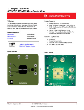
8enough viewers to support more than one or twostations. It is this economic limit which hasretarded the development of UHF televisiononce thought to be the key to diversity and localism in television service because of the numberof channels.CATV systems grew in towns whose citizensreceived either poor reception or no signals atall. These systems typically provided one to fivebroadcast TV signals to subscribers, and thus werenot radically different from broadcast televisionservice.However, cable TV systems do use coaxial cableas a medium for delivering television signals, withcharacteristics different from broadcast TV. AHence, the number of stations that can be carriedis limited by the number of cables one can affordto laynot by any fundamental restvictions asin broadcasting.Finally, since the cable protects signals it carriesfrom ocAside interference, it potentially canderiver i1 !1;;,ter quality signals than those receivedoff-thcx.A CA,TV system consists of three components:A headend, or control centerA distribution systema network of cableswhich delivEr signals to subscribers' homesA subscriber terminalin this case, merelythe subscriber's television set.single cable can carry as ,many as 40 televisionsignals that do not interfere with each other fromone point to another. Further, because signals carried by cable'Veak" only slightly from the insideof the cable, q.re frequencies used in one cableHEADENDcan be used again in another cable next to it.antenna mouir:ed on it for each broadcast televi-The headend includes an electronic controlcenter (sec. Figure 1), which may or may not behoused near e 100 to 500 foot tower with a sensitiveTable 1. TV Channel Allocations onburg, Va.and Philadelphia, Pa.345WRC-TVWTTGRichmond, Va. andPhiladelphia, Pa.67WMAL-TVRichmond, Va. andLancaster, Pa.910s WTOP-TVAltoona and Philadelphia, Pa.11 .WBAL-TV12Richmond, Va.,), Wilmington, Del. andLynchburg, Va.But separate cable systems in Baltimore and Washington could each carry a full twelve channels (2 through 13)without the possibility of major interference.Source: Charles Tate, ed., Cable Television In the Cities: ComniUnity Control, Public Access and Minority Ownership (Washington: TheUrban Institute, 1971), p. 9.
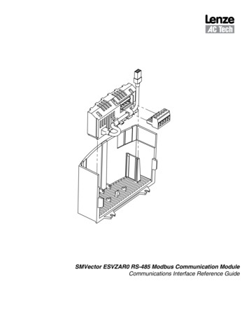
9DISTRIBUTION SYSTEMThe process of transporting signals trom theheadend to the subscriber is commonly referredto as "downstream" communication; the traditional cable system,is capable of communicationin the downstream direction only. The distributionsystem for one-way communication consists of acoaxial cable and the electronics necessary totransport signals from the headend to the subscriber. The basic element is a coaxial cable; thecable consists of an inner conductor, generally,-!aFigure 1. Control Center for a Cable Television System Headend.sion signal received by the system (see Figure 2).The antenna is sited to provide the best availablesignal reception. Each received television signalpasses through a processing amplifier, whichseparates the sound and picture components, andadjusts the signal levels to prevent a strong signalfrom one channel from overpowering another onan adjacent channel (as often happens in broadcast television): Thus, all 12 VHF channels can beused. The amplifier then reassembles the pictureand sound signals for transmission th roughout thedistribution system.UHF signals are broadcast at levels above therange of frequencies which can be transmittedmade of copper or copper-clad aluminum surrounded by an insulator (such as extruded foampolystyrene or extruded foam polyethylene)which is in turn enclosed by an outer conductor,typically aluminum (see Figure 3). Coaxial cablesused by the cable television industry range indiameter from one-quarter to one inch.plastic sheathing\1outer conductorvia cable electronics. In a cable system which alsocarries UHF television signals, the headendincludes electronic equipment to convertUHF signals to unused VHF channel frequencies withinthe cable system spectrum.plasm foiminner conductorFigure 3. Coaxial Cable.The distribution network, or "plant," is dividedinto two portions, trunk lines and feeder lines.Trunk lines, which are constructed of one-half tothree-quarter inch coaxial cable, are the majorarteries of the cable system. They transport thesignals from the headend to the extremities ofthe cable system. Feeder lines, which are connected to the trunk lines, carry signals past eachhome. In a typical distribution plant, there is twoto five times as much feeder cable as trunk cable.Although individual trunk lines are longer thanfeeder lines, there are a far greater number offeeder lines.Both the trunk line and feeder lines employ elec-tronic amplifiers which are installed at specificintervals to boost the cable signal, as shown inFigure 4. Feeder lines are connected to the trunkFigure 2. Antennas and Tower for a Cable Television SystemHeadend.lines by an electronic device called a bridgeramplifier. This amplifier draws signal power from
10cable and amplifiers introduce random electronicimpulses into the television signal as it travelsthrough the distribution system. These impulsesare called "noise," and appear on the televisionscreen as snow. Since each amplifier boosts boththe signal and the noise, there is a limit to thetotal number of amplifiers which can be attachedto a length of cable. Current design permits signalsto be processed by 18 to 25 trunk amplifiers ina row ("cascade") before the amount of snowbecomes objectionable.The distance between amplifiers depends uponthe degree to which each amplifier boosts thesignal. The amount of boost is limited becauseat high signal output, the amplifier produces otherkinds of signal degradation. These degradations,called intermodulation and cross-modulation dis-tortion, appear on the television set as movingbars or stripes.Trunk cable amplifiers are operated at lowpower levels to minimize amplifier-produceddegradation. In practice, the distance betweentrunk amplifiers is about 2,000 feel. Thus, in combination, the amplifier cascade limit and the maxFigure 4. Cable and Amplifier.the trunk for further distribution, and protects thetrunk lines from electronic disturbance in thefeeder lines.Subscribers' television sets are connected to thefeeder lines with. a subscriber "drop" line. Thesubscriber drop consists of a tap at the feeder,the drop cable (typically one-quarter inch diameter cable), and a room wall plate connector. Ashort length of coaxial cable runs from the wallplate and is connected to the antenna terminalsof the television set via a matching transformer.An understanding of the electronics in the distribution system is helpful in making decisionsabout system layout and capacity.imum distance between amplifiers defines themaximum distance for trunk cable to be 7 to 10miles.Feeder cable amplifiers (sometimes called lineextenders) feed signals to the subscriber. Theyare operated at higher power levels than trunkamplifiers in order to permit more subscribers tobe fed from a single amplifier. Since the feederamplifiers are operated at higher power levels thanthe trunk amplifiers, the number of cascadedfeeder amplifiers is normally limited by (1:stortionconsiderations to three. The distance betweenfeeder amplifiers is less than between trunkamplifiers, because the large number of subscribers drain signal from the feeder cable. In prac-Two problems in the electronic operation ofcable system distribution limit the size of the geographical area a single cable system can serve. Theyi»are termed attenuation and distortion.Coaxial cable attenuates, or weakens, a signalit carries. As a television signal, flows throughcable, the signal strength, or power of the television signal, diminishes; a typical coaxial cabletrunk line has its signal reduced to 1/100 of itsoriginal strength for approximately every 2,000III)) I4'4feet of cable. The reduction of signal strengthbecomes perceptible to the viewer as a 'snowypicture. To counteract this attenuation, amplifiersare connected to the coaxial cable to boost signalstrength.Unfortunately, the amplifiers themselvescause the second problemdistortion. BothFigure 5. Cable Distribution Network for a Cable TelevisionSystem.
lice, feeder cable extends no more than 4,000 feetfrom the trunk, and often less. Figure 5 illustratea typical trunk and feeder network.SUBSCRIBER TERMINAL"Subscriber terminal" is a term more appropriate to the description of advanced rather thanMHz-S06UHF tekvision(channels 14 to 70) contemporary systems. Here, in the case of tradi-600tional CATV systems, the term refers simply tothe subscriber's television receiver; in an advanced cable system it would consist of a television receiver in addition to other facilities, andwould he capable of two-way communication andother services.The standard television receiver is capable ofreceiving two bands of television broadcast frequencies: VHF and UHF. Unfortunately, as Figure6 illustrates, present cable electronics design frequencies are not broad enough to encompass UHFtelevision frequencies. System operators deal withthis problem partially, by converting UHF signalsat the headend to unused VHF channels. But whilethe operators can deliver as many as 35 channelsto subscribers' homes, the standard television receiver can receive no more than 12 of thosechannels.'500400Aeronautical and mobile. communications300VHF television(channels 7 to 13)Aeronautical and mobilecommunicationsbroadcast signals. These circuits are not necessaryFM radioVHF television(channels 2 to 6)all 35 channels from the cable. Research anddevelopment is taking place, but as yet there isIIIII200174The standard receiver is equipped with electronic circuits that enable it to tune and receivefor cable reception and may introduce unwantedbroadcast signals that will interfere with cable,systerns. This problem can be reduced if the cableoperator is permitted to modify the-Inside of thetelevision receiver or connect the cable directlyto the tuner.A more practical solution is the developmentof a special cable receiver, designed to receive)16Mobile communicationsApproxin ate rangeof fret uencieson cable10888100II543011011111113Figure 6. Television Frequency Spectrumsmall to support a television station, or too farfrom cities that did have stations. Traditional CATVwas essentially a retransmission service; but asthe cable industry flourished, traditional systemsno such cable receiveron the market. In the mean-provided the economic base for the furthertime, other arrangements have been devised todevelopment of cable television technology.Traditional cable television systems developedincrease capacity. These arrangements will be discussed later in more detail.B. Modern Cable TelevisionTraditional cable television was developed toprovide television service to communities too'Although cable electronics permit transmission of 40 television channels simultaneously, at present no manufacturer hasdesigned a system that delivers more than 35 channels to subscriber's': Thus, although the electronic capacity of cable is40 ch;?,nnels, subicriber service for the time being will probahlybe iunited to 35 channels.in areas where broadcast television is poor. Today,systems are built in areas where broadcast televi-sion service is available. Consequently, the provision of standard television signals will not beenough, and cable operators in urban environments will have to provide new and more diverseservices. The result will be a more technically complex cable system.1. Headends are becoming more sophisticated,with the addition of new features:Electronic importation of distant television stations
12Live studio programming exclusively for thecable systemAutomated programming of news and weatherMultiple headend interconnection for largesystems.2. Distribution systems are beginning to havemore capacityas many as 35 channels deliveredto subscribers.3. Subscriber terminals will include devices thatbypass weakne,ses of the teleion receiver.HEADENDAs in the traditional cable system, the headendin a modern system includes the antennae, andthe electronic control center for amplifying broadcast signals received and converting UHF signalsto VHF frequencies before transmitting themthrough the distribution system. Additionalmunications Commission now reouires that allsystems with more than 3,500 subscribers mustoperate to a significant extent as a local outletby origination cablecasting.'Studio facilities for cablecasting vary in cost,ranging from as low as several thousand dollarsfor facilities bUilt around a half-inch black andwhite video tape recorder, to a full color professional studio that may cost S1 million or more.Automated ProgrammingMany system headends now include automatedorigination providing specialized services otherthan conventional telecasts. Automated equipment packages provide time, weather, stock tickerand news (AP or UP) wire services, many withalphanumeric message capability. At least onemanufacturer markets a computer controlled vid-facilities are now required to produce the neweocassette player, which permits the systemoperator to play pre-recorded three fourth inchservices.videotapes automatically.Electronic Importation ofDistant Television SignalsCable systems are required to carry certain television stations which place a signal over the system's service area. Cable operators offer additional program services by importing televisionsignals from distant markets. Since the signals arereceived near the distant market and transportedto the local headend by microwave radio systems,one additional feature of a modern headend isthe equipment necessary to receive and modulatemicrowave signals.Microwave transmission is a system of broadcasting from one point to another 20 to 35 milesdistant. To import a television station, a transmitter near the station radiates the signal in a specificrathertoward the distant receiverdirectionthan uniformly in all directions as is done withradio and television broadcasting. Microwave stations must be cascaded when stations from greatdistances are imported. For example, importinga television station from a market 200 miles awaymight require "hops" between three to five microwave stations. Microwave service may be pro-vided by the telephone company, or byspecialized common carriers, or it may be ownedby the cable system operator himself.Live Studio ProgrammingSystem operators frequently operate !ocalstudios to program a channel. The Federal Com-Multiple Headend InterconnectionHeadends are now becoming increasingly com-plex because of the need for interconnection of.systems. Interconnection is necessary when ast: large that it must be served bycommunit-,several headends and distribution systems (called"hubs"): It may also develop when several contiguous cable systems in neighboring communities interconnect to share local programming.Interconnection can be achieved by cable (including a new one inch cable with low signal losscharacteristics, called "supertrunk"), or by microwave. This microwave is not the one-pointto-another kind used to import distant televisionsignals, but a new service called Local DistributionService (LDS). These microwave systems have thecapability of transporting a large number of televi-sion pictures (from 8 to 38) from one site to anumber of receiving locations, without visibledeu.Idation of signals (see Figure 7). Supertrunkis usually favored over LDS where weather conditions do not allow reliable LDS operation or wheretwo-way capability is required, such as in a systemwith a number of local origination studios thatneed to be interconnected. However, in urban'In United States v. Midwest Video Corp., 406 U.S. 649 (1972),the Supreme Court upheld the FCC's authority to impose theorigination requirement. In the course of that litigation, however, the commission stayed the effect of the rule. Upon affirmation by the Supreme Court, the commission did not moveto vacate the stay. There is some question, though, whethersuch action was necessary and the commission has not statedwhether the rule is in effect.
13environments where underground construction isnecessary, microwave may be the least expensiveone-way interconnection system. In some circumstances, a combination microwave and cable sys-tem for two-way interconnection may be lessexpensive than an all-cable system.If interconnection of cable systems is desired(either presently or in the future), the technicalstandards for the distrih,n system must bemore strict than those for.ind alone" system.Whether microwave or caith., is used to interconnect hubs, some additional distortionsbothmore noise (snow) and more in termodulation aridcross-modulation (moving bars)will occur. Asa result, to obtain the same quality signals as thosecarried by a single hub system, the number oftrunk and feeder amplifiers cascaded in a multiplehub system must be smaller.Traditional systems use a one-way "tree" layoutthat is, allthat can be likened to a party linesubscribers share the same facilities and receiveFigure 7. Microwave Interconnection of C.:ble Television Systems.the same programming (see Figure 8). A "fullyswitched" system such as the nationwide telephone network permits two-way private line com-munications by connecting each subscriberdirectly to a vast network of switching centers andalternate signal routes (see Figure 9). Intercon-nection, if properly designed, helps offset theparty line character of cable system.Interconnection permits headends to act asswitching centers. Interconnection switchingfacilities allow one hub to receive programs ofparticular interest to its subscribers, while anotherhub does not. Or, switching facilities within a hubmay also permit subscribers connected to aspecifi, trunk to receive special programming (forexample, a locally cablecast high school baseballFigure 8. Cable Television Systems Use a Tree-Shaped Network.game) while other trunks do not. Such limitedswitching capabilities are not nearly as sophisticated as the fully switched telephone system,but they do increase the flexibility of downstreamone-way service and in the future may increasethe efficiency of two-way services.Although switched cable systems exist, they areriot widespread in the United States. Switchingcenters are costly, and urban communities wouldrequire a large number of centers. Furthermore,the cost of laying the large number of cablesrequired might be prohibitive, especially if thecables were placed underground.DISTRIBUTION SYSTEMf",The modern distribution system consists of thecoaxialsame elements as the traditional onecable, amplifiers, and so on. However, with theFigure 9. Telephone Systems Use a Switched Network.
14increase in the number of services provided,several problems arise. As mentioned earkr, astandard television receiver is capable of receivingonly 12 of the35 channels cable can carry. Further,a strong local broadcast signal will interfere witha cable signal carried on the same channel whenthe two signals meet in the television receiver,making that channel unusable. Thus, distributionsystems have to be modified to overcome theselimitations.Two approaches have been developed to solvethese problems. The first, and generally the mostexpensive, is to bring additional cables to eachhome and provide a switch allowing the subscriberto switch from cable to cable, receiving up to 12channels on each one. This approach uses only12 of the 35 channels in each distribution cablebut it does provide a means of receiving morethan the 12 channels on the television set. Further,this approach led the cable industry to developprototype advanced two-way systems based onthe presumption of a dual cable distributionsystem.The second approach does not involve the dis-tribution system, but rather the subscriber terminal.SUBSCRIBER TERMINALMore recently, system operators have increasedcapacity by installing a converter instead of extracables. Depending on the model, the converterpermits the subscriber to tune any of 26 to 35cable channels. The converter translates theincoming signal selected by the subscriber to aVHF frequencythe best suited to reception bythe television set. Thus, with a converter, a subscriber may receive from 26 to 35 channels froma single cable. Greater channel capacity can beachieved by using both multiple cable and converters.The converter rests on top of the televisionreceiver and takes the place of the receiver's tuning mechanism (see Figure 10). Current versionscost about 23 to 35 each.Figure 10. A Switched Converter.C. Broadband CommunicationsCable's FutureModern cable television has evolved from aretransmission system providing basic receptionto an expanded medium for delivering one-wayservices to subscribers. With the addition ofimported signals, au tomated origination, and localprogramming, cable television has surpassed thecapabilities of broadcast television and is well onthe way to becoming the "television of abundance" envisioned by the Sloan Commission.'Cable technology promises two-way communications for subscribers, and the potential of broad-band communication networks in the future.THE EVOLUTION OFCABLE TECHNOLOGY:TWO-WAY COMMUNICATIONCable's most glamorous aspect is its "bidirectional," or two-way, capability. For the mostpart, this capability exists now only in prototype.Little is known about the future market for twoway communications; system operatoi ,, therefore, are likely to be cautious when consideringinvestment in two-way equipment.Two fundamental kinds of two-way systems areenvisioned for cable communications: institutional two-way systems for a few users, and subscriber systems for all subscribers. Institutionaltwo-way systems may involve two-way data communications or two-way video communications.Most of the electronics for these systems arealready on the market.Subscriber systems involve three prospectiv
However, cable TV systems do use coaxial cable as a medium for delivering television signals, with . Control Center for a Cable Television System Headend. sion signal received by the system (see Figure 2). The antenna is sited to provide the best available signal reception. Each received television signal