Transcription
VIRGINIA DEPARTMENT OF TRANSPORTATIONSTRUCTURE AND BRIDGE DIVISIONINSTRUCTIONAL AND INFORMATIONAL MEMORANDUMGENERAL SUBJECT:Ancillary StructuresNUMBER:IIM-S&B-90.2IIM-TE-382.1SPECIFIC SUBJECT:VDOT Guidelines to AASHTOStandard Specifications for StructuralSupports for Highway Signs,Luminaries, and Traffic Signals, 6thEdition, 2013 with 2015 interimsDIVISION ADMINISTRATOR APPROVAL:Date:/original signed by/Kendal R. Walus, P.E.State Structure and Bridge EngineerApproved: April 28, 2016April 28, 2016SUPERSEDES:IIM-S&B-90.1/original signed by/Raymond J. Khoury, P.E.State Traffic EngineerApproved: April 28, 2016Changes are shaded.The following VDOT Guidelines to the AASHTO Standard Specifications for Structural Supportsfor Highway Signs, Luminaires, and Traffic Signals, 6th Edition (LTS-6), 2013 with 2015 interims,are effective for projects as stated below.Effective Date:Future contracts: This Memorandum shall be effective for all contracts with an advertisementon or after July 1, 2016.Existing contracts: Requirements in this Memorandum may be applied under existing contracts(including existing Regional Traffic Signal Construction Contracts) if the change is approved bythe Project Engineer.Land use permit for private developments: this Memorandum shall be effective for all projectswhere the design is submitted to VDOT on or after July 1, 2016.Design-Build or PPTA projects: this Policy shall be effective for projects with RFP released onor after July 1, 2016.
Instructional & Informational MemorandumIIM-S&B-90.2Sheet 2 of 10General Requirements:Variance from the VDOT Guidelines to these specifications shall require a Design Waiver. Forcomplete information on and requirements of Design Waivers, see Section Pre.02 of Part 1 ofthe Manual of the Structure and Bridge Division.Any AASHTO Specification optional design parameter noted as “may be used at the discretionof the owner” that are not addressed in this document shall not be used for design.Square tube sign post, wood post, SSP-VA and SSP-VIA structures shall be provided inaccordance with the requirements as shown in the VDOT Road and Bridge Standards.Lighting (conventional and high mast), signal (overhead, mast arm and span wire), pedestalpoles, overhead (span, cantilever and butterfly) sign structures and ITS structures (camera poles,dynamic message signs (DMS), etc.) shall conform to the requirements of the AASHTO StandardSpecifications for Structural Supports for Highway Signs, Luminaires, and Traffic Signals, 6thEdition (LTS-6), 2013 with 2015 interims with the following clarifications:SECTION 2: GENERAL FEATURES OF DESIGN:For additional requirements related to general features of design, see VDOT Road and BridgeSpecifications, Section 700 and VDOT Road and Bridge Standards, Section 1300. Seecurrent IIM-S&B-89 for maximum span limits on ancillary structures and moratorium on bridgemounted sign structures.SECTION 3: LOADS:Wind Loading: (LTS-6 Article 3.8 and Appendix C) The alternate method for wind pressuresprovided in AASHTO Appendix C shall be used. Linear interpolation between wind contours isnot permitted. The next higher contour shall be used for design. Reduced forces shall not beused for free swinging traffic signal and free swinging sign wind loadings. See Appendix A forwind maps of Virginia.For special wind regions in Bristol District shown on maps in Appendix A, the selection of thedesign wind speed shall consider localized effects. The minimum design wind speed for 50 yearmean in these areas is 90 MPH, 25 year mean in these areas is 80 MPH and 10 year mean inthese areas is 70 MPH.For bridge mounted structures/light poles and other site condition where structures may beelevated above the surrounding terrain, the height factor used shall be increased to account forthe increased wind effects.(LTS-6 Article C.2) Wind speeds using 50-year mean recurrence shall be used for allconventional light poles, high mast light poles, ITS device support poles and overhead signstructures (span, cantilever and butterfly). Wind speeds using the 10-year mean recurrenceshall be used for SSP-VA, SSP-VIA, square tube post and other ground mounted structures.
Instructional & Informational MemorandumIIM-S&B-90.2Sheet 3 of 10SECTION 3: LOADS: (cont’d)(LTS-6 Article C.2) Mast arm signal poles, mast arms, and strain poles shall be designed usingthe following wind speeds:VDOT TrafficOperations RegionSouthwestNorthwestNorthernCentralEasternVDOT Districts WithinThat RegionBristol, Salem, andLynchburgStaunton and CulpeperNorthern VirginiaRichmond andFredericksburgHampton RoadsDesign Wind Speedfor strain poles, mastarms, and mast armpoles70 MPH70 MPH80 MPH80 MPH90 MPHMast arm signal pole and strain pole foundations shall be designed for wind speeds at thefoundation location using the 25-year mean recurrence.SECTION 5: STEEL DESIGN:Laminated Structures: (LTS-6 Article C5.1) Laminated or multi-ply structures shall only beused in tapered sections.Holes and Cutouts (Unreinforced and Reinforced): (LTS-6 Article 5.14.5) The location andsize of hand holes and cutouts shall be in accordance with the details as shown in the VDOTRoad and Bridge Standards. For high mast light poles, the width of unreinforced and reinforcedholes and cutouts in the cross-sectional plane of the tube shall not be greater than 50 percentof the tube diameter at that section.Welding: A connection detail using a full penetration groove weld with a backing ring may beconsidered for signal mast arms and high mast light poles. The backing ring shall be attachedat the top and bottom face of the ring using a continuous fillet weld.
Instructional & Informational MemorandumIIM-S&B-90.2Sheet 4 of 10SECTION 11: FATIGUE DESIGN:Fatigue Importance Categories: (LTS-6 Article 11.6)The following fatigue importance categories shall apply to structures:Structure TypeAll structures supportingdynamic message signsFatigue Importance CategoriesSpan Length*, ft.Overhead sign span structureOverhead sign cantileverstructureOverhead sign butterflystructureAll span lengthsCategory I 150 150 50 50Category ICategory IICategory ICategory IIAll span lengthsCategory II 7550 to 75 50 190Overhead signal structure 190High mast light polesAll lengthsSignal span wires, conventional lights poles and ITS devicesupport poles (excluding DMS)Signal mast arm structure**Fatigue CategoryCategory ICategory IINo fatigue design requiredCategory ICategory IICategory INo fatigue design required* Span length is defined as center-to-center of column(s) for span structure and face-of-columnto tip of arm for cantilever and signal structures.** For twin mast arms, The pole, arms and connections shall be designed for the applicable fatiguecategory for the longest arm attached.Mitigation Devices: (LTS-6 Article 11.6 and 11.7.1) Mitigation devices shall not be used in lieuof designing for fatigue.Aluminum Light Poles: (LTS-6 Article 11.6 and 11.7.1): Internal first and second modevibration dampeners shall be provided and installed according to the manufacturer’sinstructions in all cases. External dampeners may be used if approved by the Engineer.Galloping Loads: (LTS-6 Article 11.7.1) Galloping loads shall not be considered in the designof overhead sign cantilevered structures with four chord trusses, signal mast arm structures,and multi-chord overhead signal structures.Truck-Induced Gust Loads: (LTS-6 Article 11.7.1.3) Truck induced gust loads shall not beconsidered in the design of signal mast arm and overhead signal structures.Vertical Deflection: (LTS-6 Article 11.8) The vertical deflection of the free end of the arm foroverhead sign cantilevered structures due to the wind load effects of galloping or truck-inducedgusts shall not exceed 8”.
Instructional & Informational MemorandumIIM-S&B-90.2Sheet 5 of 10Section 13: FOUNDATION DESIGN:(This section provides guidance/modifications on the AASHTO Standard Specifications forHighway Bridges, 1996; 1997 and 1998 Interim Specifications as referenced in the AASHTOStandard Specifications for Structural Supports for Highway Signs, Luminaires, and TrafficSignals.)Geotechnical Design: The factor of safety shall be as follows:MINIMUM FACTORS OF SAFETYDrilled ShaftOverhead SignStructures and allother types ofMast arm trafficancillary structuresSignalsexcept for Mastarm traffic g/SkinFrictionOverturning(Broms Method)Spread he factors of safety shown above already account for the 1.33/1.40 group overload/overstress factor. No reduction shall beapplied to the design loading used in the analysis.))(1) Torsion(2)Resistance shall be evaluated as specified by the AASHTO LRFD BRIDGE DESIGN SPECIFICATIONS(Version adopted by current IIM-S&B-80) Section 10.8.3.5- Nominal Axial Compression Resistance of Single DrilledShafts. A value of 1.0 shall be used in lieu of the resistance factors as shown in Table 10.5.5.2.4-1.Passive resistance shall be reduced by 50% to limit foundation movement.Geotechnical Design: In capacity calculations for the foundation design of a drilled shaft, thesoil resistance of the top 1.5 feet shall be neglected in the analysis for torsion/skin friction/tipresistance. The full length of the shaft from the ground surface to the tip may be used inoverturning/horizontal deflection. The remainder of the shaft may be assumed to be fullyeffective in supporting applied loads.Horizontal Deflection: In lieu of Broms method, COM624P or other commercially availablesoftware may be used to evaluate the overturning of shafts and to estimate shaft deflections.For mast arm signals and span wire signals, the total horizontal deflection shall be limited to0.75 inches at the ground level and the tip of the pile deflection shall not exceed -0.25 inches.For other structures, the total horizontal deflection shall be limited to 0.50 inches at the groundlevel and the tip of the pile deflection shall not exceed -0.15 inches. The loading used in theanalysis shall not be reduced by the allowable overload/overstress factor. The shafts shall bemodeled such that the nonlinear flexural rigidity (non-linear EI, or “cracked” section) isaccounted for when the horizontal deflections are calculated.
Instructional & Informational MemorandumIIM-S&B-90.2Sheet 6 of 10Section 13: FOUNDATION DESIGN:(Cont’d)Reinforcement: Where tremie placement of concrete is anticipated, a minimum spacing of 5inches or 10 times the size of the largest coarse aggregate whichever is greater shall beprovided in both horizontal and vertical direction. For dry shafts, a smaller space of 5 times thesize of the largest coarse aggregate may be considered. A dry shaft is when the amount ofstanding water in the base of the shaft prior to concreting is less than or equal to 3 inches andwater is entering the shaft at a rate of less than 12 inches/hour.CC:Chief EngineerDeputy Chief EngineerState Operations EngineerState Location and Design EngineerState Operations EngineerAssistant State Structure and Bridge EngineersAssistant State Traffic Engineer – Traffic Control DevicesDistrict Structure and Bridge EngineersState Traffic Design Program ManagerRegional Operations DirectorsDistrict Transportation & Land Use DirectorsRegional Operations Maintenance ManagersRegional Traffic EngineersFHWA Virginia AdministratorFHWA – Bridge Section
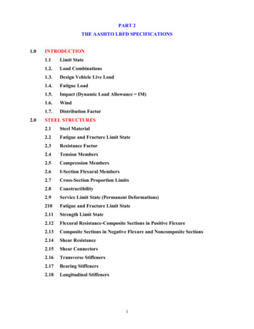
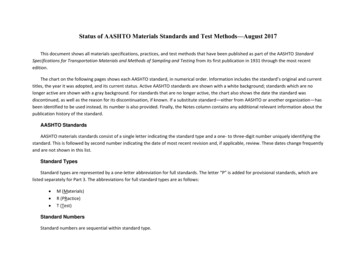
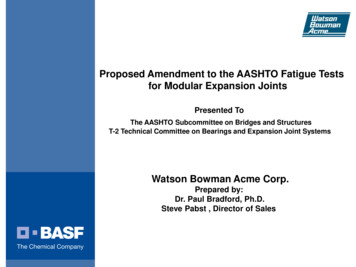
Instructional & Informational MemorandumIIM-S&B-90.2Sheet 7 of 10Appendix A(Wind maps developed based on charts from Appendix C AASHTO Standard Specifications forStructural Supports for Highway Signs, Luminaires, and Traffic Signals, 6th Edition, 2013)
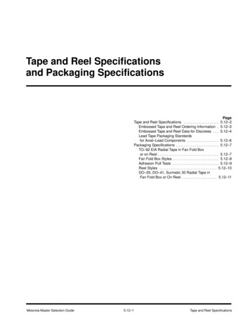
706070606070708080Instructional & Informational MemorandumIIM-S&B-90.2Sheet 8 of 10Figure A.3-1—Isotach 0.10 Quantiles in mph: Annual Extreme-Mile 9.1 m (30 ft) AboveGround, 10-yr Mean Recurrence Interval; VirginiaSpecial Wind Region
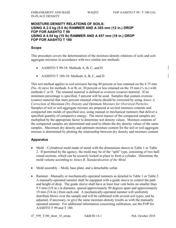
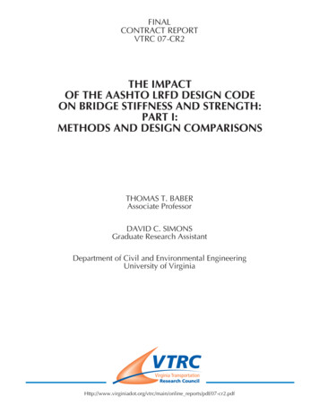
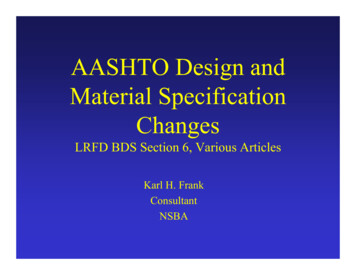
7080707080809090Instructional & Informational MemorandumIIM-S&B-90.2Sheet 9 of 10Figure A.3-2—Isotach 0.04 Quantiles in mph: Annual Extreme-Mile 9.1 m (30 ft) AboveGround, 25-yr Mean Recurrence Interval; VirginiaSpecial Wind Region
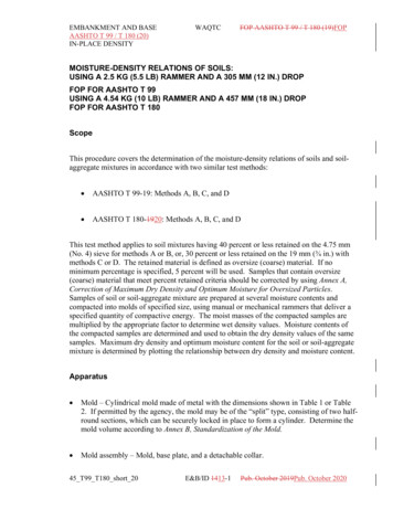
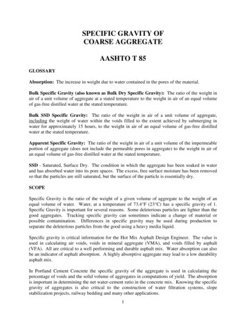
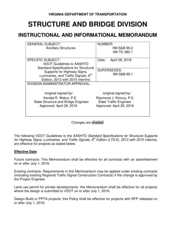
1007090707080809090100Instructional & Informational MemorandumIIM-S&B-90.2Sheet 10 of 10Figure A.3-3—Isotach 0.02 Quantiles in mph: Annual Extreme-Mile 9.1 m (30 ft) AboveGround, 50-yr Mean Recurrence Interval; VirginiaSpecial Wind Region
The following VDOT Guidelines to the AASHTO Standard Specifications for Structural Supports for Highway Signs, Luminaires, and Traffic Signals, 6th Edition (LTS-6), 2013 with 2015 interims, are effective for projects as stated below. Effective Date: Future contracts: This Memorandum shall be effective for all contracts with an advertisement on or after July 1, 2016. Existing contracts .