Transcription
Intuitive Guide to Principles of CommunicationsBy Charan Langtonwww.complextoreal.comCoding Concepts and Block CodingIt’s hard to work in a noisy room as it makes it harder to think. Work done in such environment is likelyto cause more mistakes. Electronic devices suffer much the same fate. Signals too are apt to be misinterpretedin an environment that is “noisy”.During a conversation how do you determine if you heard the other person correctly? We human receiversemploy various forms of error detection and correction as we try to make sense of what we are hearing. First ofall, we use context and if a word or phrase does not seem to fit the topic of conversation, we automaticallyreplace the confusing section with what we expect to hear. If contextual confusion still exists, we ask the personto repeat what he has just said or we may ask the other person to speak louder. All of these are forms of errorcorrection schemes employed during human communication.Error detection and correction (EDC) to achieve good communication is also employed in electronicdevices and in much the same conceptual way. In fact, without EDC most electronic communication would notbe possible. The level of noise and interferences are just way too high in electronic medium. The amount ofEDC required and its effectiveness depends on the signal to noise ratio, or SNR.EDC can be implemented in the five following ways.Increase signal powerThis is same as speaking louder in a noisy room. We intuitively know that as the signal to noise ratio isincreased, the errors decrease. Assuming that we can do nothing about the environment, the most obvious thingto do is to increase the transmitter power. But this is not always possible. Most communication devices have noability to increase power. Examples of power-limited devices are telephone handsets and satellites. Both ofthese have a fixed amount of power and can not increase their transmitting power beyond a certain point. Infact most are designed to operate at their maximum power and have no spare power available.There are actually some disadvantages to using this scheme. When amplifier characteristics are not linear,increasing the power means both signal and noise are amplified making the situation worse. You can see thismechanism at work in a radio. When you increase the volume, the noisiness of the signal goes from bad tointolerableDecrease signal noiseWe are at a party and the room is too noisy for conversation, we may move to a quieter corner wherethere is less noise. If you turn on the air conditioner in the room and the TV reception goes bad, you turn off theoffending item to improve the reception. These are some means of noise reduction. In a communication device,the only noise that is under the designer’s control is thermal and inter-modulation noise of the system. Assuming that the system is designed to minimize these, we do not have any way of reducing the noise. We are at themercy of the environment and have to accept this as a given.
Introduce diversityWhen listening to a radio, you find that the signal is waxing and waning. Your instinctive response is tomove the radio to a different location. With a cordless phone, we may switch channels, or ask the caller to callus on a different line. In satellite communications, in wet and rainy areas, we often have two ground stationsseparated by some distance, both receiving the same signal so as to increase the SNR. Different polarizationswhich are used to expand the useable spectrum in satellite communications can also be used to send the sameinformation as a means of error correction. All of these techniques fall under the category of diversity, the mainpurpose of these is to improve signal quality by taking advantage of redundancy. Another from of diversitycomes to use from an unexpected source in the case of cell phones. The bouncing around of the signals causesamplitude reduction but with sophisticated signal processing we can actually use these low-power interferingsignals to combine and improve the SNR.RetransmissionRepeat retransmission is a special form of diversity. With the addition of a return acknowledgement thatthe signal was received correctly makes it a scheme called Acknowledgement Retransmit or ARQ. ARQtechniques require a duplex transmission. Each block is checked by the receiver, and in case of errors, retransmission is requested. If the SNR is high, there is very little retransmission and the throughput is high. If SNRdips, then overhead increases greatly. Here the tradeoff is between the overall bandwidth, and delay on one sideand the receiver complexity (which is reduced greatly) on the other side. ARQ is used most commonly in wiredand local area networks. Downloading files over the internet is one place where these techniques are used. Youcan monitor this occurring when waiting for a page to download on the web. The out-going blocks are the ARQblocks. In most cases, we can see that the overhead is quite high (usually about 15%).Forward Error CorrectionWhen a duplex line is not available or is not practical, a form of error correction called Forward ErrorCoding (FEC) is used. The receiver has no real-time contact with the transmitter and can not verify if a blockwas received correctly. It must make a decision about the received data and do whatever it can to either fix it ordeclare an alarm.FEC techniques add a heavy burden on the link either in adding redundant data and adding delay. Alsomost FEC techniques are not very responsive to the actual environment and the overhead is there whetherneeded or not. Another big disadvantage is the lower information rate. However at the same time, these techniques reduce the need to vary power. For the same power, we can now achieve a lower error rate. The communication in this case remains simplex and all the burden of detecting and correcting errors falls on the receiver.The transmitter complexity is avoided but is now placed on the receiver instead.Digital signals use FEC in these three well known methods:1. Block Codes2. Convolutional Codes3. InterleavingBlock codes operate on a block of bits. Using a preset algorithm, we take a group of bits and add a codedpart to make a larger block. This block is checked at the receiver. The receiver then makes a decision about thevalidity of the received sequence.Convolutional codes are referred to as continuous codes as they operate on a certain number of bitscontinuously.Interleaving has mitigating properties for fading channels and works well in conjunction with these twotypes of coding. In fact all three techniques are used together in many EDC suites such as Digital Video
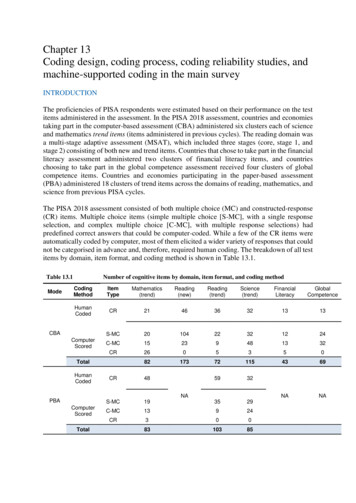
Broadcast, satellite communications, radio and cell phones and baseband systems such as PCs and CD players.In this Tutorial we will cover the workings of block codes in detail.Block Codes.Block codes are referred to as (n, k) codes. A block of k information bits are coded to become a block of nbits.But before we go any further with the details, let’s look at an important concept in coding called Hamming distance.Let’s say that we want to code the 10 integers, 0 to 9 by a digital sequence. Sixteen unique sequences canbe obtained from four bit words. We assign the first ten of these, one to each integer. Each integer is nowidentified by its own unique sequence of bits as in Table below. The remaining six possible sequences areunassigned.Table I – Assigning 4-bit sequences to the 10 teger Sequence00001 120011 340101 560111 781001 UnassignedUnassignedUnassignedThe universe of all possible sequences is called the code space. For 4-bit sequences, the code spaceconsists of 16 sequences. Of these we have used only ten. These are the valid words. The ones not used orunassigned are invalid code words. They would never be sent, so if one of these is received then the receiverassumes that an error has occurred.Figure 1 – Codeword space is a list of all words possible form a particular alphabet size such as 4-bit
words shown. The valid codewords are a subset of these codewords that are mapped with actual data such asthe 10 codewords that are each assigned to one of the 10 digits.Hamming Weight: The Hamming weight of this code scheme is the largest number of 1’s in a validcodeword. This number is 3 among the 10 codewords we have chosen. (the ones in the while space)Concept of Hamming DistanceIn continuous variables, we measure distance by Euclidean concepts such as lengths, angles and vectors.In the binary world, distances are measured between two binary words by something called the Hammingdistance. The Hamming distance is the number of disagreements between two binary sequences of the samesize. It is a measure of how apart binary objects are.The Hamming distance between sequences 001 and 101 is 1The Hamming distance between sequences 0011001 and 1010100 is 4Hamming distance and weight are very important and useful concepts in coding. The knowledge ofHamming distance is used to determine the capability of a code to detect and correct errors.Although the Hamming weight of our chosen code set is 3, the minimum Hamming distance is 1. Thecodeword 1011 and codeword 1010 differ by only one bit. A single bit error can turn 1011 into 1010. Thereceiver interpreting the received sequence of 1010 will see it as a valid codeword will never know that actuallythe sent sequence was 1011. So it only takes one bit error to turn one valid codeword into another validcodeword such that no error is apparent. Number 2 can then turn into Number 8 with one bit error in the firstbit.Now extend the chosen code set by one parity bit. Here is what we do, if the number of 1’s is even thenwe extend the sequence by appending a 1, and if the number of 1’s is odd, then we add a zero at the end of thesequence. The codespace now doubles. It goes from 16 possible codewords to 32 codewords since codespace isequal to 2N, where N is the length of the sequence. We can extend the sequence yet again using the sameprocess and now the code space increases to 64. In the first case the number of valid codewords is 10 out of 32and in the second case it is still 10 but out of 64, as shown in Column 4.Table II – Codespace vs. valid codewords, extending the sequence by adding a parity bitInteger4 bit Seq.Extended by 1 bitExtended again by 1 bit0 0000 00000 0000001 0001 00011 0001102 0010 00101 0010103 0011 00110 0011004 0100 01001 0100105 0101 01010 0101006 0110 01100 0110007 0111 01111 0111108 1001 10010 1001009 1010 10100 1010006 more not used 22 more not used52 more not usedWe now have three code choices, with 4, 5 or 6-bit words. The Hamming weight of the first set is 3, 4 for
the second set and 5 for the last set. The minimum Hamming distance for the first set is 1. The minimumHamming distance for the second set is 2 bits and 3 for the last set.In the first set, even a single bit error cannot be tolerated (because it cannot be detected). In the secondset, a single error can be detected because a single bit error does not turn one code word into another one. So itserror detection ability is 1. For the last set, we can detect up to 2 errors. So its error detection capability is 2bits.We can generalize this to say that the maximum number of error bits that can be detected ist dmin –1Where dmin is Hamming distance of the codewords. For a code with dmin 3, we can both detect 1 and 2bit errors.So we want to have a code set with as large a Hamming distance as possible since this directly effects ourability to detect errors. It also says that in order to have a large Hamming distance, we need to make ourcodewords larger. This adds overhead, reduces information bit rate for a given bandwidth and proves the adagethat you cannot get something for nothing even in signal processing.Number of errors we can correctDetecting is one thing but correcting is another. For a sequence of 6 bits, there are 6 different ways to geta 1 bit error and there are 15 different ways we can get 2-bit errors.6!No. of 2-bit combinations 2! 4! 15What is the most likely error event given that this is a Gaussian channel? Most likely event is a 1 bit errorthen 2 bit errors and so on. There is also a possibility that 3 errors can occur, but for a code of 6 bits, themaximum we can detect is two bits. This is an acceptable risk since 3 bit errors are highly unlikely because ifthe transition probability p is small ( 1), the probability of getting three errors is cube of the channel errorrate,PE(N) pNOf course it is indeed possible to get as many as 6 errors in a 6 bit sequence but since we have no way ofdetecting this scenario, we get what is called a decoding failure. This is also termed the probability of undetected errors and is the limitation on what can be corrected.The number of errors that we can correct is given byt (int) d min 12For a code with dmin 3, the correction capability is just 1 bit.Creating block codes
The block codes are specified by (n.k). The code takes k information bits and computes (n-k) parity bitsfrom the code generator matrix. Most block codes are systematic in that the information bits remain unchangedwith parity bits attached either to the front or to the back of the information sequence.Hamming code, a simple linear block codeHamming codes are most widely used linear block codes. A Hamming code is generally specified as (2n1, 2 -n-1). The size of the block is equal to 2n-1. The number of information bits in the block is equal to 2n-n-1and the number of overhead bits is equal to n. All Hamming codes are able to detect three errors and correctone. Common sizes of Hamming codes are (7, 4), (15,11) and (31, 26). All of these have the same Hammingdistance.nLets take a look the 7,4 Hamming code. In this code, the length of the information sequence is 4 bits. Sothere are only 16 possible sequences. The table below lists all 16 of these sequences.Table III- 16 possible sequences from a 4 bit wordSeq No.1 02 03 04 05 06 07 08 09 110111 10i21010101010101010i3We would like to add three parity bits to the above information sequences Eight different combinations of3 bits are possible. We ignore the all-zero combination and write down the remaining seven combinations inTable IV.Table IV – Creating a parity matrixSequence1 0012 0103 0114 1005 1016 1107 111
Make a note of rows 1, 2 and 4. All other rows are linear combinations of these three basis vectors. Thisproperty comes in handy when you are proving why the process I have outlined here works. But we are notgoing to dwell too much on the theory here, just the practical aspect of what this simple construct can do for us.Let’s call these seven rows matrix H. It is called the parity matrix of the code. It has n rows and n-kcolumns. For a code of (7, 4), it has 7 rows and 3 columns. We can reorder the rows of this matrix any whichway we want. The only thing to keep in mind is that we want the basis rows to be together either on top or atthe bottom. Each reordering will give us a new Hamming code. Following are just two ways we can order therows of H, each of these will result in a different code. 1 0 1 H 0 1 0 0 11010101 1 1 1 1 1 0 1 1 0 1 1 H 0 1 1 1 0 0 1 0 A different ordering of 0 0 1 0 1 0 0 1 Now we take the upper part of this matrix (under the line) and create a new matrix called G 1 0G 0 0010000100001101111011 1 1 0 Take the upper part of the H matrix (the one on the left) and add a unit matrix to the right of it, making anew matrix of size (4 x 7). This is our generator matrix, the one that tells us how the 16 info sequences will bemapped to the 16 valid codewords.Rearrangement of the rows of H will lead to a different G matrix and hence will change the mapping. Theessential point to this is that two block codes of the same size may create an entirely different mapping depending on how the rows are ordered, but each mapping has the same Hamming weight and has the same errorcorrection/detection capability.Now all we have to do is multiply the information vector d with matrix G to get a codeword c.c d.GFor information sequence [ 0, 1, 1, 0 ], we get the following transmitted codeword of length 7.
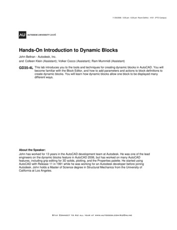
1 0c [0 1 1 0] 0 0010000100001101111011 1 1 [0 1 1 0 1 1 0] 0 Coder architectureThe coder utilizes a Linear Feedback Shift Register circuit (LSFR). Using the LSFR, The figure belowshows how the H matrix is produced using only shifts and XOR. We can produce the H matrix containing allseven rows. First five of these are shown in the figure.10010XOR(1 0)XOR(0 0)XOR(0 1)XOR(1 0)0010110101Fig 2 – Using an LSFR to create the H matrixThe following encoder architecture, proposed by Benjamin Arazi in Ref. 1 (a great book), and based onthe above LSFR produces the codeword with ingenuity and little fuss. Taking the LSFR in the Figure 2 whichproduces the rows of H matrix, we feed it an information vector, a b c d. Sequential shift of these bits throughthis LSFR give us the following contents in the three shift registers.
Contents of Registers R1, R2 and R3dc b da d c dd cb d ca d c b d0dd cb d cFig 3 – The encoder architecture using an LSFRThe last row gives the three parity bits that are then attached as tail bits to the information sequence tocreate the valid codeword.We can also then say that the equation for the parity bits isP1 a d cP2 a d c b dP3 b d cFor sequence of 0 1 1 0 , we getP1 0 0 1 1P2 0 0 1 1 0 0P3 1 0 1 0The codeword is 1 0 0 0 1 1. This codeword is different from the one calculated above because here thestarting point of the registers was different.DecodingThe main concept in decoding is to determine which of the 2k valid codewords was transmitted given thatone of the 2n has been received. We will continue with our example of the (7, 4) block code.Decoding of block codes is pretty easy. We compute something called a Syndrome of an incomingcodeword. We do that by multiplying the incoming vector by the transposed parity matrix H. (Remember wemultiply with matrix G on the encoder side and by H on the decoder side.)s HT . cThe size of the syndrome will be equal to (n-k) bit. For our example of the (7, 4) code, it will be three bitslong. Without proving, let me state that, an all-zero syndrome means no error has occurred. So we want thesyndrome to be zero.Let’s multiply the received code vector [ 0 1 1 0 1 1 0] with the HT matrix, to see if we get all zeros sincewe know that this is a valid codeword.
1 0 1 1 1 0 0 s 1 1 0 1 0 1 0 [0 1 1 0 1 1 0] 1 1 1 0 0 0 1 s [000]The results is indeed [0 0 0], an all zero syndrome.Let’s see what syndrome we get when an error is made. The received vector is now [ 1 1 1 0 1 1 0 ],the left most bit is received inverted. Now we compute the syndrome again and get 1 0 1 1 1 0 0 s 1 1 0 1 0 1 0 [1 1 1 0 1 1 0] 1 1 1 0 0 0 1 s 111Now compute the ordinal number from this sequence, we get 7. This tells us that the 7th bit is in error.Knowing this, the decoder corrects the 7th bit, which is the left most bit, from 1 back to 0)A syndrome table can be pre-created in the decoder so that a quick mapping to the bit location where theerror has occurred can be made. This is done by changing a valid code vector one bit at a time and looking atthe computed syndrome. We get the following syndrome table for this code.Table V – Syndrome to error location mappingError patternSyndrome0 0 0 0 0 0 01 0 0 0 0 0 00 0 01 1 01010110001Here is an another example, here bit no. 4 as been received in error.
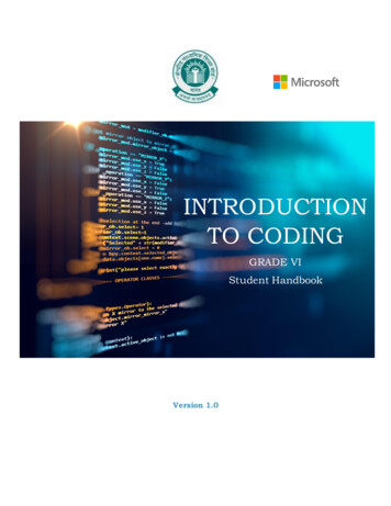
1 0 1 1 1 0 0 s 1 1 0 1 0 1 0 [0 1 1 1 1 1 0] 1 1 1 0 0 0 1 s 110We see from Table V that bit number 4 has been received in error. The syndrome tells us not only that anerror has occurred, but which bit (its location) has been received in error so it can be corrected. All single bitscan be detected and corrected in this manner. Since the probability of a single error is much larger than t 1error, this method of decoding is called the Maximum Likelihood Decoding. MLD is the most efficient methodeven though other method such as nearest neighbor would lead to somewhat better results at the expense ofdecoding speed and memory.When two errors occur, as in the case of the vector below, we get a non-zero syndrome. For non-zerosyndrome, we correct the error based on the syndrome table but this lets an error pass through unbeknownst.csent 0110110c sentrcvd 0110000Bits no. 2 and 3 are received inverted.The syndrome for this vector is 1 0 1 1 1 0 0 s 1 1 0 1 0 1 0 [0 1 1 1 0 01 0] 1 1 1 0 0 0 1 s 110This causes us to change this vector tod 0111000which is obviously wrong.What happens when we have 3 error or 4. Up to 3 erros, the syndrome will be non-zero but any numberof errors larger than 3 may give a 0 syndrome so that the errored block goes through undetected.Decoding structureThe following circuit automatically corrects one bit errors. It utilizes the LSFR circuits of Fig 2 and 3with addition of an AND gate. As the message is shifted in, the rows of H matrix are produced by R2 register.After n shifts, the register again goes back to 000. As long as the AND gate does not produce a 1, the incomingmessage is shifted out as is, with no correction. It is left to as an exercise for the proverbial student to work outthe details.
Fig 4 – Decoder that automatically corrects of one bit errorsReferences1: A Common sense approach to the theory of error correcting codesby Benjamin Arazi, MIT press, 19882. Digital Communications, I. A. Glover and P M Grant, Prentice HallCopyright 2001 Charan Langton, All Rights Reservedmntcastle@earthlink.netOther tutorials at:www.complextoreal.com
Coding (FEC) is used. The receiver has no real-time contact with the transmitter and can not verify if a block was received correctly. It must make a decision about the received data and do whatever it can to either fix it or declare an alarm. FEC techniques add a heavy burden on the link either in adding redundant data and adding delay. Also