Transcription
RoomAir ConditionersOwner’s Manual andInstallation InstructionsSafety Instructions . . . . . . . . . 2, 3Cool Only:About the Controls . . . . . . . . . . 4-9Cool Models . . . . . . . . . . . . . . . . . . . . . 4, 5Heat Models . . . . . . . . . . . . . . . . . . . . . 6, 7Vent Control. . . . . . . . . . . . . . . . . . . . . . . . 8AJCMAJCMAJCQAJCQAJCQ08, 1010, 120608, 10, 1209, 10, 9, 10, 12DCFLCFACFDCFCare and CleaningGrille and Case . . . . . . . . . . . . . . . . . . . 10Outdoor Coils . . . . . . . . . . . . . . . . . . . . 10Front Grille . . . . . . . . . . . . . . . . . . . . . . . . 10Air Filter . . . . . . . . . . . . . . . . . . . . . . . 10-11Long Term Storage . . . . . . . . . . . . . . 12Installation InstructionsBefore You Begin. . . . . . . . . . . . . . .12-13Installing a J-Model inan Existing Wall Case . . . . . . . . . . . . . 14Through-the-WallInstallation . . . . . . . . . . . . . . . . . . . . . . . 15EspañolFor a Spanish version of this manual, visitour Website at GEAppliances.com.Troubleshooting Tips . . . . . . . 16Para consultar una version en español deeste manual de instrucciones, visite nuestrositio de internet GEAppliances.com.Consumer SupportFrançaiseNormal Operating Sounds . . . . . . . 16Warranty. . . . . . . . . . . . . . . . . . . . . . . . . 19Consumer Support . . . . . . Back CoverFor a French version of this manual, visitour Website at GEAppliances.com.Pour une version française de ce manueld’utilisation, veuillez visiter notre site webà l’adresse GEAppliances.com.Write the model and serialnumbers here:Model #Serial #Find these numbers on a label on the front ofthe base pan behind the front grille.49-775402-16 GE
IMPORTANT SAFETY INFORMATION.READ ALL INSTRUCTIONS BEFORE USING.SAFETY INFORMATIONThis is the safety alert symbol. This symbol alerts you to potential hazards that can kill or hurt you and others. All safetymessages will follow the safety alert symbol and the word “DANGER”, “WARNING”, or “CAUTION”. These words are defined as:DANGERIndicates a hazardous situation which, if not avoided, will result in death or serious injury.WARNING Indicates a hazardous situation which, if not avoided, could result in death or serious injury.CAUTIONIndicates a hazardous situation which, if not avoided, could result in minor or moderate injury.WARNINGFor your safety, the information in this manual must be followed to minimize the risk of fire or explosion, electric shock,or to prevent property damage, personal injury, or loss of life.SAFETY PRECAUTIONS Turn OFF and unplug your air conditioner beforemaking any repairs or cleaning.WARNINGRisk of electric shock. Can cause injury or death. For yoursafety, the information in this manual must be followed tominimize the risk of fire, electric shock or personal injury. Use this appliance only for its intended purpose asdescribed in this Owner’s Manual. This air conditioner must be properly installed inaccordance with the Installation Instructions before itis used. Never unplug your air conditioner by pulling on thepower cord. Always grip plug firmly and pull straightout from the receptacle.NOTE: We strongly recommend that any servicing beperformed by a qualified individual. For your safety do not store or use combustiblematerials, gasoline or other flammable vapors orliquids in the vicinity of this or any other appliance. All air conditioners contain refrigerants, which underfederal law must be removed prior to productdisposal. If you are getting rid of an old productwith refrigerants, check with the company handlingdisposal about what to do. Replace immediately all electric service cords thathave become frayed or otherwise damaged. Adamaged power supply cord must be replacedwith a new power supply cord obtained from themanufacturer and not repaired. Do not use a cordthat shows cracks or abrasion damage along itslength or at either the plug or connector end.SAVE THESE INSTRUCTIONS2
IMPORTANT SAFETY INFORMATION.READ ALL INSTRUCTIONS BEFORE USING.WARNINGHOW TO CONNECT ELECTRICITYWARNINGRisk of electric shock. Cancause injury or death. This appliance must be properlygrounded. Do not, under any circumstances, cut or removethe third (ground) prong from the power cord. For personalsafety, this appliance must be properly grounded. The power cord of this appliance is equipped witha 3-prong (grounding) plug which mates with astandard 3-prong (grounding) wall outlet to minimizethe possibility of electric shock hazard from thisappliance. Have the wall outlet and circuit checked by aqualified electrician to make sure the outlet isproperly grounded. Power cord may include a current interrupterdevice. A test and reset button is provided on theplug case. The device should be tested on a periodicbasis by first pressing the TEST button and then theRESET button. If the TEST button does not trip or if theRESET button will not stay engaged, discontinue useof the air conditioner and contact a qualified servicetechnician. Where a 2-prong wall outlet is encountered, it isyour personal responsibility and obligation to haveit replaced with a properly grounded 3-prong walloutlet.WARNINGRisk of electric shock. Can cause injury or death. The air conditioner should always be plugged into itsown individual electrical outlet which has a voltagerating that matches the rating plate. This providesthe best performance and also prevents overloadinghouse wiring circuits which could cause a fire hazardfrom overheated wires. See the Installation Instructions, ElectricalRequirements section for specific electricalconnection requirements.USE OF EXTENSION CORDSWARNINGserious injury or death.RISK OF FIRE. Could cause DO NOT use an extension cord with this Built-in AirConditioner. DO NOT use surge protectors or multi-outlet adaptorswith this Built-in Air Conditioner.USE OF ADAPTER PLUGSWARNINGRisk of electric shock. Can cause injury or death. We strongly recommend against the use of anadapter plug. If you must use an adapter, where local codes permit,a temporary connection may be made to a properlygrounded 2-prong wall outlet by use of a UL-listedadapter available at most local hardware stores. The larger slot in the adapter must be aligned withthe larger slot in the wall outlet to provide properpolarity in the connection of the power cord. When disconnecting the power cord from theadapter, always hold the adapter in place with onehand while pulling the power cord plug with the otherhand. If this is not done, the adapter ground terminalis very likely to break with repeated use. If the adapter ground terminal breaks, DO NOT USEthe air conditioner until a proper ground has beenestablished. Attaching the adapter ground terminal to a walloutlet cover screw does not ground the applianceunless the cover screw is metal, not insulated, andthe wall outlet is grounded through the house wiring.You should have the circuit checked by a qualifiedelectrician to make sure the outlet is properlygrounded.READ AND FOLLOW THIS SAFETY INFORMATION CAREFULLY.SAVE THESE INSTRUCTIONS3
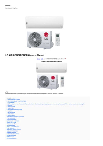
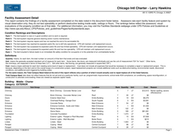
ERXW WKH FRQWUROV RQ WKH DLU FRQGLWLRQHU³&RRO 2QO\ 0RGHOVAppearance may vary.PowerCoolFanDelay DelayHrsPowerOn/OffHighMedLowOffRemote ControlAir Conditioner ControlsControlsFanCoolLights beside the touch pads on the air conditionercontrol panel indicate the selected settings.1. Power On/OffTurns air conditioner on and off.2. DisplayDisplays the temperature setting. Displays hours whensetting the timer.3. ModeOn the remote control, use to set the air conditioner toCool or Fan mode.On the air conditioner controls, use to set Cool or Fanmode at High, Med or Low fan speed. Indicator lights onthe air conditioner controls will show the mode and fanspeed selected.4. Temp Increase /Decrease – PadsUse to set temperature when in COOL mode.5. Fan SpeedsUse to set the fan speed at Low, Med or High.To cancel the Delay Timer, press the On pad until “CL”appears. Then wait until the display turns off.2II³When the air conditioner is on, it can be set toautomatically turn off in half an hour to 24 hours. Eachtouch will set the time in half hours up to 10 and then inhours up to 24.To cancel the Delay Timer, press the Off pad until “CL”appears and wait for the set temperature to be displayed.The unit will now resume normal operation.7. Reset FilterLED will turn on when fan has accumulated 250 hours ofrun time as a reminder to clean filter. Press Reset Filter toturn off the LED and reset the accumulated run time.8. Remote Control Signal ReceiverNOTE: When the air conditioner is turned on, it willautomatically start in the setting last used.6. Delay Hrs2Q³When the air conditioner is off, it can be set toautomatically turn on in half an hour to 24 hours at itsprevious setting. Each touch will set the time in half hoursup to 10 and then in hours up to 24.Remote Control To ensure proper operation, aim the remote control at thesignal receiver on the air conditioner. Make sure nothing is between the air conditioner and theremote control that could block the signal. The remote control signal has a range of up to 21 feet. 0DNH VXUH EDWWHULHV DUH IUHVK DQG LQVWDOOHG FRUUHFWO\³VHH the Care and Cleaning section.4
Cool ModeRemote Control1. Press Cool pad.2. Press Low, Med or High pads to set desired fan speed.3. Press the Increase / Decrease – pads to set the desiredtemperature 60 F to 85 F in 1 F increments.Control Panel1. Press the Mode pad until the Cool indicator light is lit and the Low,Med or High indicator light is lit for the desired fan speed.2. Press the Increase / Decrease – pads to set the desiredtemperature 60 F to 85 F in 1 F increments.A thermostat is used to maintain the room temperature. Thecompressor will cycle on and off to keep the room at the set level ofcomfort. Set the thermostat at a lower number and the indoor air willbecome cooler.Set the thermostat at a higher number and the indoor air will becomewarmer.NOTE: If the air conditioner is off and is then turned on while set toCool, it will take approximately 3 minutes for the compressor to startand cooling to begin.Cooling Descriptions)RU 1RUPDO &RROLQJ³Select the Cool mode and High or Med fan witha middle set temperature.)RU 0D[LPXP &RROLQJ³Select the Cool mode and HIGH fan with alower set temperature.)RU 4XLHWHU DQG 1LJKWWLPH &RROLQJ³Select the Cool mode and Lowfan with a middle set temperature.NOTE: If you switch from a Cool setting to Off or to a fan setting,wait at least 3 minutes before switching back to a Cool setting.FAN MODEUse the Fan mode to provide air circulation and filtering withoutcooling. Since fan-only settings do not provide cooling, a temperaturesetting will not be displayed.Remote ControlPress Fan pad. Press Low, Med or High pads to set desired fan speed.Control PanelPress the Mode pad until the Fan indicator light is lit and the Low, Medor High indicator light is lit for the desired fan speed.5
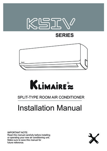
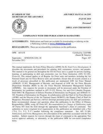
ERXW WKH FRQWUROV RQ WKH DLU FRQGLWLRQHU³ HDW &RRO 0RGHOVAppearance may erOn/OffAir Conditioner ControlsControlsRemote ControlLights beside the touch pads on the air conditionercontrol panel indicate the selected settings.1. ON/OFFTurns air conditioner on and off.2. DisplayDisplays the temperature setting. Displays hours whensetting the timer.6. TIMER21³When the air conditioner is off, it can be set toautomatically turn on in half an hour to 24 hours at itsprevious setting. Each touch will set the time in half hoursup to 10 and then in hours up to 24.3. MODETo cancel the On Timer, press the ON pad until “CL”appears. Then wait until the display turns off.4. TEMP Increase /Decrease – Pads2))³When the air conditioner is on, it can be set toautomatically turn off in half an hour to 24 hours. Eachtouch will set the time in half hours up to 10 and then inhours up to 24.On the air conditioner controls, use to set COOL, HEAT orFAN mode. Indicator lights on the air conditioner controlswill show the mode selected.Use to set temperature when in COOL or HEAT mode.5. FAN SpeedsUse to set the fan speed at LOW or HIGH. Indicator lightswill show the speed selected.To cancel the Off Timer, press the OFF pad until “CL”appears and wait for the set temperature to be displayed.The unit will now resume normal operation.7. Remote Control Signal ReceiverNOTE: When the air conditioner is turned on, it willautomatically start in the setting last used.Remote Control To ensure proper operation, aim the remote control at thesignal receiver on the air conditioner. Make sure nothing is between the air conditioner and theremote control that could block the signal. The remote control signal has a range of up to 21 feet. 0DNH VXUH EDWWHULHV DUH IUHVK DQG LQVWDOOHG FRUUHFWO\³VHH the Care and Cleaning section.6
COOL MODERemote Control1. Press COOL pad.2. Press LOW or HIGH pads to set desired fan speed.3. Press the ,1&5( 6( '(&5( 6( ² pads to set the desiredtemperature 60 F to 85 F in 1 F increments.Control PanelSet the thermostat at a higher number and the indoor air will becomewarmer.NOTE: If the air conditioner is off and is then turned on while set toCOOL, it will take approximately 3 minutes for the compressor to startand cooling to begin.Cooling Descriptions1. Press the MODE pad until the COOL indicator light is lit.)RU 1RUPDO &RROLQJ³Select the COOL mode and HIGH fan with amiddle set temperature.2. Press the FAN pad until HIGH or LOW indicator light is lit for desiredfan speed.)RU 0D[LPXP &RROLQJ³Select the COOL mode and HIGH fan with alower set temperature.3. Press the ,1&5( 6( '(&5( 6( ² pads to set the desiredtemperature 60 F to 85 F in 1 F increments.)RU 4XLHWHU DQG 1LJKWWLPH &RROLQJ³Select the COOL mode and LOWfan with a middle set temperature.A thermostat is used to maintain the room temperature. Thecompressor will cycle on and off to keep the room at the set level ofcomfort. Set the thermostat at a lower number and the indoor air willbecome cooler.NOTE: There will be a 3-minute delay between setting changes suchas COOL to OFF and back to COOL.HEAT MODERemote Control1. Press HEAT pad.2. Press LOW or HIGH pads to set desired fan speed.3. Press the ,1&5( 6( '(&5( 6( ² pads to set the desiredtemperature 60 F to 85 F in 1 F increments.Control PanelSet the thermostat at a lower number and the indoor air will becomecooler.NOTE: If the air conditioner is off and is then turned on while set toHEAT, it will take approximately 1 minute for the heater to start andheating to begin.Heating Descriptions1. Press the MODE pad until the HEAT indicator light is lit.)RU 1RUPDO HDWLQJ³Select the Heat mode and HIGH fan with amiddle set temperature.2. Press the FAN pad until HIGH or LOW indicator light is lit for desiredfan speed.)RU 0D[LPXP HDWLQJ³Select the HEAT mode and HIGH fan with ahigher set temperature.3. Press the ,1&5( 6( '(&5( 6( ² pads to set the desiredtemperature 60 F to 85 F in 1 F increments.)RU 4XLHWHU DQG 1LJKWWLPH HDWLQJ³Select the HEAT mode and LOWfan with a middle set temperature.A thermostat is used to maintain the room temperature. The heater willcycle on and off to keep the room at the set level of comfort. Set thethermostat at a higher number and the indoor air will become warmer.FANUse the FAN to provide air circulation and filtering without cooling orheating. Since fan only settings do not provide cooling or heating, atemperature setting will not be displayed.Remote ControlPress FAN pad. Press LOW or HIGH pads to set desired fan speed.Control PanelPress the MODE pad until the FAN indicator light is lit and the LOW orHIGH indicator light is lit for the desired fan speed.7
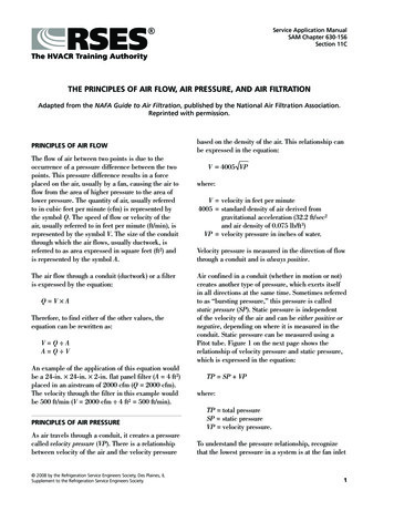
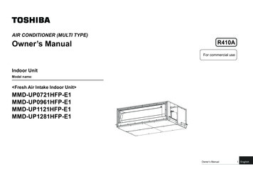
About the controls on the air conditionerVent ControlThe vent control is located behind the front grille on the right side of theair discharge area. When CLOSED, only the air inside the room will becirculated and conditioned. When OPEN, the vent allows outdoor freshair exchange.The unit leaves the factory set at the CLOSE position.Locating holeTo open or close the vent:1. Remove the front grille.2. Remove the vent card screw.3. Remove vent card, turn it over and replace it by locating rear hole incard over locating pin inside air discharge and reattaching screw atfront.Screw holeLocating holeScrew holeOPEN position(Mesh end toward back)CLOSE position(Mesh end toward front)Air DirectionHorizontal louverson the front grille let youcontrol the air direction up anddown.Remove the front grilleto adjust the verticallouvers side-to-sideto direct the air leftor right.Cool Only ModelsAuxiliary Controls – Dip Switches (location varies by model)Fan Cycle/Continuous - CoolONThe auxiliary dip switch controls are located behind theURRP FDELQHW³DV VKRZQ LQ WKLV ILJXUH COOLFANThe owner is responsible for checking switches andensuring they are in the desired position.HIGHMEDONMODEOFFTIMERON OFFTEMPSLEEP- ONOFFFilter ReminderFunctionFan Cycle/Continuous - CoolFan Cycle/Continuous - CoolONWhen this switch is enabled (RIGHT), it allows the indoorfan to cycle on/off with the compressor. When thisswitch is disabled (LEFT), it allows the indoor fan to runcontinuously. The default setting is right (fan cycle).Filter Reminder FuntionHeat/Cool ModelsAuxiliary Controls – Dip Switches (location varies by model)The auxiliary dip switch controls are located behind theURRP FDELQHW³DV VKRZQ LQ WKLV ILJXUH The owner is responsible for checking switches andensuring they are in the desired position.8Filter Reminder FunctionONWhen this switch is enabled (RIGHT), an LED will lightup the user interface after 250 of accumulated fan runtime. It serves as a reminder to clean the filter. Whenthis switch is disabled (LEFT), the function is disabled.The default setting is right (enabled).Fan Cycle/Continuous - CoolFan Cycle/Continuous - HeatClass 2No function (reservedfor future use)
Fan Cycle/Continuous - CoolWhen this switch is enabled (UP), it allows the indoor fan to cycleon/off with the compressor. When this switch is disabled (DOWN),it allows the indoor fan to run continuously. The default setting isDOWN (continuous).Fan Cycle/Continuous - CoolFan Cycle/Continuous - HeatFan Cycle/Continuous - HeatWhen this switch is enabled (UP), it allows the indoor fan to cycleon/off with the heater operation. When this switch is disabled(DOWN), it allows the indoor fan to run continuously. The defaultsetting is UP (cyclic).Class 2 - Remote ThermostatClass 2When this switch is enabled (UP), it allows the unit to operate witha Class 2 Remote Control Wall Thermostat. The unit controls aredisabled. The default setting is DOWN (disabled).Terminal Connections Remote Thermostat - Class 2 (on some models)The controls are located under a plastic cover behind the frontgrille.Terminalconnectionslocationunder frontgrille1. Remove the front grille. See the Front Grille section of Careand Cleaning.2. Remove the screws securing the plastic cover over the wiringconnections. Set aside screws and plastic cover.3. To make wiring connections, insert the wires into the bottomof the terminals and tighten screws securely.4. After all desired connections have been made, replace theplastic cover and front grille.The owner is responsible for making all connections and settingthe appropriate dip switches.When connected, the unit will be controlled by a remotethermostat.NOTE: The number 3 dip switch must be in the enabled (UP)position to activate the remote thermostat. (See the installationinstructions supplied with the remote thermostat.)IMPORTANT:The thermostat connections provide 24 V AC only.If using a digital/electronic wall thermostat, ensure it iscompatible with 24 VAC signal. See the Installation Instructionsfor the wall thermostat.NOTICE:Damage to a wall thermostat or to the electronics can resultfrom improper connections. Special care must be used inconnecting the wires. No line voltage connections should bemade to any circuit. Isolate all wires in building from line voltage.Red - 24 V AC onlyGreen - Low Speed FanGreen - High Speed FanNo Function(reserved for furture use)Yellow - CompressorWhite - HeaterCommon - GroundNo Function(reserved for furture use)9
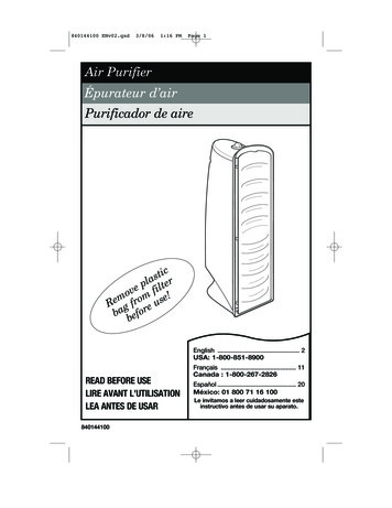
Care and cleaning of the air conditioner.Grille and CaseTurn the air conditioner off and remove the plug from thewall outlet before cleaning.To clean, use water and a mild detergent.Do not use bleach or abrasives.Outdoor CoilsThe coils on the outdoor side of the air conditioner should bechecked regularly.If they are clogged with dirt or soot they may be professionallysteam cleaned, a service available through your GE serviceoutlet.Front GrilleThe front grille can be removed for more thorough cleaning andto locate the model and serial numbers on the front of the basepan.3. Pull the grille out from the bottom and lift upfrom the tabs on the top of the case.GrilleTo remove:1. Pull the filter out.2. Remove the two grille screws.TabOn some modelsTo replace:Hook the tabs on the front grille even with the tabs on the caseand snap into place.On some modelsReplace the screws and filter.GrilleTab10
To maintain optimum performance, clean the filter at least every 30 days.Air FilterFRONTFRONTTo remove the air filter, on other models:Pull it down.'LUW\ ILOWHU³1HHGV FOHDQLQJ &ORJJHG ILOWHU³*UHDWO\ reduces cooling, heatingand airflow.Turn the air conditioner off before cleaning.The most important thing you can do to maintain the airconditioner is to clean the filter at least every 30 days. A cloggedfilter reduces cooling, heating and air flow.Keeping the air filter clean will: Decrease cost of operation. Save energy.To replace the air filter:Replace the clean filter by pushing it backinto place. Prevent clogged heat exchanger coils. Reduce the risk of premature component failure.To clean the air filters: Vacuum off the heavy soil. Run water through the filters. Dry thoroughly before replacing.To remove the air filter, on some models:Carefully pull the tab forward, up and out.NOTICE: Do not operate the air conditioner withoutthe filter in place. If a filter becomes torn or damaged itshould be replaced immediately.Operating without the filter in place or with a damaged filterwill allow dirt and dust to reach the indoor coil and reduce thecooling, heating, airflow and efficiency of the unit.Replacement filters are available from your salesperson, GEdealer, GE Service and Parts Center or authorized CustomerCare servicers.11
Care and cleaning of the air conditioner.How to Insert the Batteries in the Remote Control1. Remove the battery cover by sliding it according to thearrow direction.2. Insert new batteries making sure that the ( ) and (–) ofbattery are installed correctly.3. Reattach the cover by sliding it back into position.NOTES: Use 2 AAA (1.5 volt) batteries. Do not use rechargeablebatteries. Remove the batteries from the remote control if the systemis not going to be used for a long time. Do not mix old and new batteries. Do not mix alkaline,standard (carbon-zinc) or rechargeable (ni-cad, ni-mh, etc)batteries.Long Term StorageWhen the room air conditioner is not in use it is recommendedthat the unit be covered to eliminate drafts and limit energyloss.Insulated covers that mount to the front of the unit, that aredesigned to eliminate drafts and energy loss are recommended.Approximate size of indoor cover should be 26 in * 16 in. * 7 in.Unplug the unit before adding the cover. Follow covermanufacturer’s installation instruction to install cover.Cover should be removed prior to running the unit.12
InstallationInstructionsAir ConditionerQuestions? Call 800.GE.CARES (800.432.2737) or Visit our Website at: GEAppliances.comBEFORE YOU BEGINRead these instructions completelyand carefully. IMPORTANT ³ 6DYH WKHVH LQVWUXFWLRQV for local inspector’s use.IMPORTANT³ 2EVHUYH DOO JRYHUQLQJ FRGHV and ordinances. Note to Installer – Be sure to leave these instructionswith the Consumer. Note to Consumer – Keep these instructionsfor future reference. Skill level – Installation of this appliance requires basicmechanical skills. Completion time – Approximately 1 hour We recommend that two people install this product. Proper installation is the responsibility of the installer. Product failure due to improper installationis not covered under the Warranty.Air conditioner break-in periodNOTE – As with any mechanical device with movingparts, this unit will have a wear-in period. AFTERINSTALLATION, this unit should be operated for 48hours to achieve optimum efficiency.ELECTRICAL REQUIREMENTSWARNINGRisk of electric shock. Can cause injury or death.This appliance must be properly grounded. Wherea 2-prong wall outlet is encountered, it is yourresponsibility and obligation to have it replacedwith a properly grounded 3-prong outlet.Some models require a 115/120-volt a.c.,60-Hz grounded outlet protected with a15-amp time delay fuse or circuit breaker.The 3-prong grounding plug minimizes the possibility ofelectric shock hazard. If the wall outlet you plan to useis only a 2-prong outlet, it is your responsibility to have itreplaced with a properly grounded 3-prong wall outlet.Do not, under any circumstances, cut or removethe third (ground) prong from the power cord.Do not change the plug on the power cord of thisair conditioner.Aluminum house wiring may present specialSUREOHPV³FRQVXOW D TXDOLILHG HOHFWULFLDQ Some models require 230/208-volt a.c., protectedwith a time delay fuse or circuit breaker. Thesemodels should be installed on their own singlebranch circuit for best performance and to preventoverloading house or apartment wiring circuits,which could cause a possible fire hazard fromoverheating wires.IMPORTANT!GE strongly recommends the removal of the old wall caseDQG WKH LQVWDOODWLRQ RI D QHZ *( :DOO &DVH ,I \RX '2 127 use a GE Wall Case, you run the risk of poor performanceor product failure. This is not covered under the terms of theGE warranty.13
Installation InstructionsRead these instructions completely and carefully.Power cord may include a current interrupter device.A test and reset button is provided on the plug case.The device should be tested on a periodic basis by firstpressing the TEST button and then the RESET button.If the TEST button does not trip or if the RESET buttonwill not stay engaged, discontinue use of the airconditioner and contact a qualified service technician.722/6 28 0 1(('Phillips-headscrewdriverDrillRuler or Tape MeasureScissors or knifeHand or Saber SawPencilAdjustable WrenchLevelGE KIT NUMBERSUSE GE . ,7 180%(5 )25 RAB46A ,46,Use these kits for all GE47A, 47, 48A, models and other brands48B & 48not listedRAK65A1All GE ModelsRAK690RAB36, 37, 38, 46, 47 or 48(J-Chassis)RAG13RAB36, 37, 38, 46, 47 or 48(J-Chassis)RAG14ERAB36, 37, 38, 46, 47 or 48(J-Chassis)'(6&5,37,21Standard wall case for “J” model chassis. RAG13 stampedaluminum exterior grille included. Remove the existing caseand replace.Kit for window installation.If you attach a custom architectural outdoor grille, use this kitto ensure proper airflow.Standard aluminum exterior grille (included with RAB46, 47, 48,RAB46A, 47A, 48A, and 48B wall cases).Architectural louvered exterior grille. ' &RPSOLDQFHOperation byRemote ControlOperation atControl PanelOperation byThermostat14A Remote Control device is shipped with GE Built-In Air Conditioners. When operated by Remote Control GE Built-in ACs meet all federal ADA compliance requirements.GE Built In Air Conditioners intended to be operated at the control panel meet federal ADAcompliance requirements when installed so that the controls are more than 15” from groundand less than 48” from the ground.GE Air Conditioners intended to be operated via a wall thermostat meet federal ADA compliance requirements when used in conjunction with an ADA compliant wall thermostat mountedmore than 15” and less than 48” from the ground.
Installation Instructions,167 //,1* - 02'(/ ,1 1 (;,67,1* : // & 6(Read these instructions completely and carefully.1 5(029( // 6 ,33,1* 0 7(5, / ,) 35(6(17 ,16,'( ,5 &21',7,21(5 NEXT TO COMPRESSOR2 R(029( 7 ( ),/7(5 1' )5217 *5,//(Remove the two screws behind the filter then removethe front grille.3 & 5()8// 6/,'( ,5 &21',7,21(5 INTO CASEMake sure that the tubing on the unit doesnot touch the wall case and that the caseinstallation is secure.4 5(,167 // /2&.,1* 3/ 7( :,7 7 % %( ,1' : // & 6( )/ 1*( 7,* 7(1 SCREWLockingplateTightenscrew5 77 & )5217 *5,//(An opening for the power cord is on the bottomof the front grille.15
Installation Instructions,167 //,1* 7 528* 7 ( : //Read these instructions completely and carefully.3 SUPPORT REQUIREMENTS FOR AIR1 PREPARE OPENING IN WALLMake certain a wall receptacle is available closeto the hole location or make arrangements to installa receptacle.The cord length for the 115-volt models is 72sto the right and 47s to the left.For the 230/208-volt models the cord length is 65sto the right and 39s to the left.MINIMUM),1,6 ('OPENING ',0(16,216 &21',7,21(5Mortar between the case and the brick wall aroundthe case may be undercut at about 45 forimproved caulking.InsideTop of case & 6( ',0(16,216 HLJKW :LGWK HLJKW :LGWK 'HSWK 153ø4s 26 ø s 18 15 ø s 26 ø s581 1616s *Dimensions may needto be increased to fitunique situations in thefield if using case angles.2 SUPPORT REQUIREMENTS FOR AIR&21',7,21(5The air conditioner wall case may be installedwith 1/4s min. extension out from the inside wallor with 1/4s min. extension out from the outside wall.The finished sides of the opening should be structuralwall members./LQWHO ² Use a lintel in brick veneer and brickand block types of wall to support the bricksor blocks above the opening. Do not allow the wallcase to be used in lieu of a lintel.)ODVKLQJ ² Install flashing (drip rail) as shownto prevent water from dripping inside the walland down the outside of the building.Brick veneerLintel angle(if required)Caulking(o
On the air conditioner controls, use to set Cool or Fan mode at High, Med or Low fan speed. Indicator lights on the air conditioner controls will show the mode and fan speed selected. 4. Temp Increase /Decrease - Pads Use to set temperature when in COOL mode. 5. Fan Speeds Use to set the fan speed at Low, Med or High. 6. Delay Hrs 2Q³When .