Transcription
EE 740 – Transmission LinesSpring 2013
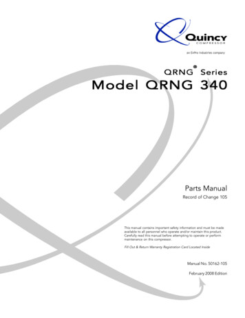
US Power Transmission Grid
Physical Characteristics – underground cables Cable lines are designed to be placed underground or underwater. The conductors are insulated from one another andsurrounded by protective sheath. Cable lines are more expensive and harder to maintain.They also have capacitance problem – not suitable for longdistance.
High Voltage Power Lines (overhead) Common voltages in north America: 138, 230, 345, 500, 765 kV Bundled conductors are used in extra-high voltage lines Stranded instead of solid conductors are used.
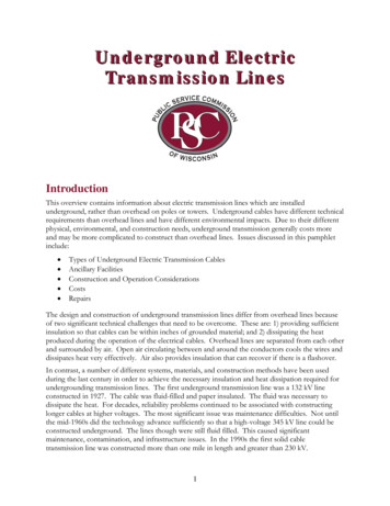
HVDC Transmission Because of the large fixed costnecessary to convert ac to dc andthen back to ac, dc transmission isonly practical in specializedapplications– long distance overhead powertransfer ( 400 miles)– long underwater cable powertransfer– providing an asynchronous meansof joining different power systems.
Electrical Characteristics Transmission lines are characterized by a series resistance,inductance, and shunt capacitance per unit length. These values determine the power-carrying capacity of thetransmission line and the voltage drop across it at full load. The DC resistance of a conductor is expressed in terms ofresistively, length and cross sectional area as follows:
Cable resistance The resistively increases linearly with temperature over normalrange of temperatures. If the resistively at one temperature and material temperatureconstant are known, the resistively at another temperature canbe found by
Cable Resistance AC resistance of a conductor is always higher than its DCresistance due to the skin effect forcing more current flow nearthe outer surface of the conductor. The higher the frequency ofcurrent, the more noticeable skin effect would be. Wire manufacturers usually supply tables of resistance per unitlength at common frequencies (50 and 60 Hz). Therefore, theresistance can be determined from such tables.
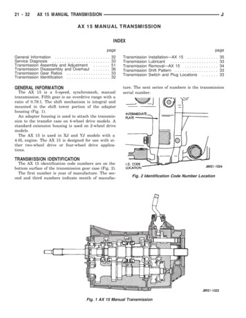
ACSR Conductor Table DataGeometric Mean RadiusInductive and CapacitiveReactance for 1-foot Spacing
Line inductance
Remarks on line inductance The greater the spacing between the phases of atransmission line, the greater the inductance of the line.– Since the phases of a high-voltage overhead transmission line must bespaced further apart to ensure proper insulation, a high-voltage line willhave a higher inductance than a low-voltage line.– Since the spacing between lines in buried cables is very small, seriesinductance of cables is much smaller than the inductance of overhead lines The greater the radius of the conductors in a transmissionline, the lower the inductance of the line. In practicaltransmission lines, instead of using heavy and inflexible conductors oflarge radii, two and more conductors are bundled together toapproximate a large diameter conductor, and reduce corona loss.GMR2 GMR.dGMR3 3 GMR.d 2GMR4 1.09 4 GMR.d 3
Inductance of 3-phase transmission line
Shunt capacitance Since a voltage V is applied to a pair of conductors separated bya dielectric (air), charges q of equal magnitude but oppositesign will accumulate on the conductors. Capacitance C betweenthe two conductors is defined byqC V The capacitance of a single-phase transmission line is given by(see derivation in the book): (ε 8.85 x 10⁻¹² F/m)
Capacitance of 3-phase transmission lineGMDX C 0.02965 ln( M .mi)r
Remarks on line capacitance1. The greater the spacing between the phases of atransmission line, the lower the capacitance of the line.––Since the phases of a high-voltage overhead transmission linemust be spaced further apart to ensure proper insulation, a highvoltage line will have a lower capacitance than a low-voltage line.Since the spacing between lines in buried cables is very small,shunt capacitance of cables is much larger than the capacitanceof overhead lines.2. The greater the radius of the conductors in a transmissionline, the higher the capacitance of the line. Therefore,bundling increases the capacitance.
Use of Tables Inductive reactance (in Ω/mi):X L 0.1213 lnGMD1 0.1213 ln 0.1213 ln GMDGMRGMR– The first term is defined as Xa: the inductive reactance at 1-foot spacing– The second term is defined as Xd : the inductive reactance spacing factor– Both of the above components are already calculated in Table A.3 & A.4 Capacitive reactance (in MΩ.mi):X C 0.02965 lnGMD1 0.02965 ln 0.02965 ln GMDrr– The first term is defined as X’a: the capacitive reactance at 1-foot spacing– The second term is defined as X’d : the capacitive reactance spacing factor– Both of the above components are already calculated in Table A.3 & A.5
Short line model Overhead transmission lines shorter than 50 miles can bemodeled as a series resistance and inductance, since theshunt capacitance can be neglected over short distances. The total series resistance and series reactance can becalculated as where r, x are resistance and reactance per unit length and dis the length of the transmission line.
Short line model Two-port network model: The equation is similar to that of a synchronous generator andtransformer (w/o shunt impedance)
Short lineVoltage Regulation:1. If lagging (inductive) loads are added at the end of aline, the voltage at the end of the transmission linedecreases significantly – large positive VR.2. If unity-PF (resistive) loads are added at the end of aline, the voltage at the end of the transmission linedecreases slightly – small positive VR.3. If leading (capacitive) loads are added at the end of aline, the voltage at the end of the transmission lineincreases – negative VR.
Short line – simplified If the resistance of the line is ignored, then Therefore, the power flow through a transmission line depends onthe angle between the input and output voltages. Maximum power flow occurs when δ 90o. Notes:– The maximum power handling capability of a transmission line is afunction of the square of its voltage.– The maximum power handling capability of a transmission line isinversely proportional to its series reactance (some very long linesinclude series capacitors to reduce the total series reactance).– The angle δ controls the power flow through the line. Hence, it ispossible to control power flow by placing a phase-shifting transformer.
Line Characteristics To prevents excessive voltage variations in a power system, theratio of the magnitude of the receiving end voltage to themagnitude of the ending end voltage is generally within0.95 VS/VR 1.05 The angle δ in a transmission line should typically be 30o toensure that the power flow in the transmission line is well belowthe static stability limit. Any of these limits can be more or less important in differentcircumstances.– In short lines, where series reactance X is relatively small, theresistive heating usually limits the power that the line can supply.– In longer lines operating at lagging power factors, the voltage dropacross the line is usually the limiting factor.– In longer lines operating at leading power factors, the maximumangle δ can be the limiting f actor.
Example A line with reactance X and negligible resistance supplies apure resistive load from a fixed source VS. Determine themaximum power transfer, and the load voltage VR at whichthis occurs. (Hint: recall the maximum power transfer theoremfrom your basic circuits course)
Medium Line (50-150 mi) the shunt admittance must be included in calculations. However, thetotal admittance is usually modeled (π model) as two capacitors ofequal values (each corresponding to a half of total admittance)placed at the sending and receiving ends. The total series resistance and series reactance are calculated asbefore. Similarly, the total shunt admittance is given by where y is the shunt admittance per unit length and d is the lengthof the transmission line.
Medium Line Two-port network:
Long Lines ( 150 mi) For long lines, both the shunt capacitance and the seriesimpedance must be treated as distributed quantities. Thevoltages and currents on the line are found by solving differentialequations of the line. However, it is possible to model a long transmission line as a πmodel with a modified series impedance Z’ and a modified shuntadmittance Y’ and to perform calculations on that model usingABCD constants. These modified values arewhere the propagation constant is defined by
Surge Impedance Loading The surge impedance of a line is defined asZC z / y L / C Surge Impedance Loading (SIL) is the power delivered by aline to a pure resistive load that is equal to its surgeimpedance:V 2VL2SIL 3 MWL/CL/C Under such loading, the line consumes as much reactivepower as it generates and the terminal voltages are equalto each other. Power system engineers sometime find it convenient toexpress the power transmitted by a line in terms of perunit of SIL.
Reactive Power Generation/Consumption Note that a transmission line both absorbs and generatesreactive power: Under light load, the line generates more reactivepower than it consumes. Under “surge impedance loading”, the line generatesand consumes the same amount of reactive power. Under heavy load, the line absorbs more reactivepower than it generates.
Input/Output Power and efficiency Input powers Output powers Efficiency
Power Flow Through a Transmission Line LetA A , B B , VS VS , VR VR 0o Then the complex power at the receiving end is given byPR jQR VR I R* VS VRB ( ) A VRB2 ( )
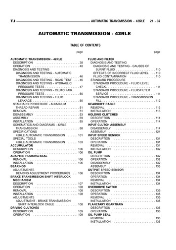
Power Diagram (by shifting origin of coordinate axes) For fixed values of both voltage and as the load changes, point kmoves on a circle of center n.– Any change in PR will require a change in QR.– The limit of the power that can be transmitted occurs whenβ δ.– The maximum power transfer isPR.max VS VRB A VRB2cos( )– This above requires a large leading current.– Normally, δ 35o 0.95 VSVR 1.05
Long line series and shunt compensation Shunt reactors are used to compensate the line shuntcapacitance under light load or no load to regulate voltage. Series capacitors are often used to compensate the lineinductive reactance in order to transfer more power.
Problems (Chap 6) 8, 16, 20, 23, 25
Electrical Characteristics Transmission lines are characterized by a series resistance, inductance, and shunt capacitance per unit length. These values determine the power-carrying capacity of the transmission line and the voltage drop across it at full load. The DC resistance of a conductor is expressed in terms of