Transcription
21STSYMPOSIUM OF THE INDUSTRIAL APPLICATION OF GAS TURBINES COMMITTEEBANFF, ALBERTA, CANADAOCTOBER 201515-IAGT-102FLEXIBLE PACKAGE SOLUTIONS FORSIEMENS SGT-800Tobias Kiuru*, Mikael holm@siemens.comKeywords: SGT-800, Gas Turbine, Gas Turbine Package, Flexible, Single lift,ModularizedAbstractThis paper will describe the flexible package solutions for SIEMENS SGT-800 gasturbine. A brief overview of the gas turbine and its performance will be given.The Siemens gas turbine SGT-800 is now available with two different packages,Classic package and Single lift package. In the Classic package, the generator is placedon foundation and in the Single lift package the gas turbine, gear box and generator areplaced on a common base frame. Driving the development for the Single lift packagehave been the customers demand for more flexible installation requirements; smallfootprint, short installation and commissioning time at site, high availability as well asenhanced string test possibilities. This has been achieved by rearranging the auxiliaryunits of the SGT-800 Classic package and fitting them together with the turbine string ona common base frame. No changes have been made to the well proven and robust SGT800 core engine; the auxiliary systems still supports the same excellent capabilities forfuel and operational flexibility.The IAGT Committee is sponsored by the Canadian Gas Association and supported by the National ResearchCouncil Canada. The IAGT Committee is not responsible for statements or opinions advanced in the technicalpapers or at the Symposium or meeting discussions.
1IntroductionSiemens Industrial Turbomachinery AB, Finspong Sweden has introduced a single liftpackage arrangement for the SGT-800 gas turbine product. Driving this development hasbeen the customers need for more flexible installation, offering reduced footprint,installation and commissioning times. In addition to package layout changes the gasturbine product has been uprated, offering 53MWe of electrical power.1.1Package ArrangementsThe need for a SGT-800 Single Lift package is driven by the need for small footprint,reduced time for installation and commissioning (especially required in harsh and remoteareas) as well as maintaining high availability along with improved factory build options,such as string test possibilities (combined test of all contract equipment). This has beenachieved by rearranging the auxiliary units of the SGT-800 Classic package and fittingthem together with the generator onto a common base frame.1.2The SGT-800 Gas TurbineSGT-800 is the largest industrial gas turbine manufactured by Siemens IndustrialTurbomachinery AB. Launched in 1997 as a 43 MW machine named GTX100 [1], theSGT-800 was soon re-rated to 45 MW and in 2007 further enhanced to 47.5 MW with37.7% simple cycle efficiency [2][3] and close to 55% combined cycle operation efficiencyin a 2x1 configuration, By including cogeneration (district heating) the efficiency furtherincreased to more than 90% [3]. Siemens has continued the stepwise evolutionarydevelopment based on experience and proven design solutions in order to always assurehigh reliability. 2010 saw the release of a new output rating, 50.5 MW with a 38.3%simple cycle electrical efficiency (ISO) and a 2x1 combined-cycle performance of 55%[3]. In 2015 Siemens released the product with revised output of 53.0 MW and with39.0% simple cycle efficiency and 56% combined cycle efficiency in 2x1configuration[4].The SGT-800 is today available to the market in the three different ratings 47.5 MW,50.5 MW and 53.0 MW.Up to June 2015 270 SGT-800 units have been sold and have accumulated morethan 3.3 million Equivalent Operating Hours (EOH)1 with the fleet leader exceeding morethan 110,000 EOH.1EOH Equivalent Operating Hours – Normalized operation taking into account the impact of specific operationconditions on maintenance intervals2
2SGT-800 Package SolutionsSiemens SGT-800 is now available in two different packages; Single lift package andClassic package. The Classic package was originally developed for the Industrial PowerGeneration market with strong focus on in-situ maintenance and low cost of includedpackage material, while the Single Lift package has been developed with the main focusto reduce the package footprint and to minimize the installation and commissioning timeat site. This gives the customer the opportunity to spend less capital cost for foundationwork, installation work and related the costs. With the high availability together with theenhanced string test possibilities the aim has been to give the customer the opportunityto ship the unit fully tested directly to the site. With excellent combined cycle efficiency,reliable Dry Low Emission (DLE) fuel system, high reliability and availability, the SGT-800has developed into a well-accepted mature product, with a few enhancements furtherdescribed in section 3.2.1.2. The interest in the product has continued to increase fromPower Generation customers as well as O&G customers.Below a short description of the Classic package will be given as a reference to theSingle lift package.2.1Classic PackageWhen the SGT-800 was launched the package arrangement was a traditional gasturbine package, similar to the larger frame gas turbines, with a skid-mounted packageincorporating the gas turbine and gearbox on a single base frame, or with the gearboxplaced directly on the foundation. Mechanical auxiliary systems are separately mountedon an external skid placed close to the gas turbine. An enclosure covers the gas turbineand the auxiliary system to create a safe operating environment for the gas turbine aswell as protect the surroundings from noise emissions.Turbine controls, generator control panel, motor control center for package motorsand variable-speed drive for starter motor are normally supplied in an external controlmodule or as separate items.3Single Lift PackageMain features and the design background of the Single Lift package will be detailed inthe following sections.3.1BackgroundThe SGT-800 Single Lift package has been designed in order to meet a variety ofcustomers’ market challenges in the coming years: Operate gas turbines in a more remote and harsh environment Operate gas turbines on non-standard gas fuel in order to monetize strandedgas assets Provide reliable energy to various energy consumers Provide low carbon energy at the lowest possible cost3
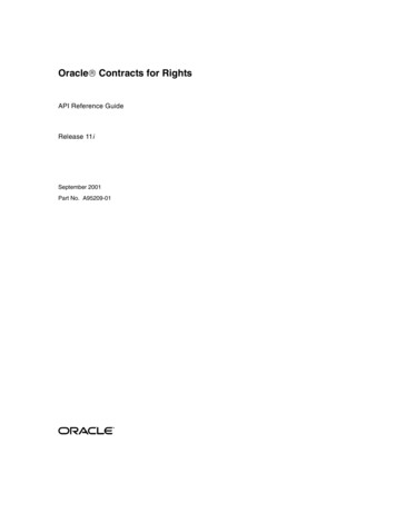
3.2Single Lift Package IntroductionWith the aim to meet the above variety of future market challenges, the design of theSingle lift package is a further development of the SGT-800 Classic package, focus of thedevelopment have been customer demands for more flexible installation requirementsthat a smaller small footprint will give and short installation and commissioning time atsite together with high availability as well as enhanced string test possibilities. The designof the package had to be designed in such a way that it not only gains O&G acceptance,onshore & offshore, but also that it will retain its acceptance from the Power Generationcustomers by having high exhaust heat energy and excellent combined cycleperformance. This has been achieved by rearranging the auxiliary units of the SGT-800Classic package and fitting them together with the turbine string on a common baseframe. No changes have been made to the well proven and robust SGT-800 core engineduring the design of the Single Lift package and the package can be equipped with anyof the available core engine versions as presented in chapter 3.2.1.1 below. The auxiliarysystems still supports the same excellent capabilities for fuel and operational flexibility.With the relocation of the auxiliary systems to the Single Lift skid Siemens hasreduced the installation requirement of a large plot space to a minimum. The Single Liftpackage only need 115m2 plot space for the installation compared to 210 m2 for theClassic package which is a reduction with more than 50%. This reduced need for plotspace, by using the SGT-800 Single Lift design, gives the customer the benefit of utilizingbrown and green fields more efficiently by utilizing the plot space to the optimum leadingto that less work is needed for exploration and excavation.3.2.1 SGT-800 Core Engine OverviewSGT-800 is a single shaft gas turbine, Figure 1, and is used for power generation.The three stage power turbine is bolted to the compressor. The compressor has 15stages and a pressure ratio of 21.4:1. Three variable guide vanes and two compressorbleeds that are used during start-up. During load operation, the variable guiede vanesare sued for mass flow control. Electron beam welding is used to manufacture thecompressor rotor, forming a solid rotor body.Figure 1: SGT-800 Gas turbine.4
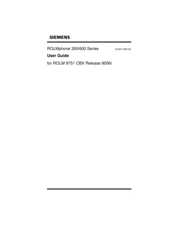
The compressor can be optimized for either normal or hot climate. The hot ambientmatched compressor will maximize power output and efficiency at higher ambient. This isachieved by selecting an optional set of stator compressor stages 3 to 15 only.The combustion system consists of an annular type combustor system with 30 DLEburners.The turbine section of the SGT-800 consists of the three-stage high-efficiency turbine.The stage 1 vane and blade have both film and convective cooling, stage 2 vane andblade have convective cooling and stage 3 is uncooled. . Thermal barrier coating is usedfor reduced cooling-air consumption in stage 1 and 2. The disks are bolted to the rotorwith tie-bolts.3.2.1.1 Evolutionary DevelopmentThe SGT-800 gas turbine since its introduction has been optimized leading toincreased power output, improved efficiency and mass flow. All upgrades have beenbased on extensive full-scale engine validation testing and excellent operationalfeedback. The latest upgrade, driven by the continues requirement for higher poweroutput and heat rate with better efficiency, has been achieved through optimized and restaggered first stage compressor blades which increase both efficiency and mass flow;optimized cooling layout of turbine guide vanes; and adjusted clearances in turbine stage1 and 2. Only minor changes of the machining of four stationary components have beenrequired to exploit the built-in performance tuning potential in the turbine section. Nochanges have been made to castings or materials and importantly the outlet temperaturefrom the combustor remains the same. All improved components are fully retrofittablewithin the existing 50.5 MW series.3.2.2 Single Lift SkidTo facilitate easy installation in various environments, for example remote areas orharsh environments, the single lift package is developed as a complete skid-mountedpackage with single lift capacity of the complete train, i.e. gas turbine, gearbox,generator, mechanical auxiliary systems and enclosure, see Figure 2.By having the auxiliaries relocated to the common base frame the customer alsobenefits from that the cost for civil and foundation work is reduced as well as installationand commissioning costs compared to the Classic package.5
Figure 2: SGT-800 Single Lift Skid.The skid is a welded construction comprising two parallel HEA900 I-beams with twolifting bollards located on the each long side of the package. Aside from facilitatingsupport-; for the gas turbine the skid also have an integral wet skid for the lube oilsystem. This enables the smallest possible footprint of the package, as well as a highdegree of completion from workshop with a minimum of installation needed at site.Installation to the foundation can be made either by multi point for onshore installations orif a less complex foundation is required, typically offshore installations, a three pointmount can be selected which then adds an under base frame.The decision to go with a rigid base frame and not a bolted design was driven by tworeasons. A design with split skids bolted together would lead to the customer needing tospend valuable time on site during the installation for alignment of two skids at thefoundation as well as aligning the generator with the gas turbine. A bolted design also6
requires a very complex bolt interface between two skids in order to handle the deflectionand torsional stresses during operation.To be able to adapt to different requirements during installation of the package, theskid is designed in such a way that it allows for the package to be either lifted on to thefoundation or by jacking and sliding the package into position on to the foundation.3.2.3 Lube Oil Supply UnitSingle Lift package has a lube oil supply unit with three lube oil pumps, lube oil mistfan and lube oil filters that is located on top of the integrated wet skid together with thenecessary instrumentation and control equipment. Main components are installed as amodule while lube oil heaters and jacking oil pump are installed separately. To maintainthe high availability from the classic package same components are used for the lube oilsupply unit in both Classic package and Single Lift package. By arranging thecomponents of the lube oil unit in such a way they can easily be accessed, either fromthe outside or from the platforms inside the package, the serviceability is kept the sameas for the Classic package.3.2.4 Gas Turbine EnclosureThe enclosure is designed to be fully assembled and dressed independently and thenlifted on to the skid in the factory workshop. With this concept any and all site enclosureworks is re-located to the workshop thus minimizing the activities at site withoutextending the delivery time compared to the Classic package. To ensure easily access tothe different on-skid systems the enclosure is equipped with 6 doors for maintenancepurpose. This also provides service access to the auxiliary systems as the lube oil supplyunit and lube oil cabinet. For engine roll out folded doors are available, which can beoperated without use of tools. The customer can select either right or left side of thesound enclosure to facilitate flexible maintenance independently of the packageorientation.3.2.5 Gas Fuel SystemGas fuel systems components are common with the classic package thus maintainingthe same level reliability to the Single Lift package as well as maintaining the fuelflexibility of the Classic package. Further description to the gas fuel system capabilities isgiven in section 4.3.2.6 Electrical starter motorBoth the Classic package and the Single Lift package have the common starter motorwhich provides no impact on reliability to the new package. For the Single Lift packagethe starter motor has been relocated from a foundation installation to an installation madeon common base frame.7
3.2.7 DiffuserSingle Lift package diffuser length has been shortened by 39% and the weight by49% compared to previous versions of diffuser, without affecting the diffusor efficiency,i.e the Single Lift have the same diffuser efficiency as the Classic Package. The shorteddiffuser shortens the overall length of the Single Lift package compared to if the Classicpackage diffuser had been used for the design.To shorten the installation time on site the diffuser has been divided into two parts, adiffuser part and an exhaust duct section. This enables assembly and alignment of thediffusor in workshop before delivery while only the exhaust duct must be attached at site.Aligning both the diffuser and exhaust duct is done with adjustable rigging screws. Theshortened diffuser also have lower thermal losses and less noise emissions thanprevious diffusor designs.3.2.8 Highly Degree of CompletionWith the core engine and the auxiliary systems placed on one single skid thepossibilities are enabled to have the engine and the system assembled, installed andconnected in workshop in a controlled environment instead of at the customer site. Therelocation also enables the on-skid electrical installation, up to junction boxes placedoutside of the sound enclosure, is made in the workshop minimizing the need to enter theenclosure during site installation and commissioning. This includes both signal cabling aswell as power cables, for example the starter motor cables.Mechanically the same design philosophy has been used, meaning all customerpiping interfaces is situated outside of the skid and the sound enclosure.With the systems assembled, installed, connected and fully tested in a packageworkshop test in the workshop the Single Lift reaches a very high degree of completion ina controlled workshop environment before the shipment is made. With this highly degreeof completion the installation and commissioning times at site are kept to a minimum, aslow as 60 working days between turbine delivery to site to handover to customer, this is areduction by almost 50% from the Classic package. This short time gives the customerthe opportunity to have gas turbine installations made where installation andcommissioning windows are narrow, for example due to weather reason. This conceptalso reduces site costs, in terms of manpower, extended crane and other equipment hire.3.2.9 Enhanced String Test CapabilitiesWith the highly degree of completion and testing described above the Single Lift givesenhanced string test capabilities with the alignment already done in the workshop theequipment can be lifted or slided into test position onto the test bed without further needof alignment. With the relocation of the auxiliary systems the need for a lifting crane isminimized.As the mechanical and electrical interfaces are located outside of the package andwith a package already tested in a workshop test the string test installation is simplifiedand the time needed for the test is decreased leading to lower cost for the customer.8
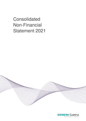
Single Lift and the Classic package use the same slave equipment for the string test,such as load banks, fuel supply, and auxiliary power system and, depending on thescope of the string test, air intake and cooling system.The customer has the option to either fully test the SGT-800 core engine in a ‘socalled’ mechanical running test or choose to fully test the entire package beforeshipment. This will allow the unit to be ready for customer operation after 60 days or lessof site installation and commissioning.3.2.10 Increased AvailabilityThe Classic package has achieved an excellent average fleet availability andreliability of 97.4% and 99.6%, respectively and a mean time between forced outage of5306 hours. A key improvement for the Single Lift package compared to the Classicpackage is the introduction of a quick core engine exchange, see Figure 3. With the quickcore engine exchange introduced its possible to exchange the core engine in 48 hoursfor either scheduled or corrective maintenance, resulting in less downtime for thecustomer. This increases the serviceability of the core engine and the availability of thepackage while it still maintains the flexibility to perform service on site or off site.Figure 3: Siemens Single Lift package with the core engine extracted4Flexible Fuel OperationBoth the Classic package and the Single Lift package uses the well proven 3rdGeneration Dry Low Emission system and share the same components allowing that thesame flexible fuel operation is kept, but for the Single Lift package, with rearrangedpiping to fit into the single lift skid. The SGT-800 combustion system uses an annularcombustor with thirty removable DLE burners installed.9
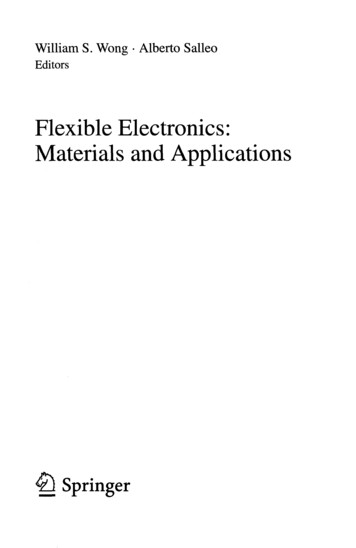
The flexibility comes from the inherent design of the simply but robust DLE systemincluding the burner. The patented DLE burner, Figure 4, consists of a split cone formingfour air slots where main gas is injected followed by a mixing section with film air holes.Near the base of the cone, central gas or main liquid is fed and intensively mixed with thecompressor air. The pilot fuel injection is positioned at the burner tip. The flame ispositioned in the burner outlet with pilot flame at the tip of the burner. During operationthe flame is controlled by fuel ratio between the pilot flow and the main gas flow. In orderto stabilize the flame during low load operation the flame is reduced corresponding to theload and the pilot flame is increased to support the main flame in order to avoid flameinstability, the opposite conditions occurs during higher load.Figure 4: The 3rd generation DLE burnerThe gas flow to pilot and main streams are controlled by two independently motoroperated control valves. Due to the system not having the complexity of burner staging itis by its design very robust. The absence of burner staging make the system verycapable of handling both load variations, as step loads and load rejections, as well as theflexibility to operate on a wide variety of fuels. The system has in full engine operationand tests proven its capability to operate on fuel gas with Wobbe index range between 22– 80 MJ/Nm3. The benefit of increased and proven fuel flexibility is clear as it allows thegas turbine owner to make full use of opportunity fuels and to supply power at low fuelcost [5].5Installation ExampleIn below sections two highlighted examples will be given where the installation ofSGT-800 Single Lift package gives valuable benefit for the customer.5.1SGT-800 Single Lift Offshore Installation ExampleThe company has developed a high efficiency combined cycle concept suitable forfixed and floating off/near shore installations. The concept can be used for installations inarctic areas as well as in various climatic areas around the globe. Below is pictured aSCC-800 4x1C concept, Figure 5, with the structure for a tempered building operating inharsh arctic conditions.10
Figure 5: SCC-800 4x1C concept for arctic installationThe concept is based on the SGT-800 Single Lift package with three point mount, avertical once through Steam Generator (minimum foot print, minimum make up waterconsumption) and a packaged condensing steam turbine. The SCC concept is availablein 1x1 up to 6x1 configurations from typically 70 to 450 MW.Installed net performance of a 2x1 power block is at ISO conditions 150 MW, atgenerator terminals, with an efficiency of 56%. Main equipment of a 2x1 configurationcan be accommodated within 70x30 meter of the main deck. Auxiliaries are normallyinstalled on a lower deck or in the void inside a barge.With the SGT-800 Single Lift fully assembled in the workshop and fully string tested atthe test beds at the fabrication yard final commissioning at site can be minimized alongwith possible risk picture at installation site.Maintenance of gas and steam turbines is done onboard, basic design incorporatenecessary service areas and handling requirement of turbine parts. With the Single Liftpackage core engine exchange in 48 hours the customer gets the highest possibleavailability of the power generating installation.With the power plant / barge built and commissioned in a yard and then shipped tosite the barge will, by the nature of its “plug&play” concept, be able to generate powerwithin 26-30 months from order.11
5.2SGT-800 Single Lift Onshore Installation ExampleProject in the Middle East area with a site simple cycle power rating requirement at anambient temperature of 50OC:A Single Lift package with the selection of a hot ambient optimized compressor offersthe customer 26% more power output and 5.8% Heat Rate reduction compared to theSGT-800 normal ambient matched compressor, Figure 6. The 26% more power gives thecustomer the possibility to install less units leading to lower capital expense andadditional savings in plot space and related savings for civil works, this in addition to thesavings made for the installation and commissioning works by selecting the Single Liftpackage over a traditional site built package.Further, the customer will benefit from the 48 hour quick core exchange with areduction by 40 days in the downtime, with an available spare core, over a period offifteen years of operation. The customer will achieve an operational benefit from theSingle Lift by increasing availability of more than 960 hours for producing power.Figure 6: SGT-800 High Ambient Temperature CapabilitySummaryWith the Single Lift package Siemens has accomplished a package that has smallfootprint is fuel flexible and have a highly degree of completion prior shipment. This givesthe customer the opportunity to reduce their cost for equipment transportation,excavation of the plot space and the site logistics needed. The package also gives theopportunity to the customer to save cost spent on labor and daily allowances as less timeis spent on installation and commissioning. The Single Lift package concept is of greatimportance in remote or harsh environment where labor can only be at site for limitedtime or where the availability of labor in the region is the limiting factor and must beefficiently utilized.12
ACKNOWLEDGMENTSThe authors would like to acknowledge Siemens Industrial Turbomachinery AB,Finspang, Sweden for the permission to publish this paper. Additionally the authorsacknowledge all Siemens employees involved in the development work during theconcept and design.References[1]Gudmundsson, B., Nilsson, U., Linder, U., Shukin, S., Afanasiev, I., Kostege, V.“Experience from the joint development of the GTX100 turbine blading”, Proceedingsof ASME International Gas Turbine and Aeroengine Congress and Exhibition 1998,ASME 98-GR-201, June 2-5, Stockholm, Sweden.[2]Shukin, S., Annerfeldt M. and Björkman, M., “Siemens SGT-800 industrial gas turbineenhanced to 47MW design modifications and operation experience”, Proceedings ofASME Turbo Expo 2008: Power for Land, Sea and Air, GT2008-50087, June 9-13,Berlin, Germany.[3]SGT-800 information in brochure available r-generation/gas-turbines/sgt800.htm[4]Siemens SGT-800 Press release, “Performance upgrade of Siemens SGT-800industrial gas turbine" available wer-gas/2015-06-sgt800.php?content[] PG[5]Andersson, M., Larsson, A., Manrique Carrera, A., ”Pentane rich fuels for standardSiemens DLE gas turbines”, Proceedings of ASME Turbo Expo 2011, GT201146099, June 6-10, Vancouver, Canada[6]Manrique, A., Andersson, M., Bonaldo, A., Larsson, A., Blomstedt, M., “Extended lowemissions capabilities of the SGT-700 DLE combustion system”, Power-Gen Europe2015, June 9-11, Amsterdam, The NetherlandsCopyrightPapers are considered part of the public domain and may appear in Symposiumhandouts, CD ROM and website postings. If there exist any restrictions on the sharing ofthe material, instructions to that effect should be provided at the time of draft submissionor otherwise consent will be considered granted. In addition, with the submission of thefinal paper, the author(s) confirm that they, and/or their company or institution, holdcopyright on all of the original material included in their paper. They also confirm theyhave obtained permission, from the copyright holder of any third party material includedin their paper, to publish it as part of their paper.13
Turbine controls, generator control panel, motor control center for package motors and variable-speed drive for starter motor are normally supplied in an external control module or as separate items. 3 Single Lift Package Main features and the design background of the Single Lift package will be detailed in the following sections. 3.1 Background