Transcription
DECK DRAINAGE SYSTEMI N S TA L L AT I O N G U I D EC R E AT E AD R Y S PAC Ebelow yo ur d e c k
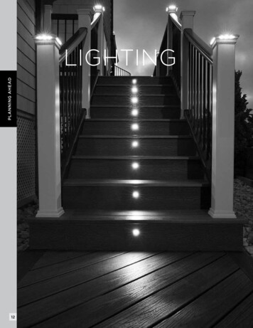
Protect the space below your deckF R O M R A I N , S U N & OT H E R E L E M E N TSWAT E R I S D I R E C T E D AWAYF R O M YO U R D E C K A N D I N TOA WAT E R D R A I N AG E S Y S T E ME X PA N D YO U RO U T D O O R L I V I N G S PAC E
DECK DRAINAGE SYSTEMI N S TA L L AT I O N G U I D EThis installation guide provides step-by-step instructions on how to install Trex RainEscapeon an elevated deck. Please read through these instructions carefully. For additional informationon how to install Trex RainEscape, please view our videos on the Trex RainEscapeYouTube channel or call a Trex RainEscape Specialist at 1-877-348-1385.1
CONTENTST R E X R A I N E S C A P E I N S TA L L AT I O N G U I D EBASIC INSTALLATIONParts . 4Tools . 4Preparation . 5Installing the Trex RainEscape Downspout . 5Types of Flashing. 6Installing the Trex RainEscape Trough . 7Tape all Seams . 9Wall Flash . 9Installing Fascia. 10Installation of a Gutter System . 10Installing Trex Rainescape Soffit Lights. 11MODIFICATIONS & SPECIAL CASESSingle Picture Frame or Breaker Board .14Double or Triple Picture Frame .14Cantilevered Downspout . 15Obstructions & Posts . 16Using the Trex RainEscape Post Flash . 16Surface Post Mount. 17Installation of a Trough Over a Double or Triple Beam . 17Modifying Downspouts for Obstructions . 17Cutting Around Downspouts and Obstructions . 18Double Extended Decks (over 19'). 18Installing Can Lighting . 19Installing Over Deck Steps. 19INSTALLATION OVER A STEEL JOIST SYSTEM . 20WARRANTY . 22FREQUENTLY ASKED QUESTIONS . 23*Refer to installation sheet for most current updates2
B E F O R E YO U B E G I NAlways consult with the local building code official prior to installing thesystem to ensure you are meeting all code and safety requirements.Trex is not responsible for improper or non-recommended installations.HELPFUL TIPSScan this QR code to view a video on designand layout considerations to keep in mindwhen installing the Trex RainEscape system.DO'SDON'TSMake all joists straight and square.Do not staple Trex RainEscape productsanywhere other than into or over floor joists,ledger, rim joists, or headers.Add outlets to gutter every 12' - 14'.Cover all joists and blocking withtrough material, then butyl tape.Cover the Trex RainEscapesystem with deck boards.Ensure the troughs anddownspouts are dry and clearof debris before applying tape.Do not use spiked hidden fasteners, or anyfastener without a flat base to provide pressureto butyl tape. Call a Trex RainEscape Specialistat 1-877-348-1385 for recommendations.Do not over drive double thread screws.Acclimate the troughbefore installing.Do not stand anywhere other than the top ofthe floor joists, ledger, rim joists, or headers.The Trex RainEscape system can not supportbody weight.Install the trough materialwith the shiny side up.Do not use nails to attach the deck boardsabove the Trex RainEscape system.HELPFUL TIPSTHE TREX RAINESCAPE SYSTEM IS MORE EASILYINSTALLED WITH TWO PEOPLE WORKING TOGETHERSNOW BUILD-UPSnow will sit on decking until it melts and then it will run through the system.LEAVESIf leaves and debris accumulate in the troughs, a standard washing or a hard rainwill clean out the system.IF THE TAPE WILL NOT STICKIn areas, such as the perimeter, brick or stucco, where the Trex RainEscape tape willnot stick, use the Trex RainEscape caulking to adhere the material.CAUTIONDo not splice trough material. If the trough material is spliced it must be replaced.Do not try to repair any damage with the Trex RainEscape tape.To estimate your materials needs or for questions, visit our websitetrexrainescape.com or contact us at 1-877-348-13853
BAS I C I NSTA L LATIO NPARTSTOOLSTROUGH - 20mil19-5/8" x 16' (49.8 cm x 4.8 M)DOWNSPOUT - 40milBASIC INSTALLATIONWALL FLASH1/4" x 1" x 25'(6.35 mm x 25.4mm x 7.62 M)CAULKING* (10.5 oz tube)STAPLE GUNCAULKING GUNREGULAR STAPLES(3/8" or longer)UTILITY KNIFETROUGH - 20mil19-5/8" x 12' 49.8 cm x 3.6 M)TAPE4" x 50'(102mm x 15.24 M)DOUBLE SIDED TAPE21/2" x 50'(63.5 mm x 15.24 M)SOFFITLIGHT4X4 POST FLASH(102 mm x 102 mm)4-5/8" (120 mm)HOLE SAW* One tube covers 25linear ft. w/1/4" beadFRAMING DETAILINSTALLATION OF THEFLAT BLOCKING AND RAILING(See pgs. 16 & 17)INSTALLDOWNSPOUTS(See pg. 5)2 x 4 FLATBLOCKCANTILEVEREDTRIPLE BEAM & FLUSHMOUNT POST(See pg. 17)INSIDE POSTMOUNTN:TIOECDIRW otOLoRF rfTE ll peWA /4" fa12 x 4 FLATBLOCKPLACE A TEMPORARYNAILER ATTACHING TOEACH JOISTINSTALLATIONOF THETROUGH(See pg. 7)4
1. PREPARATION»Read all instructions completely before beginning.» Place midspan nailer (1) or vertical blocking (1A)to keep joist straight and prevent rolling.2A12" CENTER16" CENTER10-1/4"14-1/2"» Midspan nailer can be removed when soffit orceiling is installed.10"14"5-1/4"BASIC INSTALLATION» Downspout should extend 1" into gutter: cut orextend as necessary. (2C)PLACE A TEMPORARYNAILER UNDER JOIST1ASIDE VIEWMAXIMUM DEPTH FOR TROUGH IS 4"4"2BBLOCK BELOW THETROUGH SYSTEMBLOCKING2. I NSTALLING THE TREXRAINESCAPE DOWNSPOUT» Cut downspouts along one 12" or 16" side ofscore mark based on joist spacing.» Install all downspouts along rim joist and/orledger board. Cut-out side should face opendeck bay.22CSIDE VIEWDOWNSPOUTSHOULD EXTENDABOUT 1" INTOTHE GUTTERTEAR OUT OPENINGAS MARKED ON THEDOWNSPOUT. (INCOOLER WEATHER USEA UTILITY KNIFE)5
3. THREE TYPES OF FLASHING:No Flashing with Brick or StuccoWith Flashing» If installing against brick or stucco and youDO NOT need a 100% water tight seal,use the caulking method. (3C)» When using flashing add a bead of caulk at theledger board and between the flashing and trough.Tape over the flashing to the top of the troughusing the 4" RainEscape butyl tape. (3A)3ATrex does not endorse installing the system withoutflashing. If installation with flashing is not possible, referto your local building code official for an exception.RECOMMENDED3CBASIC INSTALLATIONWHEN USING FLASHING, ADD ABEAD OF CAULK AT THE LEDGERBOARD AND UNDER THE FLASHING.TAPE OVER THE FLASHING TO THE3ATOP OF THE TROUGH.CAULK TROUGHINTO HOUSEWITH TREXRAINESCAPECAULKCAULK WITH COLOR MATCH SILICONE (NOT SUPPLIED) OR USE TREXWALL FLASHING4" BUTYL TAPECAULK LEDGERBOARD INTOHOUSE WITH TREXRAINESCAPE CAULKFlashing with Brick or Stucco» Cut into mortar or cement joint. (3C) Caulk "Z"flashing into mortar. Install trough under flashingas shown in (3A). Tape over flashing to the topof the trough using the 4" RainEscape butyl tape.3BCUT MORTAR4" BUTYL TAPECAULK "Z" FLASHINGWITH TREXRAINESCAPE CAULK68
4. INSTALLING THE TREX RAINESCAPETROUGHS4DUNROLL USING11/2" SCORE MARKON INSIDE OFJOIST AS A GUIDENOTE: If installing when temperatures fluctuatedrastically, be sure to acclimate trough material beforeinstalling. Especially if you are using black. Here aretwo ways.» Fold a soft crease down the center of the trough.Be sure to account for the offset if installing fora 12" joist bay. (4A)SLIDE TROUGH UNDER FLASHINGPLACE FIRST STAPLE» Unroll trough material, giving plastic time to relaxand acclimate to outdoor temperatures.SMOOTH/SHINY SIDE FACES UPUNROLL TO THE DOWNSPOUTBASIC INSTALLATION4ATO EASE INSTALLATION, FOLD ASOFT CREASE DOWN THE CENTER OFTHE TROUGH BEFORE INSTALLING.» Hold roll so 1 - 1/2" score mark is on the left. (4D)» Line up the 1 - 1/2" score with the second joist.» Place first staple at ledger board on 1 - 1/2" scoreIF INSTALLING IN A 12" JOISTBAY THE FOLD NEEDS TO BEOFFSET TO ACCOMMODATETHE JOIST BAYmark side. (4E)4EPLACE FIRSTSTAPLEAT LEDGER» When working with the Trex RainEscape troughmaterial, ensure that the smooth/shiny sidealways faces up.1424B1-1/2"FINISH STAPLING EVERY8" TO 10" GOING FROMSIDE-TO-SIDE UNTIL YOUREACH THE LEDGERPLACE SECONDSTAPLE BEFOREDOWNSPOUT4" CUT LINE3» If installing the system on 12" o.c. joist, cut the 1 - 1/2"score mark side back 4". Then align the left edge of thetrough with the outside of the joist (4B).PLACE 3RD STAPLE THROUGHTROUGH AND DOWNSPOUT» Unroll trough to downspout using 1 - 1/2" scoremark on inside joist as guide.4C» Cut trough to length to back wall of downspout.ROLL» To remove memory from sheet, backroll the lastfew inches of the trough. (4F)NOTE: If run is longer than 12', put down second staplehalfway down second joist.» Measure over 4" on the 1-1/2" score mark side and cutoff for 12" on center joists. (4C)79
4FCUT OFF EXCESS TROUGH 1"AWAY FROM THE BACK OFTHE DOWNSPOUT WALL» To test for correct slope, pour a cup of water ontrough at ledger board ensuring water runs tothe downspout. (4G)» Follow above step for the remaining troughs.4GRUN A WATER TESTTO ENSURE WATER RUNSTO DOWNSPOUTCUT A 1" WIDE BY 3/4" TABTO PREVENT WICKINGAND FOLDDOWN TABTROUGH WILL PITCH 1/4"PER 1' OR MOREBACKROLL LAST FEW INCHESTO REMOVE MEMORYFROM TROUGHBASIC INSTALLATION» Pull trough tight to ensure memory is released,and place second staple on inside joist throughdownspout. (4E)» On outside joist, form a trough into downspoutwhile lining up the edge of the score mark withinside of joist. Place third staple through troughand downspout on outside joist. (4E)» Cut a 1" wide by 3/4" tab at center edge of trough(fold tab down) to prevent wicking. (4F)4HSCORE DOWN THE MIDDLEOF THE TROUGH TO REMOVEWRINKLES IF NEEDED WITH ASCREEN SPLINE ROLLER» Pull corner at ledger and outside joist tightkeeping entire length of trough smooth andwrinkle-free so as not to impede water flow. (4E)» Place fourth staple on outside joist. (4E)» Continue stapling every 6" to 8" from downspoutto ledger on both joists to secure. (4E)» Trough material must cover all exposedwood on surface of deck810NOTE: In extreme temperature swings, trough materialwill expand and contract. Some wrinkling is acceptable butshould not impede the flow of water.
5. TAPE ALL SEAMS» Trim excess trough at seams, keeping overlap sotape will cover the top of the joist and seams. (5A)6. WALL FLASHING FOAM STRIP» Cut a piece of the self-adhesive wall flash thewidth of the deck. (6A)5A» Peel release paper from the wall flashing andadhere to edge of decking. (6B)KEEP KNIFE FLAT TOAVOID SLICINGINTO TROUGHTRIM EXCESS TROUGHAT SEAMS, KEEPING OVERLAP» Push first deck board up against house tocompress wall flash. Then secure decking. (6C)6ACUT WALLFLASHINGTO WIDTH4'BASIC INSTALLATIONTAPETRIM EXCESS(APPROX. 4" BACK)» Using Trex RainEscape tape, tape all seams, jointsand perimeter making sure the flashing is taped tothe trough. (5B)NOTE: Tape works off of compression and must bepinched between decking and joist to make a tight seal.6BFLASHING5BSNAP A CHALKLINE DOWN THECENTER OF THEJOIST ON TOP OFTAPE TO ENSUREPROPER DECKFASTENINGTAPE ALL SEAMS ONTHE TROUGHS ANDDOWNSPOUTSWALL FLASHTROUGH6CNOTE: Tape shown should never be put on board withouttrough material below it.PUSH AGAINST HOUSE(TAPE WILL COMPRESS)911
8. INSTALLING A GUTTER SYSTEM(not included)» Before installing a gutter system perform a watertest to clean out the system and check for any leaks.7. INSTALLATION OF FASCIA» Deck board go over fascia (7A)7ATROUGHSIDE VIEWTAPE» Attach a standard gutter system to collect thewater from the Trex RainEscape downspouts.8ABASIC INSTALLATIONSOFFITFRONT VIEWSOFFIT2 x 4 ACCESSPANELATTACH A STANDARD GUTTER SYSTEM (NOTINCLUDED) TO COLLECT THE WATER FROM THETREX RAINESCAPE DOWNSPOUTSTROUGHTAPENOTE: Installing a clean-out trim piece will allow access togutter line after installation.DECKINGFASCIA8BSIDE VIEWDOWNSPOUT SHOULDEXTEND ABOUT 1"INTO THE GUTTERSOFFITSOFFIT2 x 4 ACCESSPANELWE SUGGEST INSTALLING A 2x4 or 2x6 ACCESS PANEL TO CHECK GUTTERWITHOUT REMOVING SOFFIT8CFOR 2 x 12 JOISTEXTEND THEDOWNSPOUT USINGA STANDARDGUTTER DOWNSPOUTAND TRIMMEDTO LENGTHSCREW GUTTERTO DOWNSPOUTFOR 2 x 6 OR 2 x 8JOIST, DOWNSPOUTNOZZLE CAN BE CUTTO LENGTH8DATTACHING THE GUTTERSATTACH A PIECEOF L-METAL TOTHE GUTTER, THENTO THE BOTTOMOF THE JOIST10CUT A TAB ON THE TOP OFTHE GUTTER AND FOLD OVERATTACH TO THE BOTTOMOF THE JOIST
9. INSTALLING TREX RAINESCAPE SOFFIT LIGHTSR E Q U I R E D F O R I N S TA L L AT I O NPurchase of TREX LED Transformer, TREX10' Lighting Extension Wire, and TREX Transformer6-way Splitter for operation. All sold separately.PLANNINGNOTE: When designing your deck, plan locations of lights,power supply, timer, and dimmer. These should be accessiblefor service. Installing a GFCI outlet is REQUIRED to helpprevent damage to lighting from electrical surges. (9A)TOOLS NEEDEDTo SplitterGFCIOutletCAULKING GUNHAMMERJIG SAW4-5/8" (120 mm)HOLE SAWLIGHTING LAYOUTDimmer(Optional)Timer9ASPLITTERLIGHTTREX Transformer2. Dimmer should be installed in a dry location.Light3. Timer must be installed vertically with receptacleconnectionfacing downwards. Timer must be at least 1' (.30m) from ground level when installed as per federalsafety code height regulations. Timer must be inview of the sun to use the dusk/dawn feature.TREXTransformerGFCIOutlet» Space lights every 6' (1.82 m) or to desired span.NOTE: For installations where the transformer is hardwiredto an AC switch, please consult a licensed electrician.GENERAL INFORMATIONINSTALLING WIRING» ALWAYS consult local codes before beginning a project.NOTE: It is recommended to install wiring andsplitters before decking and railing is installed.SOFFIT LIGHT1. The dimmer remote will work in a 30' (9.1 m)radius of the unit.Connecti» USE TREX TRANSFORMER ONLY.Use of any other transformer voids warranty.»Lights must be installed in a dry area.»Allow light to cool before removing.» The light requires an unobstructed cooling zonearound and above the light. Under no circumstanceis this 2" zone to be reduced either throughinsulation or construction materials.2TRANSFORMERCAPACITY BY TYPEType of LightSoffit Light8.3A Transformer(83 DL TRANSFORMER)232.5A Transformer(25 DL TRANSFORMER)7Above listing is for maximum number of each individual light. If mixing and matchinglighting, contact Trex to determine if more than one transformer is required.» Use male-to-male connection wire (lengths vary)that will connect to each required splitter.1. Wiring must be run through deck joist at desiredlocation. DO NOT run wires between deck boardsand joists. Staple to frame with cable staples atleast 1/4" (0.6 cm) wide. DO NOT crush wireinsulation with staple.MEASURING1. Measure joist length and divide by 5.2. Measure deck width and divide by 5.3. Take the answer from #1 and multiply by theanswer of #2 the total number of lights. (9B)NOTE: It is better to over light your area. A dimmerswitch can be added later to soften the lighting.1113
To SplitterTo SplitterGFCIEXAMPLE OF A 1 ROW LIGHT INSTALLATIONOutletGFCIOutlet9EFOR JOISTS LESS THAN 8'6"(15.2 ITTERHouseDeck Width2LIGHTTREX TransformerTREX TransformerTo Splitter11ROW 19FJoist LengthDimmer(Optional)LightINSTALLATIONEXAMPLE OF A 2 ROW LIGHTconnectionConnectionFOR JOISTS BETWEEN 9' AND12' (2.76 - 3.65 M)wire9C1Lightconnection9’ - 12’Connectionwire2Connection wireansformerConnection wireSOFFIT LIGHT9GLightconnectionConnectionwireROW 1ROW 2EXAMPLE OF A 3 ROW LIGHT INSTALLATIONFOR JOISTS BETWEEN 13' AND 16' (3.96 - 4.87 M)9D13’ - 16’ wireConnectionINSTALLING THE LIGHTS» Install ceiling of your choice. Make sure toremember where wire end is located.ROW 1ROW 2ROW 3MAKING CONNECTIONS1. Install splitters to inside of framing using hardwareprovided. Install a splitter at every junction whereyou will run a row of lights. (9E)2. Run wire through joist and roll up 1' - 2' (0.30 m 0.60 m) extra wire in area the light will be installed.Staple to the side of the joist (making surenot to staple through the wire).12143. Cap off all unused female connections on splittersusing caps provided or weather resistant silicone. (9G)» Mark where the light is to be installed and use4-5/8" or 120 mm hole saw to bore hole,(a jig saw can be used instead of a hole saw).» Reach up through the hole and pull out wire endand attach to light.» Fold orange springs up and push light into opening.The springs will fold down and hold light in place.» If using directional feature, spin light so itshines on desired area.
M O D I F I C AT I O N S A N D S P E C I A L C A S E SCANTILEVERS(Trex RainEscape can accommodate any angleor radius – max. of 3') (See pg. 15)PICTURE FRAME(See pg. 14)EXTENDEDDECK(See pg. 18)DOUBLE OR TRIPLE BEAMMODIFICATIONS & SPECIAL CASES(See pg. 17)13
10ASINGLE PICTURE FRAMETAPE OVERSEAMS ANDANYWHERESCREW MAYPENETRATETROUGH OVERLAPSBY AT LEAST 1"HORIZONTAL BLOCKINGRUNS THE ENTIRELENGTH OF THE JOISTS10BDOUBLE OR TRIPLE PICTURE FRAME (2 X 4 SHIM)DIAGONAL SHIM ON CORNERSTO ACCEPT DECKINGDOWNSPOUTSSCREW DOWN 2 X 4PRESSURE TREATEDSHIM BLOCKING ON TOPOF THE INSTALLED DOWNSPOUT AND TROUGHTAPE OVER ALLJOINTS AND SEAMSCAULK BETWEENTHE BLOCKING AND THEJOISTS SEAM10A. S INGLE PICTURE FRAME ORBREAKER BOARD» Place a horizontal nailer flush with the top of thejoist from the ledger board to the rim joist.» Caulk between the blocking and the joists seam.» Cover nailer with trough, making sure to overlapadjoining downspout and trough.» Cover all seams and anywhere screwsmay penetrate with tape.TROUGHSDO NOT USE SCREWS THAT PENETRATE THROUGH THE 2X4 SHIM ANDPUNCTURE HOLES IN THE TROUGH MATERIAL WHERE ITSNOT TAPED OR SEALED10CDOUBLE OR TRIPLE PICTURE FRAME (LADDER BOX)NOTE: Do not use larger than 2" x 6" flat blocking.MODIFICATIONS & SPECIAL CASES141610B. D OUBLE OR TRIPLE PICTURE FRAME:2 X 4 SHIMS» Install the Trex RainEscape system as perprevious instructions. (Pages 5-9)» Tape all joints and seams.» Screw down 2" x 4" pressure-treated shim blockingon top of the installed the RainEscape system overthe joists and wherever blocking is needed tosupport deck boards.» Attach decking. (When attaching decking usefasteners that do not penetrate all the waythrough the 2 "x 4" shim).DOWNSPOUTS INSTALL IN EACHLADDER BOX. DO NOT TEAR OUTOPENING ON DOWNSPOUTCOVER BLOCKING WITHTROUGH AND TAPE2 X 4 LADDER BOX11" BLOCKINGON ENDSDOWNSPOUTS DRAIN INTOCOLLECTION GUTTER
10C. DOUBLE OR TRIPLE PICTURE FRAME:LADDER BOX» Place a 11" blocking horizontally on the ends ofthe bay to support 45 decking.12. DRAINING SECOND STORY GUTTERON DECK» Block out a 14" x 16" o.c. rectangle where the secondstory gutter discharges onto the deck. (12B)» Install a 2 x 4 ladder box to support downspouts.» Trim off all downspout nozzles to accommodategutter.12ADOWNSPOUT» Place downspouts into ladder box(DO NOT REMOVE OPENINGS).» Install a piece of trough material over the 11"blocking, making sure to overlap downspoutsand the adjoining trough.» Tape over blocking, joints and seams making sure thatall screw penetrations go through trough and tape.11. CANTILEVERED DOWNSPOUT» Tear off the cut-out on the front panel ofthe downspout.DOWNSPOUT12BSECOND STORY GUTTER DUMPS INTO FUNNEL» Staple the trough material from the end of thecantilever over the existing trough. Repeat all thesteps as necessary for trough installation.CUT 1" OFF THE BACK OF THE DOWNSPOUTTHAT FACES THE CANTILEVERATTACHTROUGHS» Place downspout in rectangle (do notremove openings).TRIM OFF EXCESSTROUGH MATERIALMODIFICATIONS & SPECIAL CASES11TROUGH FLOW» Tape over all joists and seams.TROUGH FLOW» On the back side of the downspout draw a linefrom corner to corner extending down 1".Cut the downspout following the line. (Somedownspouts may have this line pre-indicated)» Tape downspout in place.ATTACH A SECOND TROUGHFROM THE BACK OF THECANTILEVER AND EXTENDBEYOND THE EXISTINGDOWNSPOUT1517
14ABEFORE INSTALLING THE POST FLASHING,APPLY A BEAD OF CAULK 1" ABOVE THETROUGH, THEN SLIDE THE POST FLASHINGDOWNPOST SLEEVE13. R AILING POSTS, 6X6 POSTS ANDOBSTRUCTIONS WHEN NOT USING4X4 POST FLASH» To install a post or obstruction on the inside rimjoist, first mark the edges of the post on the troughand draw two lines, corner to corner. Cut along thediagonal lines.» Pull up tabs and install the post.» Staple trough as per the previous instructions.» Tape starting at bottom of the trough, up the postoverlapping layers to assure a water tight sealworking up around the post extending down ontothe trough. Cut the tape at a 45-degree angle on allcorners. Place a small piece of tape over the cornerswhere the trough and post meet, to seal the cornersfrom any leaks.13MARK EDGES OF POST ON TROUGHAND CUT DIAGONAL LINESFROM CORNER TO CORNERAPPLY TAPE TO THE TOP OF THETROUGH OVER THE BLOCKING,OR ANYWHERE THERE MAY BEA PENETRATION FROM NAILSOR DECK SCREWSWRAP TAPE AROUND THE POST EXTENDINGDOWN ONTO THE TROUGH. CUT THE TAPE ATA 45 DEGREE ANGLE ON ALL CORNERS WHERETHE TROUGH AND POST MEET TO SEAL THECORNERS FROM ANY LEAKS.14BMODIFICATIONS & SPECIAL CASESPULL UP TABS ON ALL FOURCORNERS AND INSTALLTHE POSTSIDE VIEWAPPLY TAPE TO THE FLASHING ANDTHE TROUGH MATERIALIF USING A POST SLEEVE APPLY TAPETO THE FLASHING AND THE POST14. U SING THE TREX RAINESCAPE4X4 POST FLASH» Install the trough as shown in number 12 of thisinstallation guide.» Slide the post flash down over the bead of caulk,and tape the flanges to the top of the trough andthen tape the top of the post flash to the 4x4 post.» After decking is installed, attach the post sleeve.» If no post sleeve is used for the final deck, trim thepost flash to the height of the finished deck.» NOTE: Post flash only available for 4 x 4 posts.See section 12 for other sizes and obstructions.14CTOP VIEWFOLLOW "9A" OF THIS INSTALLATIONGUIDE FOR ALL POST INSTALLATIONS» Run a bead of caulk around the post, no more than1" above the base of the post.1614A14DIF NOT INSTALLING A POST SLEEVE,CUT POST FLASHING TO THE TOPOF THE FINISHED DECK
15. S URFACE MOUNT POST TO SOLIDBEAM OR FLAT BLOCKING» When using surface mount post, pre-drill holes thenuse a small amount of butyl caulk on screw threadsto seal holes.» DO NOT use too much caulk or it will overflowon deck and post mount.16. INSTALLING A TROUGH OVERA DOUBLE OR TRIPLE BEAM» Caulk between each beam to ensure a water tightseal between the beams.» Cover the top of the beam with the trough materialthat overlaps into both adjacent bays. Tape seams andtrough material where screw penetration may occur.NOTE: Please refer to Trex.com for detailed postmount instructions.» Tape over the top of the triple beam and troughmaterial that sits on top of the beam.15ANOTE: All wood must be covered with trough materialand taped wherever decking will be screwed.If installing a post in this location, consult with the localbuilding code official prior to installation to ensureall code and safety requirements are met.GHOUTRTROUGH» Insert the (2) stainless steel barrier stripsunder the mounting bolt holes. Barrier stripsare required only if attaching post directly topressure treated framing.OUBARRIER STRIPSFINISH BY TAPINGOVER ENTIRE BEAMAND TROUGH TOENSURE PROPERSEALING WHENATTACHINGDECKINGTRRUN A BEAD OF CAULKBETWEEN BEAMSGH1615B17. MODIFIED DOWNSPOUTS» For odd joist spacing you must modify the downspout.» Tear or cut out the front opening.» Cut through the back of the downspout half waydown, so that downspout fits bay opening.» Adjust the downspout to fit in the bay andstaple to secure.» Finish by taping the seam from top to bottom.17» Attach posts using four 3/8" x 6" (1 cm x 15.2cm) hex cap bolts, washers, and nuts, along withaluminum back plate on underside of blocking.CUT DOWNSPOUTTHROUGH THE BACKTOP TO BOTTOMADJUST SIZE AND STAPLETO THE BACK OF THE BAYMODIFICATIONS & SPECIAL CASESINSTALL ENOUGH TROUGHMATERIAL TO COVER THE TRIPLEBEAM AND EXTEND AT LEAST 2"INTO THE ADJOINING TROUGHS.TAPE THE SEAMS OF THETROUGH MATERIAL TOGETHERTAPE SEAMTOP TO BOTTOMIF USING 12 & 16 O.C. FUNNELS,MAKE SURE TO ALIGN DOWNSPOUTS17
18. M ODIFYING DOWNSPOUTFOR OBSTRUCTIONS» Trace the obstruction on the downspout andremove the material with a knife. (18A)» Cut a patch of trough material 2" larger than theopening and create flaps on patch as per previousinstructions (obstructions and posts) and slide overthe top of the obstruction. (18B)» Tape over trough material, using caulking ifnecessary. (18C)19. DOUBLE EXTENDED DECKS (OVER 19')» Place downspouts on the opposite ends from wherethe existing deck and the deck extension meet.» Install a trough from the blocking of the extensionto the downspout.» Tape all seams & edges as per previous instructions.19PLACE DOWNSPOUTS ON THE ENDS18ACUT OUT THE END OF DOWNSPOUTAROUND THE POSTPLACE BLOCKING BETWEEN JOIST TO BESTUTILIZE 12' OR 16' TROUGH MATERIAL20. RUNNING WIRES OR OBSTRUCTIONSTHROUGH TROUGH OR DOWNSPOUT» Two ways to run wire through Trex Rainescape System:#1 PENETRATION THROUGH TROUGH18BMODIFICATIONS & SPECIAL CASESCREATE TABSON THE PATCHSLIDE A SCRAP PIECE OF TROUGHMATERIAL OVER THE CUT-OUT» Pick bay for penetration. Poke hole large enoughfor wire.» Mark near joist where wire will penetrate. Keeping itclose to joist helps with connection point and hole isat highest point of trough. (20A)20ASIDE VIEW18CJOISTJOISTWIRETROUGHTAPE AROUND POSTAND PATCH AREA20BSIDE VIEWDECKING18WIREJOISTJOISTTROUGH
» Cut hole to fish wire going up through sideof joists. Caulk around wire piece and tape overwire. (20C)SIDE VIEWDECKINGMAXIMUM DEPTH FOR TROUGH IS 4"4"JOISTTAPE PATCHJOIST20C21TROUGHWIRETROUGH SHOULD NOT MAKE CONTACTWITH THE RECESSED CAN LIGHT#2 T HROUGH OPENING WHEREDOWNSPOUTS MEET TROUGH20DOPTION: ADD A PIECE OF CEMENT SIDING ORDRYWALL TO DEFLECT THE HEAT FROM THE LIGHT22. DECK STEP» Install the downspouts and troughs on thelower deck. (1)» Install trough material starting from the lower deckworking your way up the stair tread to the upperdeck. Overlap the trough material from step 1. (2)» Install the trough and downspouts on thetop deck. (3)WIRE» After step 3 is complete, finish the installationof the troughs and downspouts on theupper deck.22» Fish wire up through the gap between the troughand downspout. (20D)ON THE UPPER DECK ADD A BEAD OFCAULK ON TOP OF THE FIRST JOISTBEFORE INSTALLING THE FIRST TROUGH ONTHE UPPER DECK, ADD A BEAD OF CAULKON TOP OF THE TROUGH MATERIAL THATEXTENDS THE LENGTH OF THE DECK20E3MODIFICATIONS & SPECIAL CASES» Tape over all exposed seams and where deckscrews will penetrate.221. INSTALLING LOW PROFILE CAN LIGHTS» When installing low profile can lights below thetrough, make sure the light does not come incontact with the trough material. (21)ON THE LOWER DECK, ADD ABEAD OF CAULK WHERE THEUPPER DECK FRAMING MEETSTHE LOWER DECK FRAMING1TAPE ALLEXPOSEDSEAMSWHEREDECKPENETRATIONWILL OCCUR1921
I N S TA L L AT I O N U S I N G A S T E E L J O I S T SYS T E MTWO METHODS:12A1. PREP» Apply blocking mid-span between joists.TREX 4"TAPENOTE: To properly install the Trex RainEscapesystem over the steel joist system requires aminimum of two people.1TREX 4"TAPETREX 4"TAPETREX 4"TAPEINSTALL MID-SPAN JOIST BLOCKINGFROM THE BOTTOM OF THE JOIST TOALLOW ROOM FOR THE TROUGH3DOUBLE SIDED TAPE INSTALLATION METHODCUT 3” -6” STRIPS OF DOUBLE-SIDED TREX RAINESCA
Add outlets to gutter every 12' - 14'. Cover all joists and blocking with. trough material, then butyl tape. Cover the Trex RainEscape . system with deck boards. Ensure the troughs and . downspouts are dry and clear . of debris before applying tape. Acclimate the trough . before installing. Install the trough material . with the shiny side up.