Transcription
Dry Ice Blasting Abrasive E-CO2 150Operator ManualOriginal Instructions [English]January 2020
Copyright 2020 Cold Jet, LLCAll rights reserved. Printed in the USA.Due to continued product development this information may change without notice. Theinformation and intellectual property contained herein is confidential between Cold Jet and theclient and remains the exclusive property of Cold Jet. If you find any problems in the documentation,please report them to us in writing. Cold Jet does not warrant that this document is error-free.No part of this publication may be reproduced, stored in a retrieval system, or transmitted in anyform or by any means, electronic, mechanical, photocopying, recording or otherwise without theprior written permission of Cold Jet.This manual reflects the product configuration as was current at the time of its writing. An item’sdisplay in this manual does not guarantee the item’s availability at any time in the future. Imagesshown are for representation purposes only. Products may vary from the images displayed. Cold Jetis not liable for typographical errors or changes to specifications presented.ii
ContentsIntroduction.1Safety.3E-CO2 150 32Technical Schematics.33Contact Information.42iii
IntroductionOriginal InstructionsThis manual should be kept with the machine and be readily accessible to machine operators andmaintenance personnel.This manual illustrates the safety, operation, and maintenance features of the Cold Jet E-CO2 150.The design contained in this manual was originated by and is the exclusive property of Cold Jet, LLC.It is not to be used in any way detrimental to the interests of Cold Jet, LLC.No part of this design or manual may be reproduced, transmitted, stored in a retrieval system, ortranslated into any other language or computer language, in whole or in part, in any form or by anymeans, whether electronic, mechanical, magnetic, or optical.About the E-CO2 150The E-CO2 150 combines a custom 1.5 cubic feet (42.5 liter) pressurized pot with the following ColdJet dry ice blasting machines: Aero2 PLT 60, Aero 80FP, and the Aero C100. This system has beendeveloped specifically to feed Cold Jet’s proprietary mix of dry ice and abrasive medium for corrosionand industrial coating removal.There are three different E-CO2 150 “kit” options the customer may choose from depending on theselection of the dry ice blaster. Each kit will include the abrasive pot & fittings, blast hose, choice of1 nozzle, and 2 bags of 50 lbs (22.7 kg) 10X Engineered Materials medium grade abrasive media.Please note these kits and pricing do NOT include the dry ice blaster. Additional lengths of blasthose, nozzles, and media are also listed in the following table:1
ItemPart No.2A0354KitsNozzlesHosesDescriptionE-CO2 150, Pneumatic (Pair with Aero C100)2A0356E-CO2 150, Electric (Pair with Aero2 PLT 60)2A0355E-CO2 150, Electric (Pair with Aero 80FP)4E0291#7 - 7/16 in x 8 1/2 in (1.1 cm x 21.6 cm)4E0290#6 - 3/8 in x 7 3/8 in (.9 cm x 18.7 cm)4E0295#5 - 5/16 in x 6 1/4 in (.8 cm x 15.9 cm)4E0294#4 - 1/4 in x 6 in (.6 cm x 15.2 cm)2N05531.25 in x 50 ft (3.2 cm x 15 m)2N0547Extra 1.25 in x 50 ft (3.2 cm x 15 m), Extension Blast Hose70963-001Coarse Grade, 50 lb (22.7 kg)70964-001Coarse Grade, 2000 lb (907.2 kg)70965-001Coarse Grade, 4000 lb (1814.4 kg)Materials -70966-001Medium Grade, 50 lb (22.7 kg)Abrasive70967-001Medium Grade, 2000 lb (907.2 kg)Media70968-001Medium Grade, 4000 lb (1814.4 kg)70969-001Fine Grade, 50 lb (22.7 kg)70970-001Fine Grade, 2000 lb (907.2 kg)70971-001Fine Grade, 4000 lb (1814.4 kg)Environmental ImpactDry IceDry ice is a safe, clean and non-toxic medium approved by the EPA, USDA and FDA. The dry ice usedin this machine is made from reclaimed CO2 generated from other industrial processes.Abrasive Blasting MediaPlease read the MSDS supplied with the blasting media for all safety precautions. Follow all safetyprecautions recommended by the manufacturer of the abrasive media.2
SafetyGeneral Safety GuidelinesThis machine does not pose a risk to the operator when the instructions in this manual are followedcarefully. However, certain precautions must be followed during its use. To understand all thenecessary precautions, the machine operator must read the entire manual before operating orperforming maintenance on the E-CO2 150.Operation and maintenance should only be performed by authorized and trained personnel. Beloware some basic safety guidelines:yyFollow local governing codes to ensure a minimum standard of safety.Wear protective gloves, eye protection and hearing protection along with any further PPErecommended by the manufacturer of the abrasive media.yyyyyOperate the machine in a well-ventilated work area.Follow the prescribed maintenance schedule (see “Maintenance” on page 31).Start up and shut down the machine according to the instructions in this manual.Do not operate a machine that is damaged or in disrepair.Do not store objects on top of machine pot.CO2 SafetyThis system uses dry ice (CO2 in solid form). The temperature of dry ice is -109 F (-78.9 C). Avoidcoming into direct contact with dry ice as it may cause severe tissue damage.Study the material safety data sheet (MSDS) of dry ice (CO2) supplied with the delivery of dry ice andfollow all the recommendations and guidelines listed therein.Operate the blaster in a well-ventilated work area with continuous CO2 -level monitoring. The effectsof CO2 are entirely independent of the effects of oxygen deficiency. Therefore, CO2 concentrationsat 3-5% causes headaches, fast breathing and discomfort while higher concentrations may causeunconsciousness, suffocation or respiratory arrest. The legal exposure limit set by OSHA is a 0.5%average over an 8-hour workday and the acute (15 minute) exposure limit set is 3.0%.ALWAYS use a CO2 monitoring/alarm system when working with machinery that emits CO2 in aconfined room/space.Electrostatic DischargeDry ice blasting may create electrostatic discharge(s). The blaster machine is fitted with effectiveelectrostatic dischargers to prevent injury or damage. Also, the blaster machine must be pluggedinto a properly grounded electrical outlet.It is recommended to avoid operating this equipment near explosive or flammable material. Also,use a plastic shovel when handling dry ice to eliminate any additional static electricity.3
Safety LabelsThe symbols used on the machine were developed by the International Organization forStandardization (ISO) and are defined below. These symbols may include yellow warnings triangles,blue mandatory action circles or red prohibited action circles.SymbolDefinitionGeneral WarningCold Temperature WarningPressurized Material Ejection HazardsElectrostatic Discharge WarningAsphyxiation WarningSpray HazardExhaust HazardWhip HazardCrush HazardSevering HazardEye HazardBreathing HazardExplosion Hazard4
SymbolDefinitionHearing HazardPressurized HoseWear Protective GlovesWear Hearing ProtectionWear Eye ProtectionRead Operator and Maintenance Manual Along with MSDS InformationWear Respirator as RequiredWear Full Face ShieldDo Not Operate Without Safeguard Grate/Guard in PlaceNo Foreign Objects Allowed Inside MachineCO2 is in UseProtective Earth/GroundFrame/Chassis TerminalThere may be other safety labels or warning signs on the machine that contain additionalinformation regarding potential safety hazards not explained in this manual. Operators andmaintenance personnel should familiarize themselves with these safety labels and warning signs.Replace any safety labels or warning signs if they become damaged, missing or illegible.5
Cautions and WarningsPlease review the following cautions and warnings before operating or performing maintenance onthe machine.WARNINGAll persons who will be operating or will be in the vicinity of the AbrasiveBlaster during its operation must receive proper training on how to safelyoperate the equipment and be informed of the potential hazards involved. Inaddition to proper training, all persons who will be operating or will be in thevicinity of the Abrasive Blaster during its operation must read, understand,and follow all procedures described in the operator manual. For replacementmanuals, please contact your distributor or visit www.coldjet.com.WARNINGRespiratory protection is mandatory for all persons operating or located in thevicinity of the Abrasive Blaster. Follow all OSHA and NIOSH requirements forbreathing equipment and supplied air standards.WARNINGPressurized Vessels contain large amounts of stored energy and can causesevere injury or death if safety procedures are not followed. NEVER performmaintenance or attempt to open a Pressure Vessel for any reason while itis Pressurized. ALWAYS Depressurize and properly disconnect equipmentfrom its air source before performing any maintenance. Do not modify, grindor weld on the pressure vessel for any reason. Doing so will void the ASMEcertification. Do not use damaged pressure vessels.WARNINGThe use of proper remote control systems (commonly referred to as Deadmancontrols) are required when using abrasive blasters. NEVER operate theAbrasive Blaster without remote controls. NEVER use bleeder type controlhandles, such as Clemco or A-BEC style handles, with the abrasive blasteras they can cause a hazardous situation where the blaster will not shut offwhen the handle is released.WARNINGAll persons who will be operating or will be in the vicinity of the AbrasiveBlaster during its operation must protect themselves with the proper PersonalProtective Equipment (PPE) and use of common sense. Personal ProtectiveEquipment (PPE) including but not limited to Hearing, Eye, Body and Lungprotection are required. The Abrasive Blaster and the objects being blastedcan be heavy and can lead to severe injury or death if they fall over. ALWAYSfollow all safety requirements of OSHA and NIOSH.6
WARNINGUse only Genuine Cold Jet replacement parts when performing maintenanceon the Abrasive Blaster. Do not modify the equipment for any reason. Use ofmodified or non-Cold Jet parts can cause an unsafe situation and will void yourwarranty.WARNINGNEVER use malfunctioning or damaged equipment. Before each use, inspectthe Abrasive Blaster for proper function.WARNINGSupply only cool, dry, compressed air that is free of debris to the AbrasiveBlaster. Moisture or debris that reaches the remote control system can causean unsafe situation. Do not supply compressed air to the blaster that exceeds150 psi (10.3 bar).WARNINGDo not use the Abrasive Blaster in areas that could be considered a hazardouslocation as described in the National Electric Code NFPA 70, Article 500.NEVER use the Abrasive Blaster in wet environments.WARNINGEnsure adequate ventilation when operating this equipment to prevent thebuild-up of CO2 gas. If used indoors or other confined space, a CO2 detectorshould be used to monitor for excessive unsafe levels of CO2 gas and providea suitable warning.WARNINGEnsure that expended dry ice pellet emissions are not in the vicinity of airventilation.WARNINGThis system has been designed for use with 1/8 in (3 mm) dry ice pellets inthe blaster recommended by Cold Jet. The use of other cleaning agents orchemicals may adversely affect the safety of the machine.WARNINGHigh pressure jets can be dangerous if subject to misuse. The jet must not bedirected at persons, live electrical equipment or the machine itself.WARNINGDo not direct the blast stream against yourself or others in order to cleanclothes or foot-wear.WARNINGBlasters shall not be used by untrained personnel.WARNINGHigh pressure hoses, fittings and couplings are important for the safety of themachine. Use only hoses, fittings and couplings recommended by Cold Jet.7
WARNINGTo ensure machine safety, use only original spare parts from Cold Jet orapproved by Cold Jet.WARNINGThe control air hose contains electrical connections. Do not immerse in water.WARNINGDo not use the machine if a supply cord or important parts of the machine aredamaged, (e.g. safety devices, high pressure hoses, applicator).WARNINGInadequate extension cords can be dangerous when used with a blastingmachine. If an extension cord is used, it shall be suitable for the environmentin which it is used. If used outdoors the connection has to be kept dry and offthe ground. It is recommended that this is accomplished by means of a cordreel which keeps the socket at least 2.4 inches (60 mm) above the ground.WARNINGALWAYS switch off the main disconnecting switch, or unplug the blasterpower cord when leaving the system unattended. Shut off the main air supply.WARNINGAbrasive blasting can create dust that may contain toxic materials fromabrasive material and the surface being blasted. NEVER use abrasivescontaining high amounts of crystalline silica including silica sand/beach sandand beryllium for abrasive blasting. Airborne crystalline silica causes silicosis, afatal respiratory disease. Abrasive blasting can create high levels of noise thatmay cause hearing damage. ALWAYS use proper safety equipment includingrespiratory protection, hearing protection, and comply with local regional andnational safety codes. Ensure all operators of the equipment are properlytrained and everyone in the area including bystanders are protected from thehazards of abrasive blasting. The manufacturer, wholesaler and distributorassume no responsibility arising from the failure to comply with this warning.WARNINGFailure to read, understand & follow all safety and operation proceduresin this manual can cause serious injury or death. Manuals that are lost,incomplete, or damaged must be replaced immediately.WARNINGHigh pressure air and propelled abrasive coming from nozzle can causeserious injury to people and damage equipment. NEVER point nozzle at peopleor the blasting equipment.8
E-CO2 150 DataDimensions24 in x 21 in x 39 in (61 cm x 53 cm x 99 cm)Dry Weight135 lb (61 kg)Pot Capacity150 lb (68 kg)Blast Pressure Range50 to 150 psi (3.5 to 10.3 bar)Supply Pressure Range100 to 150 psi (6.9 to 10.3 bar)Nozzle Air Consumption Range70 to 215 cfm (2.0 to 6.1 m3/min) @ 80 psi (5.5 bar)Air Hose1 in (2.5 cm)ControlsPneumaticECaSP CompatibilityAero2 PLT 60, Aero 80FP, Aero C100Blast HoseBlast Hose, 1.25 in x 50 ft (3.2 cm x 15 m)Blast Hose Extension, 1.25 in x 50 ft (3.2 cm x 15 m)#7 - 7/16 in x 8 1/2 in (1.1 cm x 21.6 cm)Nozzle#6 - 3/8 in x 7 3/8 in (.9 cm x 18.7 cm)#5 - 5/16 in x 6 1/4 in (.8 cm x 15.9 cm)#4 - 1/4 in x 6 in (.6 cm x 15.2 cm)Noise level 90 dB(A) up to 130 dB(A)Noise LevelNote: The E-CO2 150 has many features such as nozzle selection, air pressuresettings and hose sizes. The material or materials and surrounding environmentwill also be key to actual sound pressure levels at the machine or the blast area.Required compressed airflow volume depends on the nozzle being used. Most nozzles need 50 to 180 cfm(1.4 to 5.1 m3/min) at 80 psi (5.5 bar) blast pressure.9
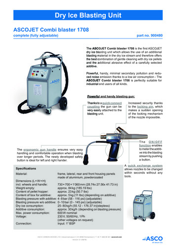
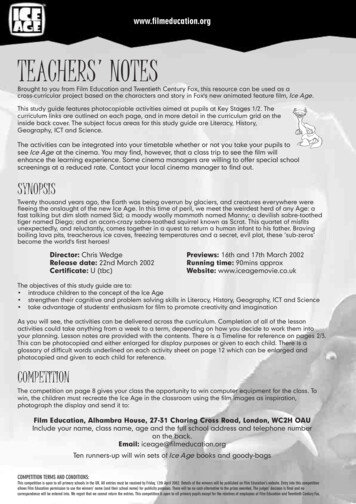
E-CO2 150 DescriptionThe E-CO2 150 will be supplied as follows:yyyyAbrasive pot & fittingsBlast hose2 bags 50 lb (22.7 kg) medium grade abrasive mediaChoice of one abrasive blast nozzleBACKFRONTExhaust Air Valveand MufflerAir Supply to TankValveAbrasive/No AbrasiveSelector SwitchTrigger CircuitConnectionsFilter Separator withManual DrainPot Pressure RegulatorTrigger Circuit RegulatorBlast Hose ConnectionMetering ValveAir/Dry Ice Supply fromDry Ice BlasterFigure 1: E-CO2 150 Unit10
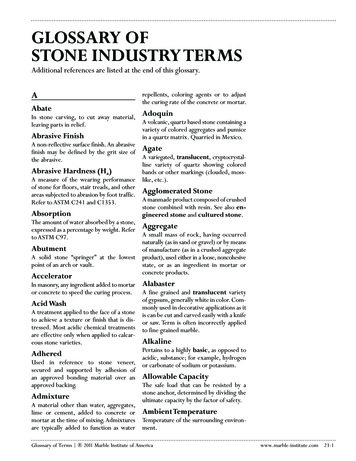
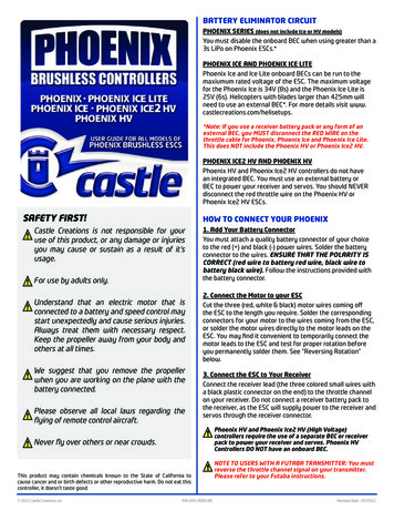
E-CO2 150 Recommended ComponentsFigure 2: E-CO2 150 /Aero2 PLT 60 OverviewFigure 3: E-CO2 150 Operator with proper PPE11
E-CO2 150 NozzlesNozzleNozzle Part No4E02914E02904E02954E0294Nozzle Specifications#7 - 7/16 in x 8 1/2 in (1.1 cm x 21.6 cm)255 cfm (7.2 m³/m) @100 psi#6 - 3/8 in x 7 3/8 in (.9 cm x 18.7 cm)200 cfm (5.7 m³/m) @100 psi#5 - 5/16 in x 6 1/4 in (.8 cm x 15.9 cm)140 cfm (4 m³/m) @100 psi#4 - 1/4 in x 6 in (.6 cm x 15.2 cm)80 cfm (2.3 m³/m) @100 psi12
OperationsWARNINGOnly trained and/or certified personnel should operate this system.Unpacking the E-CO2 150 SystemThe E-CO2 150 has been assembled and tested as one unit prior to shipment. Follow the steps below toinspect and unpack the system from the shipping container.1. Examine the shipping container for any damages that may have occurred during transport.2. Remove the E-CO2 150.3. Examine the system for any external damage that may have occurred during transport.4. Check for foreign materials that may have fallen inside the E-CO2 150 during shipment orpacking.Refer to the packing slip for a list of the components shipped with the E-CO2 150. Contact Cold Jet if anydamage has occurred to the shipping container or the E-CO2 150 (see “Contact Information” on page42).WARNINGNEVER perform any maintenance or attempt to open the E-CO2 150 in any waywhile it is pressurized. The violent release of compressed air and propelledobjects will cause serious injury or death.WARNINGOnly trained and/or certified personnel should operate the E-CO2 150 system.Personal Protective Equipment (PPE)WARNINGDo not operate the E-CO2 150 without proper PPE.Prior to operating the E-CO2 150, or loading dry ice into the Dry Ice Blaster, proper PPE must be used. Itis recommended that each operator is trained on the proper use of PPE.Wear protective glovesWear hearing protectionWear eye protectionRead operator and maintenance manual along with MSDS informationWear respirator as requiredWear full face shield13
Setting Up the E-CO2 150WARNINGImproper installation of hoses and adapters to the E-CO2 150 can cause damageto the machine.WARNINGDo not use the machine if any important parts of the machine are damaged, (e.g.safety devices, high pressure hoses, applicator).These instructions will apply to all three models of Cold Jet blasters. The illustrations may or may notcorrespond to the dry ice blasting machine you are using.It is recommended, for trouble free operation, that the compressed air be run through a Cold Jetaftercooler or an air dryer to remove as much moisture as possible from the blast air supply. Moistureis the enemy of both dry ice and abrasive media. It can cause icing up and abrasive clumping – bothleading to feeding and blasting problems.Connecting to the compressed air sourceWARNINGNEVER reach into the Pop-up opening while filling the E-CO2 150. It can closewithout warning causing severe injury or death.WARNINGNEVER use abrasives containing silica or beryllium.WARNINGNEVER fill the E-CO2 150 with the inlet valve in the open position. ALWAYS closethe valve before filling.WARNINGElectrically conductive media shall not be used with the E-CO2 150 using electricremote control systems without changing to sealed strain relief connectors.WARNINGNEVER attempt to transport the E-CO2 150 when it contains abrasive.WARNINGNEVER operate the E-CO2 150 without a remote control system.WARNINGUse only Cold Jet supplied remote control systems as others may start or stop theE-CO2 150 without warning.WARNINGNEVER reverse or make modifications to the remote control system.WARNINGALWAYS use caution around electric sources to avoid electric shock. Do notoperate electrical remote controlled E-CO2 150 systems in wet or hazardousenvironments.14
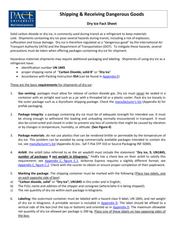
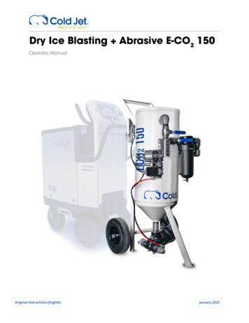
Compressed Air SupplyIt is important for proper operation of both, the dry ice blaster and the abrasive blaster, that theincoming air is connected properly. The abrasive media system has a pressure rating of 150 psi(10.3 bar). It is therefore necessary that the blast pressure of the dry ice blaster be set no higherthan 135 psi (9.3 bar). If the dry ice blaster is not equipped with a pressure regulator then theincoming supply pressure must not exceed 140 psi (9.6 bar). There are two 150 psi (10.3 bar) safetypressure relief valves that will pop if these pressures are exceeded.Figure 4 shows the connector that goes between the compressed air source and the dry ice blaster.It will come supplied connected to the abrasive system with the small hose. The threaded end willattach to the inlet of the dry ice blaster and the swivel end will attach to the supply hose. The whipcheck should slip over the supply hose. It may be possible that your hose or dry ice blaster has adifferent fitting – if so, it will be up to you to supply the correct fitting(s).Figure 4: Compressed Air SplitterUsing Plant Air (Central Compressed Air System)Manufacturing plants, with central compressed air systems, should have an After Cooler anda 2-stage coalescing filter assembly downstream of the receiver tank. Hot metal pipes are anindication this is needed.To verify that the plant air system is adequate for the blaster and the Aero E-CO2 150 the aircompressor needs to produce an air volume 10% greater than the blast machine’s maximum airvolume in addition to the air volume consumed by normal plant operation.To determine adequate air volume, watch the pressure gauge or digital pressure display while blasting.yIf the gauge drops slowly the compressor is insufficient.yIf the gauge drops quickly there is a restriction or the pipe is too small.yIf the gauge stays steady then the compressor and piping are adequate.15
To maintain adequate pressure to the blaster:yFrom the air compressor to 50 ft (15 m) use a flexible 1 in (2.5 cm) air hose (preferably thehoses supplied with the system).yFrom the air compressor to beyond 50 ft (15 m) make sure the pipe is 1 in (2.5 cm) indiameter before attaching the air hose.Water and rust will collect in the line. Before plugging into the air supply, purge the line, to preventcontamination of the CO2 or abrasive media.Using Portable Air (minimum of 185 cfm (5.6 m3/m))Portable diesel air compressors are frequently not optimized for dry ice blasting units and aretherefore not able to cool or remove air moisture.The Cold Jet After Cooler is required to reduce the discharge air temperature 180 F (82 C) to within15 F (-9 C) of ambient air temperature. Visit coldjet.com to learn more about purchasing a Cold JetAfter Cooler.Without the After Cooler, the following may occur:1.2.3.4.5.Incoming air moisture may rapidly cool and freeze at the blaster feeder.Water ice may accumulate in the feeder, distorting the air flow and seal.Water ice buildup may continue inside the blast hose, to the nozzle.Media may clump.Water ice may break off inside the hose and lodge in the nozzle, causing a jam.6. Water ice, may exit the nozzle, and damage the target surface.If blasting continuously, an air dryer will further reduce the air moisture (dew point). Desiccantdryers produce a dew point of -40 F (-40 C), resulting in a dew point low enough for continuousblasting.To verify the compressor is of adequate size for the system, the air compressor needs to produce anair volume 10% greater than the blast system’s maximum required air volume.To determine adequate air volume, watch the pressure gauge or digital pressure display whileblasting.yyyIf the gauge drops slowly the compressor is insufficient.If the gauge drops quickly there is a restriction or the pipe is too small.If the gauge stays steady then the compressor is adequate.To maintain adequate pressure, the hose size from the compressor to the blast system needs to be1 in (2.5 cm) in diameter.16
Connecting the E-CO2 150 to the Dry Ice BlasterBefore connecting any hoses to the E-CO2 150, ensure that the inlet valve is closed and thecompressed air supply is off.WARNINGALWAYS use safety devices like slips and whip checks (safety cables) at hoseconnections.Before pressurizing the E-CO2 150, ensure the following occurs:yyyyyyyyAll procedures have been followedThe inlet valve is closedThe blow down valve is closedThe remote control handle is releasedAll hose connections are secured with safety devices in placeThe E-CO2 150 is set up in a safe and level location where all people in the vicinity are awareof its locationAll necessary safety equipment is present and being worn by all people in the vicinity of theE-CO2 150Only personnel who have been thoroughly trained and have read and understand the DryIce Blaster operator manual are in the vicinity of the E-CO2 150Once the blaster is properly set up for operation, turn on the air and use the procedures in theblaster operator manual to start the machine.The next step is to connect the dry ice blaster to the Abrasive Blaster. Using the supplied 1 in (2.5cm) hose connect one end to the inlet of the abrasive system and the other end to the outlet of thedry ice machine. If the dry ice blaster is an Aero2 PLT 60 you will need to use the quick disconnectadapter supplied. (figure 6).Next, the trigger connector must be attached. The connector you have will depend upon which dryice blaster you have. The connector will already be attached to the E-CO2150.17
PLT 60 connections:When connecting the air supply hose to the blaster, always run the hose through the choker of thewhip check in case of accidental disconnect.Figure 5: Whip CheckAero2 PLT 60 Connections:Figure 6: Aero2 PLT 60 Connections18
Aero C100 Connections:Figure 7: Aero C100 ConnectionsAero 80FP Connections:Figure 8: Aero 80FP Connections19
Attaching the Blast Hose to the E-CO2 150There are three connections to be made when attaching the blast hose. The large blast hose andtwo small signal hoses with quick connect fittings. The large hose has a twist claw type fitting. Lineup the ‘feet’ with the cut outs and twist – making sure the anti-rotation pin locks in place. This isimportant to ensure the hose does not come separated during use. The quick connect fittings cannow be connected at the control plate. (figure 9) Lastly the washer can be inserted and the nozzlecan be screwed into the nozzle adapter at end of the blast hose.Blast Hose ConnectionFigure 9: Blast Hose ConnectionWhen connecting the blast hose to the metering valve, rotate the hose fitting clockwise until thesafety pin locks into place. Be sure thet the safety pin is locked by trying to twist the fitting counterclockwise to remove. The fitting should remain in place. To remove the blast hose lift the safety pinand rotate counter-clockwise.Metering ValveMixed MediaBlast HoseFigure 10: Safety PinSafety Pin20
Safety PinFigure 11: Attaching the Blast HoseDry Ice OnlyAbrasiveDry IceFigure 12: Signal Hose ConnectionsConnect the small signal hoses into the control side of the Abrasive Blaster. There is only one waythey will connect.21
Figure 13: Nozzle AssemblyWhen installing the nozzle, be sure the nozzle seal is small side down/toward the blast hose asillustrated in figure 13 and not toward the nozzle or the nozzle connection may leak around the seal.In order to activate the trigger to the nozzle, the safety button must be depressed.TriggerSafety ButtonFigure 14: Trigger and Safety Button22
OperationWARNINGNEVER exceed 150 psi (10.3 bar) operating air pressure.WARNINGNEVER perform any maintenance or attempt to open the E-CO2 150 inany way while it is pressurized. The violent release of compressed air andpropelled objects will cause serious injury or death.WARNINGOnly trained and/or certified personnel should operate or rig the E-CO2 150system for shipment or movement.WARNINGThe blast hose may kick back once the trigger is depressed. Be prepared andbrace yourself for kick back. The E-CO2 150, due to the metering valve, willnormally kick back erratically for a short time when started.WARNINGAirborne particles produced by abrasive blasting can cause respiratorydisease. All persons operating or located near the blasting site must wearNIOSH / OSHA approved breathing equipment. NEVER use abrasivescontaining silica.WARNINGNEVER stand near a E-CO2 150 while it is in operation. The release of theremote control handle will cause a sudden and violent release of compressedair from the exhaust hose without warning. Only adjust the metering valveafter the E-CO2 150 has been depressurized.WARNINGOnly personnel thoroughly trained in abrasive blasting should operate theE-CO2 150. This manual only provides the basic information on how to safelyoperate the features of the Cold Jet series E-CO2 150.This manual only covers the E-CO2150 of the Dry Ice Blasting Abrasive System. For any informationon the dry ice blaster refer to that machines manual.The emergency stop for the Dry Ice Blaster will also shut down the E-CO2 150Make sure the air compressor is on and the supply air shut off valve is open. Make sure the Dry IceBlaster is plugged in and powered up.If using the Cold Jet Aero2 PLT 60 Dry Ice Blaster, make sure the button is depressed on the TriggerConnector – it will light up blue. (figure 15)23
Figure 15: Aero2 PLT 60 Trigger Connector ButtonBlasting Dry Ice OnlyWARNINGNEVER point the blast nozzle at yourself, other people, or equipment that isnot intended to be blas
This system uses dry ice (CO 2 in solid form). The temperature of dry ice is -109 F (-78.9 C). Avoid coming into direct contact with dry ice as it may cause severe tissue damage. Study the material safety data sheet (MSDS) of dry ice (CO 2) supplied with the delivery of dry ice and follow all the recommendations and guidelines listed therein.