Transcription
PLANNING AHEADLIGHTING12
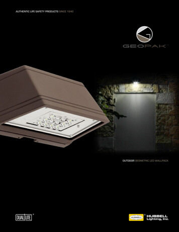
Trex Outdoor Lighting LIGHTING & DESCRIPTIONITEM NUMBERDECK LIGHTINGPyramid or Flat Post Cap Light» 4" x 4" LED Post Cap Light[4.55 in x 4.55 in (115 mm x 115 mm)actual internal dimensions]Use with Trex 4 in Composite Railing Posts» 5.5 ft (1.67 m) Male LightHub LeadAluminum Post Cap LightPYRAMID 4C» 2.5" x 2.5" LED Aluminum Post Cap Light[2.6 in x 2.6 in (66 mm x 66 mm) actual internal dimensions]Use with Trex 2.5 in Aluminum Railing Posts» 5.5 ft (1.67 m) Male LightHub LeadDeck Rail Light» LED Deck Rail Light[2.75 in (69 mm) OD]FLAT 4CTEXTURED CHARCOAL BLACK:BKALCAPLED25TEXTURED BRONZE: BZALCAPLED25TEXTURED WHITE: WTALCAPLED25TEXTURED CHARCOAL BLACK: BKLAMPLEDCTEXTURED BRONZE: BZLAMPLEDCTEXTURED CLASSIC WHITE: WTLAMPLEDC» 5.5 ft (1.67 m) Male LightHub LeadWedge Deck Rail Light» LED Wedge Deck Rail Light[1.875 in wide x 3 in high (47 mm x 76 mm) actual dimensions]Compatible with all Trex Railing PostsTEXTURED CHARCOAL BLACK: BKALPOSTLAMPLEDTEXTURED BRONZE: BZALPOSTLAMPLEDTEXTURED CLASSIC WHITE: WTALPOSTLAMPLED» 5.5 ft (1.67 m) Male LightHub Lead» 4 LED Riser Lights[1.25 in (31 mm) OD]TEXTURED CHARCOAL BLACK: BKRISERLED4PKCTEXTURED BRONZE: BZRISERLED4PKCTEXTURED CLASSIC WHITE: WTRISERLED4PKC» 5.5 ft (1.67 m) Male LightHub LeadRecessed Deck LightsRECESSLED4PKCLIGHTINGLED Riser Lights» 4 LED Recessed Lights[1 in (25 mm) OD]» 5.5 ft (1.67 m) Male LightHub LeadACCESSORIESTransformer with Timer»»»»»Output Voltage: 12VDCOutput Power: 100W or 30WOutput Current: 8.3A or 2.5APhoto-Activated Timer20 ft (6.09 m) LightHub Wire Extension CableMulti-zone Transformer Adapter8.3A, 100W: DIMMABLE 83DLTRANSFORMERCC2.5A, 30W: 25DLTRANSFORMERDL5TFSPLIT1PKMotion Controller And Dimmer» 1 Remote» 1 Motion Sensor» 2 AAA Batteries» 2 Screws» 5 ft. Male/Male Wire Extension CableDimmer» Single Channel with Remote1 in (25 mm) Forstner Bit—Pack of 6BKDLMOTIONWTDLMOTIONDLDIMMERDLBIT6PKLightHub Accessories»»»»»»»»3-Way Splitter6-Way Splitter5 ft (1.52 m) Wire Extension Cable10 ft (3.04 m) Wire Extension Cable20 ft (6.09 m) Wire Extension Cable40 ft (12.19 m) Wire Extension Cable60 ft (18.28 m) Wire Extension CableFemale to Female DL20FTWR4PKDL40FTWR2PKDL60FTWR1PKDLFADAP6PK13
HOW TO INSTALL TREX DECKLIGHTINGPARTSAAPyramid Post Cap LightBCFlat Post Cap LightDEx2Deck Rail LightRiser LightRecessed Deck LightSplitterADBECNOTE: All wiring and splitters are mounted to the insideof framing. Picture above is a general representation ofwhere to place them.TOOLS NEEDED1/2"(13 mm)NOTE: It is recommended to install wiring and splittersCD and railing have been installed. DO NOTbeforedeckingrun wires between joists and deck boards.x2x2x2HELPFUL TIPSLighting and Wiring OverviewLIGHTINGNOTE: Avoid railing brackets and locations for deck raillights when running wires up posts.x2» 5ft, 10ft, 20ft, 40ft, and 60ft connection/extensionBwires sold separately (these are male-to-maleconnection wires).x214WARNING:» DO NOT INSTALL DECKLIGHTING IN CLOSEPROXIMITY TO POOLS OR HOT TUBSAS CHEMICALS FROM THE WATER CANDAMAGE LIGHTING FIXTURES.» DO NOT INSTALL WIRING UNDER HEAVYWEIGHT OR LOAD AS THIS CAN DAMAGEWIRING.1"(25 mm)» Please note that Trex lighting operates on DCpower. NEVER mix AC and DC fixtures on thesame circuit. Doing so will result in extremelypremature fixture failure and is not covered bythe Trex limited warranty. You must use a Trextransformer on all Trex lighting installations.» Never fully drive staples when securing wire.Wire should move under staple.» ALWAYS protect any wire that is close to theground with conduit or wire loom to preventrodent damage.» Cap all unused female connections with capsprovided or weather-resistant silicone to preventwater damage or corrosion.» Each dimmer operates on a separate remote.» It is recommended to have power sourceinstalled and turned on when installing lights toensure all components work.» When installing wiring, avoid extreme angles,pressure, or tension on the wiring, as this cancause pinching of the wiring and create a lightingfailure.NOTE: Construction methods are always improving. Please refer to www.trex.com for the most up-to-date installation requirements.
HOW TO INSTALL TREX DECKLIGHTING/CONTINUEDGeneral Information» R efer to www.trex.com for instructional videos onhow to install Trex DeckLighting.» USE TREX TRANSFORMER ONLY. Use of any othertransformer voids warranty.32TRANSFORMER CAPACITY BY TYPEType ofLight8.3A Transformer(83 DL TRANSFORMER)6"(152 mm)2.5A Transformer(2.5 DL TRANSFORMER)Riser28590Recessed28590Post Cap8522Deck Rail28590Above listing is for maximum number of each individual types of lights.If mixing and matching lighting, contact Trex to determine if more thanone transformer is required.PlanningTo SplitterGFCI1. The dimmer remote will work Outletin a 30' (9 m) radius of the unit.2. Dimmer should be installed inDimmera dry location.Timer(Optional)3. Timer must be installedvertically with receptaclefacing downwards. Timer mustbe at least 1' (.305 m) fromTransformerground level when installedas per federal safety code height regulations. Timermust be in view of the sun to use the dusk/dawnfeature.Installing WiringNOTES:» It is recommended to install wiring and splittersbefore decking and railing have been installed.» Use male-to-male connection wire (lengths vary)that will connect to eachrequired splitter.11. Wiring must be run underdecking structure andbehind stringers. DO NOTrun wires between deckboards and joists. Stapleto frame with cable staplesat least 1/4" (6 mm) wide.DO NOT crush wire insulation with staples.Making Connections1. Install splitters toinside of framing usinghardware provided.Install at every postbase where lighting ispresent and dependingon spacing in betweeneach riser and recessedlight.11232LightconnectionLIGHTING OTE: When designing your deck, plan locations ofNlights, power supply, timer, and dimmer. These shouldbe accessible for service. Installing a GFCI outlet isREQUIRED to help prevent damage to lighting fromelectrical surges.2. Wiring can be run under deck and behind risers.Staple to frame with cable staples at least 1/4"(6 mm) wide. DO NOT crush wire insulation withstaples.3. Remove 5' (1.52 m) lead wire that is connectedto post cap and attach wire to post with maleconnection at top of post (female connection wouldbe at bottom of post and connect into splitter). Avoidrunning wire on side of post where railing brackets ordeck rail lights will be installed. Leave approximately6" (152 mm) of lead at top to make connections.Staple to frame and posts with cable staples at least1/4" (6 mm) wide.DO NOT crush wire insulation with staples.ConnectionwireConnection wire2. Attach male lead from lights to female connectionson splitter. Also attach male-to-male connectionwires in between each splitter. Continue until allwiring from lights are attached to splitters andconnector wires are attached in between splitters.3. Cap off all unused female connections on splittersusing caps provided or weather-resistant silicone.15
HOW TO INSTALL TREX DECKLIGHTING/CONTINUEDTimer Operation Instructions321. Select the mode of operation:» Dusk to Dawn» 2–8 hours» Always “ON”» “OFF”PostPostSleeveProgram repeats daily. When power is flowing to lights,green light above POWER is on.Installing Post Cap LightsNOTE: Install post cap lights after the railing system, postsleeve skirt, and post sleeve have been installed.122. Drill a 1" (25 mm) hole through post sleeve. Drill deepenough to mark location on pressure-treated post.3. Remove the post sleeve from the post.5416"(152 mm)2213LIGHTING1231. Connect male lead from wiring to female connectorfrom cap. Also attach male-to-male connection wiresin between each splitter. Continue until all wiringfrom lights is attached to splitters and connectorwires are attached in between splitters.(See Making Connections section for details.)2. After verifying wiring is correct by turning lights on,attach cap to top of post with silicone caulk.4. Drill out existing hole on pressure-treated post3/4" (19 mm) deep. Drill two additional holesvertically below main hole—this will allow space forwiring after post sleeve is attached.5. Leave enough slack at top of lead wire and attachlead wire to post using staples. Attach lead wire tosplitter under decking.TIP: To hold lead wire in place at drilled-out location,Installing Deck Rail Lightsuse painters tape.NOTE: Instructions shown below are for new deckinstallation and are shown BEFORE railing system hasbeen installed.1. Place post sleeve overpressure-treated postand mark desiredheight, centered on postsleeve for deck rail lightlocation.7221NOTE: If deck boards arenot installed yet, place adeck board on framing toensure post sleeve is at correct height.166116. Slide post sleeve back over post. If using a postsleeve skirt, make sure to install the skirt first.Connect plug on deck rail light to lead wire and tuckwiring into previously drilled-out pockets on post.7. Align holes for screws horizontally and attach fixturebase to post with provided screws.NOTE: Construction methods are always improving. Please refer to www.trex.com for the most up-to-date installation requirements.
HOW TO INSTALL TREX DECKLIGHTING/CONTINUED8. Line up polycarbonatelens with fixture housing.Twist onto fixture base.Continue until all wiringfrom lights is attached tosplitters and connectorwires are attached inbetween splitters.(See Making Connectionssection for details.)8Continue until all wiring from lights is attachedto splitters and connector wires are attached inbetween splitters.(See Making Connections section for details.)12NOTE: DO NOT install riser light or deck rail light into topor bottom rails or balusters.Installing Recessed Deck LightsNOTE: Install recessed deck lights after installingdecking.NOTE: If railing has already been installed, lead wires willneed to be fished through the post sleeve to reach thedesired location for the deck rail light. In some cases, ifthe provided lead wire does not fit (due to connectorsize), the wire connectors can be cut off and wire nutscan be used. Test lights with the power on. If lights thatare wired with this method do not function, then switchthe connector wires.1. Mark locations forlights in deck boards.1NOTE: If possible, avoidlocations over joistsas holes will be moredifficult to create.NOTE: Install riser lights after stairs and risers havebeen installed.1. Mark locations foreach light, generally4" (102 mm) above tread.Consult local codes forlighting requirements.14"(102 mm)NOTE: If possible, avoidlocations over stringersas holes will be moredifficult to create.23122. Drill a 1" (25 mm) diameter hole at least 1" (25 mm)deep into riser. If riser material is thicker than1" (25 mm), use a 1/2" (13 mm) drill bit to create apassage for wires.3. Thread wires through hole. Press light into hole,ensuring lens is horizontal. Make connections behindstairs from male lead wire from recessed light intofemale connection on splitter. Also attach maleto-male connection wires in between each splitter.2. Drill a 1" (25 mm)2diameter hole13/4" (19 mm) deepinto deck board. Holecannot go all the waythrough deckboard orlight will fall through.2Make sure drill bit isperpendicular to board. 3/4" (19 mm)Drill a 1/2" (13 mm)diameter hole in base of the first hole through deckboard.LIGHTINGInstalling Riser Lights3. Thread wires through32hole. DO NOT pull LEDinto hole by pullingon wires. This maydamage wires or LED.Press light into hole1until flush with surface.Make connections underdeck from male leadwire from riser light intofemale connection on splitter. Also attach maleto-male connection wires in between each splitter.Continue until all wiring from lights is attachedto splitters and connector wires are attached inbetween splitters. (See Making Connections sectionfor details.)17
HOW TO PROGRAM DIMMER REMOTEA. ALWAYS keep antennafully extended formaximum range.3B. Up/Down arrowsgradually dim or brightenlighting.AC. On/Off button cycleslights ON/OFF.D. M ode button cyclesthrough 3 presetdimming levels: High,Medium, Low, and Off.BCLIGHTINGD3. Press and hold both the up and down arrow on thedimmer remote simultaneously.4NOTE: First, make sure thered light is illuminated onthe remote. If there is nored light and the product isnew, contact 1-800 BUYTREX for a replacement. Ifthe product is not new, theA27 battery is replaceable.21. Install dimmer perinstructions and makesure lights are ON andworking properly.2. Unplug the transformerto turn lights OFF.124. With the dimmer arrow buttons held down, plug thetransformer back in. The lights should blink once toconfirm programming.5. Release the up and down arrows on the remote andtest remote to confirm proper operation.HOW TO INSTALL TREX SIGNATURE CAP LIGHT(CAN ONLY BE USED ON TREX SIGNATURE POSTS)PARTSTOOLS NEEDEDAPost Cap Light(includes 5ft male-to-male wire)9/16" x 6" or Longer(14 mm x 152 mm)» 5ft, 10ft, 20ft, 40ft, and 60ft connection/extensionwires sold separately (these are male-to-maleconnection wires).18NOTE: Construction methods are always improving. Please refer to www.trex.com for the most up-to-date installation requirements.
HOW TO INSTALL TREX SIGNATURE CAP LIGHT/CONTINUED(CAN ONLY BE USED ON TREX SIGNATURE POSTS)3HELPFUL TIPS3. Using a 9/16" (14 mm) x 6" (152 mm [or longer]) drillbit, drill a diagonal hole through the decking andblocking. Ensure that the angle will allow wire to notbe pinched by support plate under blocking (if usingTrex ALPOSTHWDECK mounting kit). (See MakingConnections section for details.)4. Turn post upside down and fish 5' male-to-male wire(provided) through hole in baseplate.5611Installing Post Cap Lights2NOTE: Instructions shown below are for new deck installation and are shown BEFORE railing system has beeninstalled.1LIGHTING» Leave slack in wire to make fixture terminations.» Post lamps work well at changes in levels of adeck—at the top or the bottom of the stairs, or inconjunction with post cap lights.» Splitters should be used at each post that haslights and depending on spacing in betweeneach riser and recessed light.» Cap all unused female connections with capsprovided or weather-resistant silicone to preventwater damage or corrosion.» The splitter is cross-linked so there is nospecified plug for lights versus lead wires.» Leads attached to each light are approx.5.5' (1.67 m) in length and have male terminalsto plug into splitter.» Use a separate dimmer control for each lighttype for maximum control.» It is recommended to have power source onwhen installing lights to ensure all componentswork.425. Connect the female connector on the post cap lightto this wire and, using a rubber mallet, gently tap thecap onto top of post until it is secure.6. Turn post over and carefully fish wire through holecreated in Step 3 to underside of the deck. Ensureexit point of wire under blocking will not be pinchedby ALPOSTHWDECK plate.7. Mount post per instructions.5' Male-to-Male Wire(from Post Cap)1. Before attaching post to deck, locate placement ofpost and mark desired bolt locations.2. Using a straight edge, mark an “X" between the fourbolt locations.3-Way Splitter5' Male-to-Male Wire(from Baseplate hole)5' Male-to-Male Wire(from Post Lamp)NOTE: If connecting a Trex Wedge Deck Rail Light aswell, a 3-way adapter and extra 5' male-to-male wire(not provided) can be used inside the post so that onlyone wire must be run through the hole in the base of thepost (and post blocking). This is optional.19
HOW TO INSTALL TREX WEDGE DECK RAIL LIGHT(CAN ONLY BE USED ON TREX SIGNATURE POSTS)Installing Post LampsPARTSNOTE: Instructions shown below are for new deckinstallation and are shown BEFORE railing system hasbeen installed.Ax31Wedge Deck Rail Light(includes 5ft male-to-male wire)2» 5ft, 10ft, 20ft, 40ft, and 60ft connection/extensionwires sold separately (these are male-to-maleconnection wires).TOOLS NEEDEDLIGHTING9/16" x 6" or Longer(14 mm x 152 mm)34HELPFUL TIPS» Leave slack in wire to make fixture terminations.» Deck rail lights work well at changes in levels of adeck—at the top or the bottom of the stairs, or inconjunction with post cap lights.» Splitters should be used at each post that haslights and depending on spacing in betweeneach riser and recessed light.» Cap all unused female connections with capsprovided or weather-resistant silicone to preventwater damage or corrosion.» The splitter is cross-linked so there is nospecified plug for lights versus lead wires.» Leads attached to each light are approx.5.5' (1.67 m) in length and have male terminalsto plug into splitter.» Use a separate dimmer control for each lighttype for maximum control.» It is recommended to have power source onwhen installing lights to ensure all componentswork.201. Before attaching post to deck, locate placement ofpost and mark desired bolt locations.2. Using a straight edge, mark an “X" between the fourbolt locations.3. Using a 9/16" (14 mm) x 6" (152 mm [or longer]) drillbit, drill a diagonal hole through the decking andblocking. Ensure that the angle will allow wire to notbe pinched by support plate under blocking (if usingTrex ALPOSTHWDECK mounting kit).4. Locate placement of post lamp. Mark entry point ofthe wire.5. Drill 9/16" (14 mm) hole5where wire will enterpost.NOTE: Construction methods are always improving. Please refer to www.trex.com for the most up-to-date installation requirements.
HOW TO INSTALL TREX WEDGE DECK RAIL LIGHT(CAN ONLY BE USED ON TREX SIGNATURE POSTS)6107a113216. Turn post upside down and fish 5' male-to-male wire(provided) through hole in baseplate.7a. If connecting a Wedge Deck Rail Light only, pull wirethrough hole.TIP: Insert a zip-tie loop (or small grabber tool)through 9/16" (14 mm) hole. Fish wire throughloop in zip-tie. Pull wire through hole with zip-tie.85' Male-to-Male Wire(from Post Cap)7b3-Way Splitter5' Male-to-Male Wire(from Baseplate hole)921LIGHTING7b. I f connecting a Trex Signature post caplight as well, and usingthe 3-way splitter (seenote after Step 12),simply run one wirethrough the holecreated in Step 5to the top of the post.10. .Slide light cover down over backing plate, adjusting.mounting screws as necessary to achieve a tight fit.11. Turn post over and carefully fish wire through holecreated in Step 3 to underside of the deck. Ensureexit point of wire under blocking will not be pinchedby ALPOSTHWDECK plate.12. Mount post per instructions.5' Male-to-Male Wire(from Post Lamp)NOTE: If connecting a Trex Signature post cap lightas well, a 3-way adapter and extra 5' male-to-male wire(not provided) can be used inside the post so that onlyone wire must be run through the hole in the base of thepost (and post blocking). This is optional.8. Connect male connector to female connector onlight housing.9. Place light and attach backing plate to post withthree screws (provided).21
HOW TO INSTALL TREX PHOTOCELL MOTION CONTROLLERTREX PHOTOCELL MOTION CONTROLLERSENSOR OVERVIEWPARTSBAx2CDInput(to transformer)Red TabMotionSensorEDay/LightSensorSensorIndicator5' Male-to-Male WireTOOLS NEEDEDLIGHTINGOutput(to lights)TREX PHOTOCELL MOTION CONTROLLERSENSOR INSTALLATION LOCATION1/2"(1.27 cm)1"(2.5 cm)TREX PHOTOCELL MOTION CONTROLLEROVERVIEWInstall the Motion Controller in a location that is exposedto some ambient sunlight. If you plan to use the motionsensor capabilities of this unit, place it in a location thatallows the center of the unit to face the location of themotion. For example, the door leading onto the deck,or at the bottom or top of stairs are common locations.However, the most important consideration of MotionController location is how you will install it into yourlighting circuit. See illustrations on next page for somebasic examples.Indicator BacklightProgrammingResetDimmingTimeZone22NOTE: Construction methods are always improving. Please refer to www.trex.com for the most up-to-date installation requirements.
HOW TO INSTALL TREX PHOTOCELL MOTION CONTROLLER/CONTINUEDMaking A Post Pocket2112324PostPostSleeve1Aluminum Post InstallOne Sensor Install1A110 VAC OutletInput fromTransformerEOutput VDC OutputLIGHTING1SensorTransformer(Not Included)Note: Make sure the sensor is installed after the transformer, but beforethe first light. Any lights that are installed before the sensor will not becontrolled.Two Sensor Install110 VAC OutletInput htLightLightLightOuput tolights12VDCInput from 3-Way SplitterOuput tolights3-WaySplitterTransformer(Not Included)SensorSensorTo install two sensors, place a motion sensor at each end of the circuit, making sure you connect thewire with the red tab to the transformer side of each circuit.23
HOW TO INSTALL TREX PHOTOCELL MOTION CONTROLLER/CONTINUEDTo install multiple circuits, use the 5-Way TransformerSplitter and (1) additional 20’ Transformer wire(available on shoptrex.com) for each circuit you’resetting up. Then simply follow the instructions for theone-sensor installation above.Step 4Press Program button once to save. Press Programbutton again to exit programming mode.Tip: The motion sensor will not activate the lights if thephotocell senses daylight.Multiple Zone InstallTo run multiple zones, you simply create multiple onesensor circuits. For example, we recommend runningyour recessed lights on one dimmer circuit and yourpost lamps, post lights and riser lights on another.Once installed, you can program each sensor for theappropriate motion sensitivity and light output for thatcircuit. Ensure that all sensors are on the same timesetting if you want all of the lights to come on/go offat the same time.Adjustment of the photocell is usually not necessary. (Itis factory pre-set to 3.) However, if you place the receiverin an area that gets very little ambient light, you mightneed to turn the sensitivity up for it to function properly.Alternatively, if you want to use the receiver as a motioncontroller-activated device only, you may set the photocellsensitivity to 0. In that setting, the only time your lights willilluminate is when the motion sensor is activated.Step 1ADJUSTMENTSLIGHTINGPhotocell SensorInstall and mount controller per instructions above.Plug in lights.Motion SensorThe motion sensor is set to maximum range at the factory.If you want to prevent the motion sensor from controllingthe lights, adjust it to the lowest setting.Step 1Install and mount controllerper previous instructions.Plug in lights.Step 2Press and hold Programbutton on the remote for4 seconds. The blue light onthe receiver will light up solid.Step 3Step 2Press the Day/Light button on theremote. The receiver will blink once.Enter a number on the keypad 0-9.Press and hold Program button on the remote for4 seconds. The blue lighton the motion controllerwill light up solid.1 C omplete darkness required to activate photocell.9 Photocell operates in full sunlight.0 Photocell will no longer control lighting system.Step 3Use the /- buttons to adjust the sensitivity of themotion sensor. There are 9 steps between maximumrange and minimum range. The indicator light will blinktwice when either limit is reached. The lowest limit willdeactivate the motion sensor.x1TIP: The motion controller senses heat. Therefore,ambient temperatures can affect sensitivity. The coolerthe ambient temperature the greater the detectionrange. Max Setting 25 feet at 72 F.x2Step 4Press Program button once to save.Press Program button again to exitprogramming mode.x1x1x1x2x2x2x124x2NOTE: Construction methods are always improving. Please refer to www.trex.com for the most up-to-date installation requirements.
HOW TO INSTALL TREX PHOTOCELL MOTION CONTROLLER/CONTINUEDADJUSTMENTS/CONTINUEDOTHER BUTTONS/FUNCTIONS/ZONESTime DurationBacklightAdjustment of the timer controls how long the lights stayon once activated by the photocell or motion sensor.Press the Backlight button toilluminate the remote in low lightconditions.Step 1Install and mount controller per instructions above. Plug inlights.Hashtag (Reset)x2x2Step 1Press and hold thehashtag button for6 seconds until thereceiver indicator lightblinks twice.Step 2Press and hold Programbutton on the remote for4 seconds. The blue lighton the receiver will lightup solid.x1x2x2x2LIGHTINGx1TIP: When installing multiple motioncontrollers on the same circuit theyboth must be set to the same time x1duration.x2Step 2Press the On/Off button to turnthe system off, then press the On/Off button again to complete thefactory setting reset process.Step 3Press the Timer button, then enter thedesired number of minutes desired(1-999).Step 4Press Program button once tosave. Press Program button againto exit programming mode.x2x2ZoneAssign/select zones for each receiver.Step 1To assign or changezone press and hold theProgram button untilreceiver indicator lights up.Step 2Press Zone button; enter zonenumber (1-9).Step 3Press Program button once tosave. Press Program again to exitprogramming.x1x1x1x1x1 x2x2x1x2x2x2x225
LIGHTING Pyramid or Flat Post Cap Light » 4" x 4" LED Post Cap Lig ht [4.55 in x 4.55 in (115 mm x 115 mm) actual internal dimensions] Use with Trex 4 in Composite Railing Posts » 5.5 ft (1.6 7 m) Male LightHub Lead Aluminum Post Cap Light » 2.5" x 2.5" LEDAluminum Post Cap Lig ht [2.