Transcription
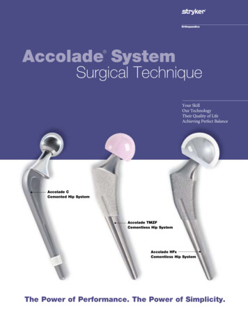
Step 2Accolade SystemSurgical Approach and ExposurePatient Position: Lateral Surgical TechniquePosterolateral Exposure: Skin incision isa gentle curve centered over the greater trochanter (Figure 2A). The ilio-tibial band is incised in line with the incision and the gluteus maximusmuscle is split proximally. The tendon of the gluteus maximus is detached from its insertion on the femur at the distal portion of the woundpartially or completely depending on the presence of external rotation contracture. A trapezoidal posterior myocapsular flap, consisting of thepiriformis and part of the gluteus minimus, the short external rotators and quadratus (Figure 2B), is developed and detached from the femurto expose the proximal posterior portion of the femur.Your SkillOur TechnologyTheir Quality of LifeAchieving Perfect Balance2A2BStep 3 Accolade CCemented Hip SystemA Steinman Pin is inserted into the infra-cotyloid groove of the acetabulum and held vertically against the femur (Figure 3). A locator mark ismade on the posterior portion of the greater trochanter. The position of the limbs in slight adduction, flexion and external rotation is identifiedand recorded on the drapes.Limb Length MeasurementAccolade TMZFCementless Hip SystemAccolade HFxCementless Hip System3The Power of Performance. The Power of Simplicity.Locator mark c1
Accolade SystemFemoral Hip SystemAccolade C & Accolade HFxIndications:The indications for use of total hip replacement prostheses include: Noninflammatory degenerative joint disease including osteoarthritis and avascular necrosis; Rheumatoid arthritis; Correction of functional deformity; Revision procedures where other treatments or devices have failed; and, Treatment of nonunions, femoral neck and trochanteric fractures of the proximal femur with headinvolvement that are unmanageable using other techniques.Contraindications:Absolute contraindications include: overt infection; distant foci of infections (which may cause hematogenous spread to the implant site); rapid disease progression as manifested by joint destruction or bone absorption apparent onroentgenogram; skeletally immature patients; and, cases where there is a loss of abductor musculature, poor bone stock, or poor skin coverage around thehip joint which would make the procedure unjustifiable.Conditions presenting increased risk of failure include: uncooperative patient or patient with neurologic disorders, incapable of following instructions; osteoporosis; metabolic disorders which may impair bone formation; and, osteomalacia.Accolade TMZFIndications: Noninflammatory degenerative joint disease including osteoarthritis and avascular necrosis; Rheumatoid arthritis; Correction of functional deformity; Revision procedures where other treatments or devices have failed; and, Nonunions, femoral neck and trochanteric fractures of the proximal femur with head involvement thatare unmanageable using other techniques.Contraindications: Active infection or suspected latent infection in or about the hip joint; Bone stock that is inadequate for support or fixation of the prosthesis; Skeletal immaturity; Any mental or neuromuscular disorder that would create an unacceptable risk of prosthesis instability,prosthesis fixation failure, or complications in postoperative care; and Obesity. An overweight or obese patient can produce loads on the device that can lead to failure of thefixation of the device or to failure of the device itself.Warnings and Precautions:See package insert for warnings, precautions, adverse effects and other essential product information.Before using Accolade System instrumentation, verify: Instruments have been properly disassembled prior to cleaning and sterilization; Instruments have been properly assembled post-sterilization; Instruments have maintained design integrity; and, Proper size configurations are available.For cleaning and sterilization instructions of surgical instruments, refer to the instrument package insert.
Table of ContentsAccolade C Cemented Surgical Technique. 2Pre-operative Planning and X-Ray Evaluation. 2Surgical Approach and Exposure. 3Limb Length Measurement. 3Neck Length and Offset Measurement. 4Neck Resection. 5Box Chisel. 6Starter Reamer. 6Alignment Rod. 7Trochanteric Reamer. 7Broaching. 8Calcar Planing. 8Trial Reduction. 9Sizing of the Distal Canal. 11Cleaning the Canal and Cement‑Plug Insertion. 11Final Canal Preparation and Cement Delivery. 12Stem Preparation and Head Selection. 13Femoral Stem Insertion. 13Closure. 14Accolade TMZF and Accolade HFx Surgical Technique. 15Pre-operative Planning and X-Ray Evaluation. 15Neck Resection. 16Opening the Femoral Canal: Axial Starter Reamer. 17Rasping the Femur. 18Seating Levels. 18Trial Reduction. 20Femoral Stem Insertion. 21Femoral Stem Insertion Option. 22Head Assembly. 22Closure. 23Instrument Ordering Information. 24 Implant Ordering Information. 26Accolade C Cemented Hip SystemComponent Ordering Information. 26 Simplex P Bone Cement Ordering Information. 26 Accolade TMZF and Accolade HFx Cementless Hip SystemComponent Ordering Information.27This publication sets forth detailed recommended procedures for using Stryker Orthopaedics devices andinstruments. It offers guidance that you should heed, but, as with any such technical guide, each surgeonmust consider the particular needs of each patient and make appropriate adjustments when and as required.
Accolade C Cemented Surgical TechniqueObjectives1. To place the stem in neutral position in the medullary canal with an adequate cement mantle.2. To restore the offset, limb length and center of rotation.Step 1Pre-operative Planning and X-Ray EvaluationPre-operative planning allows:1. Appropriate implant size selection.2. Restoration of leg length, offset and center of rotation.3. Appreciation of anatomic anomalies of the femur.Method: A standing A/P pelvis radiograph is utilized. The center of the femoral heads and the axis of the medullary canals are located asshown in Figure 1A. A 45 line is drawn 1cm lateral to the teardrop from the inter-teardrop line (A-A). The socket is located inside the trueacetabulum at this angle. The offset and the distance between the center of the femoral head and the top of the lesser trochanter center (LTC)are measured and compared with the contralateral hip. The leg length discrepancy (LLD) is estimated as the difference in the distance betweenthe inter-teardrop line and the center of the lesser trochanter. X-Ray templates (120% magnification) are superimposed on the radiograph andaligned with the axis of the medullary canal and the center of the neck of the femur (Figure 1B). The offset of the patient’s diseased (right) hipand the contralateral hip are measured. The goal is to reproduce correct leg length, offset and center of rotation.Note: The assessment should be performed on both hips as external rotation contracture of the contralateral hip can reduce the neck angleand offset.The implant with the appropriate neck angle (127 or 132 ) that matches the hip anatomy (center of rotation and offset) is selected. The levelof neck resection can be determined from the X-Ray template in relation to the top of the lesser trochanter. The leg length is re-evaluated on thepost-operative X-Ray (Figure 1C).OffsetLTCLLDARight Hip265544Left Hip365547OffsetLTCLLDRight Hip265544Left Hip365547ALTCLLDLLDLTC1A1C21B
Accolade CStep 2Surgical Approach and Exposure Patient Position: LateralPosterolateral Exposure: Skin incision is a gentle curve centered over the greater trochanter (Figure 2A). The ilio-tibial band is incised in line withthe incision and the gluteus maximus muscle is split proximally. The tendon of the gluteus maximus is detached from its insertion on the femurat the distal portion of the wound partially or completely depending on the presence of external rotation contracture. A trapezoidal posteriormyocapsular flap, consisting of the piriformis and part of the gluteus minimus, the short external rotators and quadratus (Figure 2B), is developedand detached from the femur to expose the proximal posterior portion of the femur.2A2BStep 3 Limb Length MeasurementA Steinman Pin is inserted into the infra-cotyloid groove of the acetabulum and held vertically against the femur (Figure 3). A locator mark ismade on the posterior portion of the greater trochanter. The position of the limbs in slight adduction, flexion and external rotation is identifiedand recorded on the drapes.3Locator mark3
Accolade C Cemented Surgical TechniqueStep 4 Neck Length and Offset MeasurementThe hip is dislocated and the center of the femoral head is located. The offset and the lesser trochanter-center (LTC) of femoral head distance aremeasured (Figures 4A through 4D).4A4B4C44D
Accolade CStep 5 Neck ResectionThe Neck Resection Guide is utilized for proper head-neck resection based on the p re-operative templating (Figures 5A and 5B). Anappropriate neck resection allows restoration of the offset and leg length.Alternate Neck Resection Method1. The neck resection level can also be determined by measuring 30mm from the femoral head center as shown in Figure 5B.5A5B5
Accolade C Cemented Surgical TechniqueStep 6Box ChiselThe Small Box Chisel removes bone from the proximal lateral portion of the resected neck of the femur to permit location of the femoralmedullary canal (Figures 6A and 6B).6A6BStep 7 Starter ReamerThe Starter Reamer is used to enter the femoral medullary canal through the postero-lateral portion of the resected neck (Figures 7A and 7B).Introduce the Starter Reamer until the first marking groove proximal to the cutting edge is even with the medial neck resection level.Note: In order to preserve metaphyseal cancellous bone, axial reaming is not routinely recommended.When faced with a tight medullary canal or when preparing for a Universal Distal Spacer, reaming may be needed though care should be takento avoid over-reaming.7A7B6
Accolade CStep 8Alignment RodThe ring style Distal Sizer (1020-2100) or Propeller Sizer (1020-2104) is inserted beyond the isthmus to gauge the center of the intramedullary canal(neutral axis) of the femur (Figures 8A and 8B). An 8mm bullet tip assembled to the Distal Sizer can be used as an alignment rod (Figure 8A).8A8BStep 9 Trochanteric ReamerThe Trochanteric Reamer (available in 2 sizes) is used to remove the lateral portion of the resected neck and overhanging bone of the greatertrochanter, thus facilitating broaching along the neutral axis of the femur (Figures 9A through 9C).The Small Trochanteric Reamer is recommended for sizes 2 through 5 and the Large Trochanteric Reamer for sizes 6 and 7. The reamer isintroduced until the top of the cutting edge is in line with the tip of the greater trochanter.9A9B9C7
Accolade C Cemented Surgical TechniqueStep 10BroachingThe Broach Handle is assembled with the femoral broach corresponding to one size smaller than the templated stem size (Figures 10A and 10B).Progress broaching with increasing sized broaches until a stable, snug fit is attained.10A10BStep 11 Calcar PlaningThe Calcar Planer creates a final neck resection level to optimize collar contact on the resected neck (Figures 11A and 11B).Leaving the final broach seated in the femoral canal, gently guide the Calcar Planer over the broach post (see note below) and initiate power priorto contacting the femur. Slowly advance the Calcar Planer toward the broach to plane the femur. Planing will continue until the positive stop onthe Planer contacts the broach face.Note: In the event that the broach post is seated completely below the resection plane (thus preventing engagement with the Calcar Planer),the broach should be removed and the resection re-cut at a slightly lower level. The surgeon should then re-insert the final broach ensuringa stable and snug fit.Caution: Failure to operate the Calcar Planer in accordance with the instructions above may result in damage to the femur.11A11B8
Accolade CStep 12Trial ReductionThe trial assembly, consisting of the broach, trial neck and trial head, allows evaluation of offset and leg length (lesser trochanter to centerof the trial femoral head distance). This should match the LTC distance measured from the X-Ray prior to head and neck resection(Figures 12A through 12D).12A12B12C12D9
Accolade C Cemented Surgical TechniqueStep 12(continued)The hip is reduced and a Steinmann Pin is re-inserted into the infra-cotyloid groove and held vertically against the femur (Figure 12E). The alteration in leg length is determined with reference to the previous locator mark on the posterior greater trochanter. Leg length discrepancyand soft tissue tensions can be adjusted using the V40 Trial Heads available in -4mm, 0mm, 4mm, 8mm, and 12mm neck lengths tocreate the desired neck length of the prosthesis.*Increasing the offset by 2 to 5mm, without altering leg length, significantly improves the hip stability. In addition, a 127 neck angle implant canbe employed to achieve the desired offset.*36mm V40 Trial Heads are available in -5, 0, 5 and 10mm offsets.Assessment of Trial Reduction1. Soft Tissue Tension Full passive extension of the hip should be achieved. With the hip in full extension and passive external rotation, the posterior edge of the greater trochanter should lie within one finger’s breadthof the ischial tuberosity. If the trochanter hits the ischial tuberosity, the anterior soft tissues are too lax. If the distance is greater than onefinger’s breadth, the anterior soft tissues are excessively tight. Either condition may require alteration of the offset, leg length or anteversionor ananterior capsular release.2. Ober’s Test With the hip in extension and neutral abduction/adduction, passive knee flexion to 90 without undue tension on the ilio-tibial bandshould be achieved.3. Test for Combined Anteversion With the hip in neutral abduction/adduction and 15 of flexion, the femoral head should be co-planar with the face of the acetabular component at40-45 of internal rotation. The 40-45 thus represents the combined anteversion of the acetabular and femoral components (Figure 12F).4. Tests for Impingement and Hip Stability The hip should be stable at 90 of flexion with neutral internal/external rotation. There should be no soft tissue or bony impingement atthis position.12F12ELocator mark10
Sizing of the Distal CanalTrial distal tips are used to size the inner diameter of the prepared femoral canal and determine the size of the centralizer.If Using an Accolade Distal Spacer (1059-XXXX):Use the silver ring style Distal Sizer (1020-2100) and the selected trial distal tip to measure distal canal diameter. A ring style spacer that isthe same size or 1mm larger than the chosen trial distal tip may be used and will encounter significant resistance at stem introductiondepending on the consistency of the cement. Sink the Distal Sizer to align the appropriate groove to the medical resection (Figures 13A and13B).If Using a Universal Distal Spacer (1067-00XX)Use the gold Propeller Sizer (1020-2104) and the selected trial distal tip to measure distal canal diameter. The Universal Distal Spacer(propeller style) is designed to be inserted into the hole at the distal end of the stem. Sink the Distal Sizer to align the appropriategroove to the medial resection (Figure 13C).13A13C13BStep 14Cleaning the Canal and Cement‑Plug InsertionMeticulous preparation of the intramedullary canal is essential for optimal cement pressurization and interlock into host bone interstices.A Sized Cement-Plug or the Universal Cement-Plug (Stryker B00X-XXXX) is employed to seal the femoral canal at the desired depth atleast 1.5cm – 2cm below the tip of the femoral component.Note: If using a Universal Distal Spacer (1067-00XX), place the cement plug at least 2cm below the tip of the femoral component (Figure 14A).Free-hand broaching with the size 2 broach will remove soft, loose cancellous bone (Figure 14B). Pulsatile lavage provides an effective method forcleansing the canal of loose cancellous bone and marrow debris (Figure 14C).14A14B1114CAccolade CStep 13
Accolade C Cemented Surgical TechniqueStep 15Final Canal Preparation and Cement DeliveryThe medullary canal is thoroughly lavaged and dried with a lap pad prior to cement delivery (Figure 15A). A cement gun is employed tointroduce doughy cement in a retrograde manner (Figures 15B and 15C). The distal portion of the nozzle is broken away below the conicalpressurizer and the cement is pressurized with the cement gun and pressurizer over the nozzle (Figures 15D and 15E).15A1215B15C15D15E
Stem Preparation and Head SelectionThe appropriate stem, femoral head and distal spacer (ring style or propeller type) are assembled based on the final broach, trial neck, trialfemoral head and distal canal bullet tip.The head is placed on the dry trunnion, twisted and impacted with the head impactor and a light mallet tap. When utilizing an aluminaceramic head, a Titanium V40 Adapter Sleeve (17-0000E) must be placed on the trunnion prior to C-Taper head assembly. Verify the headis secure on the trunnion after head impaction.NOTE: When selecting a BIOLOX delta Universal Taper Ceramic Femoral Head for implantation, use of a Universal AdaptorSleeve is necessary.Universal Adaptor Sleeve Part NumberTaperStem Material Compatibility6519-T-XXXV40TMZF, Ti64, CoCr, SSAfter completing the trialing process, intraoperatively assemble the Adaptor Sleeve to the femoral stem manually. The UniversalAdaptor Sleeve must be fully seated on the stem taper before the head is assembled.NOTE: In no instance should any attempt be made to pre-assemble the Adaptor Sleeve inside the BIOLOX delta UniversalCeramic head.Intraoperatively assemble the BIOLOX delta Universal Taper Ceramic head onto the sleeved femoral stem and set with two moderateblows using the Stem Head Impactor (6266-0-140). Care must be taken to avoid excessive impact forces when assembling the CeramicHead to the sleeved femoral component.The distal spacer is then assembled onto the femoral component (Figure 16A). Twisting of thespacer during assembly may cause it to score and should be avoided.When using the Accolade Distal Spacer (ring style) or no centralizer at all, it is recommended thatthe distal hole be plugged with a small amount of unpolymerized bone cement or a Universal styleDistal Plug (1067-0002) prior to insertion.16AStep 17Femoral Stem InsertionTo keep blood and fat from coming into contactwith the stem, coat the proximal portion withdoughy cement (Figure 17A).To assist in aligning and seating the stem, theAccolade C stem inserter/pusher should be used.The assembled stem is introduced into the femoralcanal with an axial force, while the surgeon providesa laterally directed force (Figure 17B). The goal isto introduce the stem in neutral position with anadequate cement mantle. Excess cement is removed.At final seating, the collar of the prosthesis shouldrest in intimate contact with the resected neck.17A1317BAccolade CStep 16
Step 18ClosureLoop sutures are placed through 2 drill holes in the greater trochanter (Figures 18A and 18B). After the cement has cured, a thorough lavage isperformed to ensure that the acetabulum is devoid of debris. The hip is reduced (Figure 18C) and No. 1 Ethibond sutures are placed at the cornersof the posterior myocapsular flap (Figure 18D). The gluteus maximus tendon and the quadratus are reattached to the posterior edge of the vastuslateralis muscle. The Ethibond sutures at the corners of the posterior myocapsular flap are passed through the drill holes in the greater trochanterand tied. A previously placed No. 1 Ethibond suture is utilized to approximate the gluteus medius tendon and superior edge of the posteriormyocapsular flap to enhance capsular closure (Figure 18E).The fascia lata is closed over a suction drain with interrupted and continuous vicryl sutures. The subcutaneous tissues and skin are approximatedin a standard fashion.18A18B18CSuture used to approximatethe gluteus medius tendon andsuperior edge of the posteriormyocapsular flap.18E18D14
Accolade Cementless Surgical TechniqueAccolade TMZF and Accolade HFxThe Accolade TMZF and Accolade HFx Hip SystemThe Accolade Cementless Instrument System is extremely versatile, offering surgeons great flexibility and ease of use in approaching theimplantation of the Accolade Cementless Femoral Component. Each surgeon should use the surgical approach for total hip arthroplasty with whichhe/she is most familiar. Patient positioning, preparation and draping, skin incision, soft tissue dissection and hip dislocation should beperformed according to the surgeon’s preferred technique, making certain to adequately expose the acetabulum and the proximal femur.Step 1 Pre-Operative ConsiderationsPre-operative planning aids in the determination of probable implant style and size and can facilitate operating room preparation. The preoperative planning process should take qualitative and quantitative factors (including patient bone quality, density and morphology) intoconsideration in order to evaluate and select the appropriate instrument/implant system for the patient. Although qualitative methods suchas radiographic analysis have been well documented, the use of supplemental methods, such as bone density (DEXA) scanning1, may beconsidered when evaluating the use of a broach only femoral system. Pre-Operative Planning and X-Ray EvaluationPre-operative planning aids in the selection of the appropriate implant style and size for the patient’s hip pathology. Optimal femoral stem fit,prosthetic neck length, and neck offset can be more closely evaluated with the use of pre-operative X-Ray analysis. The appropriate proximalbody and stem length should be assessed in the A/P view. Determination of probable implant style and size can facilitate operating roompreparation in order to have available the appropriate size selection. Anatomic anomalies that could prevent the intra-operative achievement ofthe established pre-operative goals may also be detected through such planning.Method: A standard A/P pelvis radiograph is utilized (Figure 1A). Superimpose the X-Ray templates (120% magnification) on the radiograph,aligning the:1. T emplate to indicate the neck resection at a 45 angle to the piriformis fossa (Figure 1B, #1)2. M edial aspect of the template with the medial cortex (Figure 1B, #2)3. L ateral aspect of the template with the lateral cortex until an optimal fit is defined and the appropriate implant size selected (Figure 1B, #3)4. C enter of the femoral head to determine the appropriate neck angle (127 / 132 ) that matches the hip anatomy (Figure 1B, #4).Note: The Accolade HFx is only available in a 127 neck angle.41Size220% oversize to allowfor X-Ray magnificationSize 21A236020-0230 (132º neckangle)6021-0230 (127º neckangle)1BPost-op X-Ray15Accolade TMZF and Accolade HFx1. Yeung, Y., MBBS, MRCSE, et. al., Assessment of the Proximal Femoral Morphology Using Plane Radiograph - Can it Predict the Bone Quality? Journal of Arthroplasty, Vol. 21,Number 4, 2006, pages 508-513.
Accolade Cementless Surgical TechniqueAccolade TMZF and Accolade HFxStep 2Neck ResectionA proper neck resection level directly affects stem fit and placement. By using anatomic landmarks identified during templating, the NeckResection Guide should be utilized for proper resection determination. The Neck Resection Guide is identical in size to a size 2 implant body, thusproviding a means of simulating stem orientation and placement. After careful pre-operative templating, the guide is placed on the anterior/posterior aspect of the exposed proximal femur (by aligning the tip of the guide with the piriformis fossa) and the planned femoral neck cut ismarked using the coagulation current. Care should be taken to align the body of the guide with the axis of the femoral canal (Figures 2A and 2B).2A2BSurgeon’s Note:Poor exposure can often result in an anteverted neck resection. Don’t hesitate to re-cutan incorrect cut. Careful orientation of the flexed knee perpendicular to the floor helpsto reduce the likelihood of this error. Caution should also be used so as not to extendlaterally into the greater trochanter. The axial resection is made at the medial border ofthe greater trochanter to connect it with the neck resection.An initial neck resection level can be planned by making a measurement from thegreater trochanter to the Neck Resection Guide based on the pre-operative analysis.After this mark is inscribed, two blunt tipped Hohmann Retractors are placed aboutthe femoral neck to protect the soft tissues. The head and neck are then resected usinga power saw. Ideally, the cut is made in neutral version.Richard H. Rothman, M.D.William J. Hozack, M.D.16
Step 3Opening the Femoral Canal: Axial Starter ReamerThe Axial Starter Reamer is circumferentially graduated along the flutes indicating both the depth (length) and the width of the implant body.The fitting allows use with either power equipment or with the use of the T-handle. The Axial Starter Reamer is used to enter the femoral canal.The Starter Reamer has a sharpened point to facilitate entry and should be inserted to the depth of the final rasp (Figures 3A and 3B). The properdepth of the Starter Reamer can be determined by aligning the designated engraved grooves on the reamer shaft (for the size templated) with themedial calcar (Figure 3C). Lateral pressure on the reamer will help to provide for a neutral orientation of the implant (Figure 3D).Note: The proximal-most groove on the Starter Reamer represents the depth for the size 8 implant. The distal-most groove represents thedepth for the size 1 implant (and should also be used to prepare for a size 0 implant). When utilizing a half size implant ream to the wholesize below what you intend to use.Accolade TMZF and Accolade HFx3A3BSIZE 8SIZE 13C3D17
Accolade Cementless Surgical TechniqueAccolade TMZF and Accolade HFxStep 4Rasping the FemurThere are 13 rasp bodies that correspond to the 13 proximal body geometries of the Accolade TMZF System.*There are 8 rasp bodies that correspond to the 8 proximal body geometries of the Accolade HFx System.*The size 0 implant and rasp are available upon request only for the Accolade TMZF System.Step 5Seating LevelsProper insertion depth of the rasp in the canal is achieved when it seats tightly within the canal based on visual and auditory clues. The surgeon’sclues to firm implant fixation include increased pitch of sound with blows on rasp handle and increased resistance to forward advancement.Reliance only on the neck cut may lead to improper sizing and inadequate component fixation.Starting with the smallest rasp, advance sequentially upward in size until the rasp matches that of the planned stem size and application (Figures 5Athrough 5D). The final rasp should seat firmly against medial and lateral cortical bone (Figures 5E and 5F). For proper alignment of the implant,it is imperative that axial alignment of the rasp be maintained at all times in the ca
Cementless Hip System Accolade TMZF Cementless Hip System. Accolade System Femoral Hip System Accolade C & Accolade HFx Indications: The indications for use of total hip replacement prostheses include: Noninflammatory degenerative joint disease including osteoarthritis and avascular necrosis;
