Transcription
Project Number: MQP-MT1The Green MicropileThe Design and Analysis of a Geothermal Micropile SystemA Major Qualifying Project submitted to the faculty of WorcesterPolytechnic Institute in partial fulfillment of the requirements for thedegree of Bachelor of Science in Civil Engineering byAshley PerryApproved:Professor Mingjiang Tao, Advisor
AbstractThis project outlines the design of a geothermal micropile system for three office buildings. The systemwill provide structural support plus provide heating and cooling by transferring subsurface heat intoenergy through ground loops within the foundation system. The systems were then evaluated on their payback return period and environmental impact. The overall goal of this project is to both promote andcontinue the development of this technology focusing largely on how effectively and readily it can beimplemented.2
AcknowledgementsI am deeply grateful to my advisor, Professor Tao, for his enthusiasm to take on my unique project. Hewas supporting and inspiring throughout the entirety of the project.Additionally, I would like to thank Dr. Spitler and Mr. James Cullin of Oklahoma State University forproviding me with a student copy of their Professional Ground Loop heat exchanger program. Thisprogram was a vital part of my project to simulate the underground heat exchange process.3
Capstone DesignAn important component of completing this project was to satisfy the ABET Capstone Designrequirements. In doing so the influences of economic, environmental, sustainability, constructability,ethical, and health and safety concerns were considered. These topics fully intertwine all aspects of civilengineering.This design incorporates both established principles with new research. With the continued developmentof this technology, a more reliable, cost effective and environmentally sound foundation can be achieved.As a result of a growing awareness of the importance of environmental impact, a sustainable systemwhich subsidizes energy usage, while reducing construction efforts is an appropriate step in the rightdirection.Economic ConsiderationsThere is not an unlimited budget for new construction projects; initial budgeting and budget tracking arekey elements in a company’s success. Each new building constructed, will have a type of foundationsupport as well as a heating and cooling system within the building. A fairly new technology includes anenergy subsidizing heat transfer system implemented within the design and construction of deepfoundations. Combining these two systems into one saves man power, time, and materials cost.Environmental ConsiderationsGeothermal heating and cooling has been named “the most energy-efficient and environmentally sensitiveof all space conditioning systems”, by the United States Environmental Protection Agency (EPA) (Brain,Bryant, 2007). Geothermal wells are often installed to provide a means of heating and cooling forcommercial structures. This process involves drilling the wells which is both time consuming and costly.Additionally, due to the subsurface characteristics of Boston, MA, deep foundations such as micropiles4
are often used to support higher loads for building foundation support. Likewise, this involves drilling togreat depths. Making use of this knowledge and installing geothermal heat loops within micropiles is ahuge save for the environment. Land is conserved and materials are saved.The EPA has stated that a high energy geothermal heating and cooling system emits less environmentalharm than any other alternative space conditioning technology currently available. They have the lowestCO2 emissions which in turn will cut back on global warming (Finger Lakes, 2008).Sustainability ConsiderationsThe life cycle cost aspect of this project fulfills the sustainability criteria. In analyzing how long theadditional installation costs of the geothermal system will take to be re-paid in energy costs, it shows thepracticality and fiscal benefit of such a system. In just a decade, this system pays for itself and the ownerwill only gain from it from there on out. It is a system that should be widely considered for allcommercial applications.Constructability ConsiderationsBoth the structural and geological specifications and limitations in creating a uniform system wereconsidered. Engineering standards and realistic constraints were constantly considered. First, a structuralfoundation system had to be designed to support the loads of the building. This was achieved through allapplicable ASTM standards for foundation design. Second a geothermal system was designed to transferheat from the earth to the building. The use of specialized software (i.e. eQuest and GLHEPRO), enabledan accurate, practical and efficient design. The combination of these systems provides both a functionalfoundation while accomplishing improved environmental impact and economic-abatement. Constraintsinvolving the location, constructability and availability of materials also were taken into account.5
Ethical, Health and Safety ConsiderationsAs an engineer, the most up to date design standards must be considered. This is an ethical obligation thatwas carried out throughout this design project. Each aspect of the design was considered on its code andsafety to both the installer and the future user. Conscious and ethical designs were priorities in thisproject, allowing for all health and safety considerations to be met.6
Table of ContentsAbstract. 2Acknowledgements . 3Capstone Design. 4Economic Considerations . 4Environmental Considerations . 4Sustainability Considerations . 5Constructability Considerations . 5Ethical, Health and Safety Considerations . 6Table of Contents . 7List of Tables . 9List of Figures . 101. Introduction . 112. Background . 132.1 Introduction . 132.2 Micropiles . 132.3 Structural Components . 142.3.1 Site Exploratory and In-Situ Testing . 142.3.2 Soil Profile . 152.4 Geothermal Design Parameters . 152.4.1 GSHP Systems . 162.4.2 The Heat Transfer Medium . 182.4.3 Thermally enhanced grout . 192.4.4 Pile Spacing . 202.4.5 The Heat Pump . 203. Methodology . 213.1 Introduction . 213.2 Structural Design . 213.2.1Structural Loading . 223.2.2 Design Soil Profile . 243.2.3 Side Friction & Toe Bearing . 253.2.4 Ground to Grout Bond Capacity . 257
3.2.5 Grout to Bar Stress . 273.2.6 Settlement . 273.3 Geothermal Heat Loop Design . 273.3.1 Specialized Computer Software Programs: eQuest and GLHEPRO . 284. Results . 364.1 Design Soil Profile . 364.2 Structural Micropile Design . 364.3 Heating and Cooling Loads . 394.4 Ground Loop Sizing. 414.5 Energy Pile Sketches. 415. Conclusions . 455.1 Micropile Design . 455.2 Geothermal Heat loop Design . 455.3 Payback Return Period . 455.4 Final Thoughts . 45References 48Appendix A: Hand Calculations . 49Appendix B: Excel Spreadsheets . 56Appendix C: GEI Consultants, Geotechnical Report. . 64Appendix D: Reference Tables . 95Appendix E: Computer Software Inputs . 101Appendix F: Proposal . 1138
List of TablesTable 1. Thermally Enhanced Grout Properties . 19Table 2. Foundation Load Values . . 24Table 3. Ground to Grout Bond Values . . 26Table 4. GLHEPRO Inputs . 33Table 5. Match up of Floor Loadings vs. Downward Loads . .37Table 6. Settlement Criteria .39Table 7. Required Geothermal Pile Lengths 41Table 8. Additional Geothermal System Installation Costs . 43Table 9. Cost of Heating and Cooling with Inflation Considerations . 44Table 10. Payback Return Period, Years . .449
List of FiguresFigure 1. Annual Mean Earth Temperature .16Figure 2. GSHP Schematics . 17Figure 3. Organizational Flow chart for Micropile Design .22Figure 4. Geothermal Heat Loop design Organizational Flow Chart . .28Figure 5. eQuest Interface . .30Figure 6. GLHEPRO Interface . 32Figure 7. Shank Spacing Choices from GLHEPRO 34Figure 8. Antifreeze Mixture Selection Screen from GLHEPRO .35Figure 9. Design Soil Profile . .36Figure 10. Allowable Downward Load vs. Depth Plot .37Figure 11. (a) Micropile Layout (b) Typical Pile Dimensions . .38Figures12-14. eQuest Energy Simulation Outputs for 4, 7, and 10 story buildings 10 . .39Figure 15. Drilled Pile Depth vs. Thermal Pile Length Sketch . 42Figure 16. Comparison of Geothermal Co2 Emissions vs. Traditional Method Emissions 4610
1. IntroductionEngineering design goes beyond following existing standards and specifications. It is the concept of usingwhat you know and more importantly adapting to learn what is required to come up with a safe, valuable,economical, and promising solution. This project uses this technique incorporating an unprecedentedgeothermal system into a standard deep foundation micropile system. This technique is currently used inthe United Kingdom and is a technology that with careful research and testing could successfully bewidely used here in the United States.Micropiles are a type of deep foundation support. They are columns drilled or driven into the earth tosupport the loads from a given structure above the system. Micropiles are small caissons that transferaxial load to supporting soil or rock to avoid excessive structure settlement or failure. Typically made ofsteel casing, a center reinforcing bar and grout, each micropile is uniquely designed based on loading andsoil conditions.Micropiles have proven to be a successful foundation support system, but more recently, with a growingglobal interest in environmental and economic sustainability it is necessary for micropiles to become amore diverse mechanism. A micropiles exposure to earth’s relatively stable subsurface temperaturesenables the possibility of using geothermal energy efficiently with this application.Continued development in this technology will help with the advancement towards creating a moresustainable world. Micropiles are often required to be installed hundreds of feet into the ground to achievethe necessary load capacity. A commercial building is typically built upon this piling system. Thiscommercial building will also require a heating and cooling system, currently achieved by the burning offossil fuels. At just 30 feet into the ground, there is a significant temperature difference relative to thestructures ambient air temperature. Here lies the framework for a geothermal energy pile. A drilled shaftis already being installed into the ground for structural purposes, if a heating and cooling system can becontained within this shaft, a heating medium and heat pump can be used to transfer the heat between theearth and the building.This type of technology is not currently widely used in the United States. This is partly due to the fact thatlimited information on the impact of such a system is known. The additional installation costs are veryoverwhelming and what is gained in return is not known. The portion of this MQP that completes the lifecycle cost analysis of the three systems should serve as very beneficial information to the constructionworld. In just a decade, this system pays for itself. From that time on and heading forward, it is a financial11
and economic gain for the company. Additionally, geothermal pile systems reduces the emission ofgreenhouse gasses, it can account for the entire energy use of a typical office building for heating andcooling, and it makes better use of a necessary structural component therefore reducing the life cycle costof the system.The purpose of this Major Qualifying Project is to design a geothermal system to support a series ofoffice buildings in Boston, Massachusetts and evaluate the system’s pay back return period. Thebackground includes the preliminary research that was completed to ensure a thorough understanding ofeach component involved in the design framework. After this research was completed, an outline of thedesign process was prepared. This enabled a smooth design flow without leaving out any key designparameters. The methodology guides the reader through the design process. The use of AASHTO andFHWA codes were used to complete structural analysis. Additionally, the use of specialized computersoftware was used to aid with the geothermal design. To understand how economical this system is, a costbenefit analysis was performed to calculate how long in energy savings it would take to repay theadditional installation costs of the system. Ultimately, it should become clear to the reader that everyoneinvolved in the construction process can easily achieve success with this technology. Systems of this kindare beneficial to both the construction industry as well as the environment and should be considered forall new commercial buildings.12
2. Background2.1 IntroductionTo begin this project, an immense amount of literature research was necessary. It was important toevaluate and consider every aspect of the combined structural and heat exchange system. Everycomponent picked could change the outcome. There were a lot of components to consider. On thestructural side of the project there was the site exploration program, producing a soil profile, and sizing anadequate micropile system to support anticipated structural loading. As far as the geothermal heat transfersection a big part was the selection of the type of geothermal system itself. Following this different typesof transfer medium, thermally enhanced grout, heat pumps, and the total length of geothermal pipes hadto be investigated.2.2 MicropilesThe micropile considered in this project is a type of drilled shaft. Drilled shafts are used to transfer load tosubsurface soils and rock. They are typically large diameter cylindrical shafts which support column loadsfrom the above structure. Micropiles are a type of drilled shaft that are much smaller in diameter, usuallyless than 12 inches. From a construction standpoint, the same goal, to support the structure, can beaccomplished in a much smaller area. Also, since it is easier to drill a smaller diameter, the micropile canbe extended to greater depths, resting on stronger soil. Micropiles are often the preferred technologywhere traditional drilled shafts would be too large, such as in the case of underpinning buildings, earthexcavation support and slope stabilization.Micropiles are a high capacity, small diameter, drilled-in-place, steel reinforced foundation support. Thequality (i.e., strength and stiffness) of soil usually improves with depth, therefore excavating throughweak surface soils can provide greater bearing capacity from deeper soils or rock. A drill rig is used toexcavate a cylindrical hole to a calculated required depth. This depth is calculated based on the subsurfaceconditions, materials used, supported load and settlement considerations. To support higher loads andavoid settlement a steel cage or center reinforcing steel bar can be implemented. The drilled shaft is thenfilled with concrete or grout. The grout bonds the soil to the pile as well as to the center reinforcing steel.13
2.3 Structural ComponentsThe term foundation can have many meanings in different fields. We will take the term foundation tomean the formation that connects a structure to the ground (Coduto, 1999). All civil engineered structuresrequire foundations. I am considering the foundation of a mid-sized office building. Buildings impart theirweight and other loads (wind, snow, seismic) onto their foundations. The loads must be safely andeconomically dispersed to the ground below the structure. To begin the design of a foundation, theunderlying soil conditions must be investigated. This is done by the means of in-situ testing.The structural evaluation of the micropile system was deemed the most vital design component. Thesystem resulted in a structural failure is the worst case scenario and must be avoided at all costs.2.3.1 Site Exploratory and In-Situ TestingIn-situ means, “in-place” soil testing as to not disturb the sample being analyzed. An important aspect forthe design of heat extraction and rejection energy systems is to physically analyze the exact ground thatthe system will be installed in. Taking measurements from literature and charts online is not enough. Toobtain particular ground conditions, the testing equipment is brought to the field and the soil is tested inplace. This eliminates disturbance and contamination that could occur from bringing the sample to alaboratory to test. Testing the soil in its natural condition maintains characteristics, temperature leading tooverall more accurate results. Additionally, subsurface conditions change over time. Relying solely ondata can turn up to be inaccurate, resulting in failure.The main in-situ test used for this project is the Standard Penetration Test (SPT). This is one of the mostcommon in-situ testing procedures, developed in the 1920s. The procedure was standardized in 1958 inthe ASTM standard D1586 (Coduto, 1999).Due to the nature of this testing procedure there are many variables that can contribute to variations. Theprimary variations are the method of drilling, how well the bottom of the hole is cleaned before the test,presence or lack of drilling mud, diameter of the drill hole, location of the hammer, type of hammer,number of turns of the rope around the cathead, actual hammer drop height, mass of the anvil that thehammer strikes, friction in rope guides and pulleys, wear in the sampler drive shoe, straightness of the14
drill rods, presence or absence of liners inside the drill sampler, and lastly the rate at which the blows areapplied.Corrections to the hammer are made to account for the variations. This corrected value is known as theN60 number. The charts and formulas to account for these variations can be seen in Appendix D.For this project, a boring report by GEI consultants was used to estimate the soil conditions of theproposed office building in Boston, MA. GEI followed this ASTM standard to obtain true subsurfaceconditions. The exploration was completed in January 2007, at the (proposed) Moakley building at theBoston Medical Center, Albany Street, Boston MA. The boring logs completed at this site are included inAppendix C.2.3.2 Soil ProfileAfter analyzing the in-situ test results a soil profile can be created to summarize underlying soilcharacteristics. This simplifies the design process by analyzing according to one summarized soil boringinstead of an array of different logs.2.4 Geothermal Design ParametersA Ground Source Heat Pump (GSHP) is a technology used to heat and cool buildings by extraction of thesubsurface thermal energy as well as rejection of heat to a cooler subsurface. This technology makes useof geothermal energy, heat stored below the earth’s surface. Ground Source Heat Pumps first started tosteadily emerge in Sweden and Switzerland in the 1980’s. A GSHP system needs to address three maincomponents: how to transfer heat to and out of the ground, a heat pump to convert the heat to anappropriate temperature, and the building to transfer the heat or cold into the rooms (EGEC, 2008).The geothermal design parameters are important to determine how to most effectively transfer heatenergy from the ground to the heat pump and into the building as well as reject heat to the ground insteadof using traditional air conditioning. Each individual parameter must be considered on the basis ofperformance, availability and cost. First, the different types of ground source heat pump system have to15
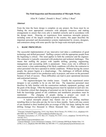
be considered. After this, the components within the system were evaluated; the transfer medium solution,thermally enhanced grout, pile spacing, and the heat pump itself.2.4.1 GSHP SystemsThe earth provides a steady as well as immense heat source and heat medium for thermal transfer use.Deep vaults containing a mercury thermometer were installed beneath the Observatoire in Paris in the late17th century by the French chemist and physicist Lavoisier. These vaults were 27 m deep. In 1778, it wasdetermined through observation and data collection over time that the readings in the earth were constantthroughout the year (EGEC, 2008).Figure 1, summarizing a result of a study completed by Virginia Tech, shows the mean annual earthtemperature throughout the United States. The mean annual earth temperature is found at about 30 feetbelow the surface, and where the subsurface temperature remains relatively constant.Figure 1: Annual Mean Earth Temperature, United State (Virginia Tech).16
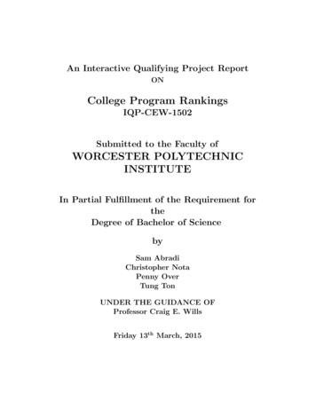
Over time, different methods of GSHPs were created. Figure 2 shows the different GSHP systems. Thesemethods include ground water wells, horizontal coils with direct expansion, horizontal coils with brinecircuit, vertical borehole heat exchangers in co axial form, borehole heat exchangers in U-pipe form, andborehole heat exchangers in spiral form.Figure 2: GSHP – Schematics (EGEC, 2008).Ground Source Heat Pumps are also classified in another way: open and closed loop systems. Open loopsystems require a groundwater or surface water supply to be present. This is a direct one way heat transferwhere the water source will flow through the heat pump system and be discharged. Closed loop systemswork as an underground network. This is a system of ground loop piping, commonly made of a highdensity plastic (HDPE) filled with a working fluid. The fluid flows to deeper points in the earth, nevercoming in direct contact with the soil, acting as the earth-coupled heat exchanger. As the working fluidflows back to the heat pump the actual fluid never leaves the pipes and is re-circulated.17
Different restrictions could prohibit different types of systems. Without a water source, open loop systemscannot be attained. Depending on land availability, certain types of horizontal systems may take up toomuch land. An effective system can be chosen once the parameters of the site are determined.2.4.2 The Heat Transfer MediumThe heat transfer medium is the flowing fluid in a GSHP system. If freezing could present a problem, anantifreeze mixture is used.Due to the extreme low temperatures in Boston during the winter months, antifreeze will be added to thewater medium to ensure that it will never freeze towards the surface. It is suggested that an antifreezesolution be used in any instances where the temperature will be below 40 degrees F, which will withoutdoubt be the case in Boston. There are many different types of antifreeze additives to consider. All ofthem fall into three different categories: alcohols (methanol, ethanol), glycols (ethylene glycol, propyleneglycol), and salts (sodium chloride, calcium chloride, and potassium acetate) (Virginia Tech).The alcohol water solutions will have a low viscosity and higher heat transfer capabilities. In terms of thesystem this translates to mean lower pumping power and a shorter ground loop. Due to the toxicity ofalcohol, this type of solution presents a high level of danger. Methanol is highly volatile and flammablein pure form. Despite the toxicity, methanol has successfully been used over a decade in the heat pumpindustry. Some local regulations prohibit the use of methane, and this must be investigated before use.Ethanol cannot be purchased in pure form, only in denatured form and denaturants have the possibility ofchemically attacking the HDPE piping.Ethylene glycol mixtures are typically used to cool automobiles. One danger in using this substance isthat its sweet taste can attract animals and children and cause harmful ingestion. Due to its toxicity it isgenerally not used for ground heat pump systems. Propylene glycol is a less toxic but far more expensivemixture
Additionally, due to the subsurface characteristics of Boston, MA, deep foundations such as micropiles . 5 are often used to support higher loads for building foundation support. . Engineering design goes beyond following existing standards and specifications. It is the concept of using what you know and more importantly adapting to learn .