Transcription
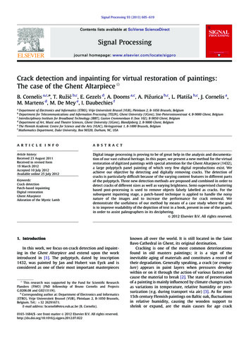
Signal Processing 93 (2013) 605–619Contents lists available at SciVerse ScienceDirectSignal Processingjournal homepage: www.elsevier.com/locate/sigproCrack detection and inpainting for virtual restoration of paintings:The case of the Ghent Altarpiece B. Cornelis a,c,n, T. Ružić b,c, E. Gezels d, A. Dooms a,c, A. Pižurica b,c, L. Platiša b,c, J. Cornelis a,M. Martens d, M. De Mey e, I. Daubechies faDepartment of Electronics and Informatics (ETRO), Vrije Universiteit Brussel (VUB), Pleinlaan 2, B-1050 Brussels, BelgiumDepartment for Telecommunications and Information Processing (TELIN), Ghent University (UGent), Sint-Pietersnieuwstraat 4, B-9000 Ghent, BelgiumInterdisciplinary Institute for Broadband Technology (IBBT), Gaston Crommenlaan 8 (box 102), B-9050 Ghent, BelgiumdDepartment of Art, Music and Theatre Sciences, Ghent University (UGent), Blandijnberg 2, B-9000 Ghent, BelgiumeThe Flemish Academic Centre for Science and the Arts (VLAC), Hertogsstraat 1, B-1000 Brussels, BelgiumfMathematics Department, Duke University, Box 90320, Durham, NC, USAbca r t i c l e i n f oabstractArticle history:Received 23 August 2011Received in revised form19 March 2012Accepted 10 July 2012Available online 25 July 2012Digital image processing is proving to be of great help in the analysis and documentation of our vast cultural heritage. In this paper, we present a new method for the virtualrestoration of digitized paintings with special attention for the Ghent Altarpiece (1432),a large polyptych panel painting of which very few digital reproductions exist. Weachieve our objective by detecting and digitally removing cracks. The detection ofcracks is particularly difficult because of the varying content features in different partsof the polyptych. Three new detection methods are proposed and combined in order todetect cracks of different sizes as well as varying brightness. Semi-supervised clusteringbased post-processing is used to remove objects falsely labelled as cracks. For thesubsequent inpainting stage, a patch-based technique is applied to handle the noisynature of the images and to increase the performance for crack removal. Wedemonstrate the usefulness of our method by means of a case study where the goalis to improve readability of the depiction of text in a book, present in one of the panels,in order to assist paleographers in its deciphering.& 2012 Elsevier B.V. All rights reserved.Keywords:Crack detectionPatch-based inpaintingDigital restorationGhent AltarpieceAdoration of the Mystic Lamb1. IntroductionIn this work, we focus on crack detection and inpainting in the Ghent Altarpiece and extend upon the workintroduced in [1]. The polyptych, dated by inscription1432, was painted by Jan and Hubert van Eyck and isconsidered as one of their most important masterpieces This research was supported by the Fund for Scientific ResearchFlanders (FWO) (PhD fellowship of Bruno Cornelis and ProjectsG.0206.08 and G021311N).nCorresponding author at: Department of Electronics and Informatics(ETRO), Vrije Universiteit Brussel (VUB), Pleinlaan 2, B-1050 Brussels,Belgium. Tel.: þ32 26291671.E-mail address: bcorneli@etro.vub.ac.be (B. Cornelis).0165-1684/ - see front matter & 2012 Elsevier B.V. All rights 7.022known all over the world. It is still located in the SaintBavo Cathedral in Ghent, its original destination.Cracking is one of the most common deteriorationsfound in old masters paintings; it is a sign of theinevitable aging of materials and constitutes a record oftheir degradation. Generally speaking, a crack (or craquelure) appears in paint layers when pressures developwithin or on it through the action of various factors andcause the material to break [2]. The state of preservationof a painting is mainly influenced by climate changes suchas variations in temperature, relative humidity or pressurization (e.g. during transport via air) [3]. As for most15th century Flemish paintings on Baltic oak, fluctuationsin relative humidity, causing the wooden support toshrink or expand, are the main causes for age crack
606B. Cornelis et al. / Signal Processing 93 (2013) 605–619formation. Age related or mechanical cracks can affect theentire paint layer structure, including both the preparation and the paint layers on it. Age cracks are to bedistinguished from premature cracking [2]. The latter aremore dull-edged than those formed when aging andoriginate in only one of the layers of paint. They generallyreveal a defective technical execution at the paintingstage, such as not leaving enough time for a layer todry, or applying a layer that dries faster than the underlying one. A third type is varnish cracks, formed only inthe varnish layer, when it becomes brittle throughoxidation.Cracks form an undesired pattern that can be eitherrectangular, circular, web-shaped, unidirectional, treeshaped or even completely random. The way in whichthey manifest themselves and spread partly dependsupon the choice of materials and methods used by theartist. This makes cracks useful for judging authenticity,as is proposed in [4]. Cracks can also assist conservatorsby providing clues to the causes of degradation of thepaint surface. This can be used for degradation monitoringof the paint layer or a more in-depth study on whichfactors contribute to the formation of cracks, so that stepscan be taken to reduce them [5]. The potential of usingcracks as a non-invasive means of identifying the structural components of paintings is highlighted in [6]. Thecorrelation between the network of cracks on the surfaceand the structure of the panel below is also investigatedin [2] by using multi-layered X-ray radiography. An areawhich is thought to be of great interest to art conservationis content-based analysis where cracks are used forcontent-based retrieval of information from image databases [3].Digital image processing can automatically detect cracklike patterns. In the literature, this process is often referredto as ridge-valley structure extraction [7]. Many types ofimages contain similar elongated structures (e.g. medicalimages of veins and vessels [8], images of fingerprints andsatellite imagery of rivers and roads) and the common goalis to extract or detect these crack-like patterns in order toseparate them from the rest of the image. An overview ofdifferent crack detection techniques can be found in [5].These include different types of thresholding, the use ofmulti-oriented filters (such as Gabor filters) and a plethoraof morphological transforms.In the context of the virtual restoration of digitizedpaintings, crack detection is often treated side-by-sidewith crack removal. Inpainting, which is the imagerestoration task of filling in missing parts of the image,is used for this purpose. The literature contains a vastnumber of general inpainting methods which can beroughly separated into two groups: pixel-based andpatch-based methods. Pixel-based methods aim at replacing one missing pixel at the time [9,10] by speciallyfocusing on structure propagation, i.e. propagation of linesand object contours, from the boundaries of the missingregion to its center. Patch-based methods [11–14], on theother hand, fill in the missing region patch-by-patchensuring in that way better texture propagation. Theyalso consider structural propagation by introducing acertain priority in which the patches are visited.A virtual restoration system to remove cracks ondigital images of paintings was developed in [15]. Theirmethod is based on a semi-automatic crack detectionprocedure, where users need to specify a location believedto belong to a crack network. The algorithm will thentrack other suspected crack points based on two mainfeatures, absolute gray-level and crack uniformity. Oncethe algorithm has completely detected cracks, they can beremoved by interpolation. In [16–18] crack patterns aredetected by thresholding the output of a morphologicaltop-hat transform. Cracks are subsequently separatedfrom brushstrokes (i) by using the hue and saturationinformation in the HSV or HSI colour space and feedingit to a neural network or (ii) by letting a user manuallyselect seed points. Finally, the cracks are inpainted usingorder statistics filtering for interpolation [17], controlledanisotropic diffusion [16] or patch-based texture synthesis [18].The cracks considered here are particular in a numberof ways. Their width ranges from very narrow and barelyvisible to larger areas of missing paint. Furthermore,depending on the painting’s content, they appear asdark thin lines on a bright background or vice versa,bright thin lines on a darker background. In Section 2 weintroduce three different detection schemes, each able todetect bright and dark cracks and each having its ownstrength. Since this masterpiece contains many detailsand some of the brushstrokes are of similar colour andstructure as the cracks, we introduce a semi-supervisedclustering based post-processing step to remove falsepositives. The detection is finalized by combining thecleaned crack maps of each of the three methods usinga simple voting scheme.Additionally, the bright borders that are presentaround some of the cracks (and are accentuated by theway the data set was acquired) cause incorrect andvisually disturbing inpainting results. These borders arethe result of two factors: where a crack is forming, thepaint is pushed upwards and forms a small inclination.Light gets reflected on the ridges caused by this crackingand makes them appear brighter than their immediatesurroundings. Also, during previous cleaning, the surfacepaint on these elevated ridges may have been accidentallyremoved, revealing parts of the underlying white preparation layer. Section 3 elaborates on the improvedpatch-based inpainting for the digital filling of cracksand the inpainting results.In Section 4 the practicability of our technique isconfirmed by means of a case study which consists ofimproving the readability of depicted text in a very smalldetail in one of the panels. We end the paper withconcluding remarks, presented in Section 5.2. Crack detectionCracks can visually be categorized into two classes,bright cracks on a dark background or dark cracks on abright background (see Fig. 1). Mainly dark cracks aretreated in the literature, where they are typically consideredas having low luminance and being local (grayscale) intensity minima with elongated structure [19]. Different crack
B. Cornelis et al. / Signal Processing 93 (2013) 605–619detection techniques include simple thresholding, linedetectors and various morphological filters (see [5] for anoverview). Thresholding does generally not work well dueto the noisy nature of the images and the presence of other‘‘crack-like’’ structures in the image. The varying quality ofthe images and the difficulty of detecting cracks in lowcontrast zones justifies several pre-processing steps. Weintroduce three different crack detection techniques thatcan be applied for the detection of both dark and brightcracks, each having its own strength. A semi-automaticclustering based post-processing step is applied to reducethe number of false detections. We subsequently combinethe results of each technique and hence put to use theirrespective strengths. The procedure for the entire crackdetection is shown in Fig. 2.Furthermore, we identified the need to detect brightborders that surround some of the cracks (as depicted indetail in the upper right corner of Fig. 1 and in Fig. 4)because they cause incorrect and visually unpleasinginpainting results. We will show in Section 3 that theirdetection and treatment as missing regions lead toimproved inpainting.2.1. Pre-detection processingThe detection of cracks in low contrast areas is aparticularly difficult task. To deal with this problem,we introduce a local contrast enhancement step fordarker zones in the image prior to crack detection. This607pre-processing step consists of taking the weighted average of the original grayscale image (Iorig) and its locallycontrast enhanced version (ICLAHE) such that only darkerareas are replaced with a contrast enhanced version. Theresulting image I is constructed as follows:I ¼ ð1 wÞIorig þwICLAHE ,ð1Þwhere the high contrast image ICLAHE is constructed byusing contrast limited adaptive histogram equalization(CLAHE) [20] and the weights w for each pixel aredetermined by blurring (Gaussian kernel with s ¼ 15and mask size 45 45) the inverted image Iorig (see Fig. 3).Due to the noisy nature of the images we performanisotropic diffusion [21] on image I as isotropic blurringwould remove edges too much, which is in fact what wewant to detect. We work on high resolution scans oforiginal photographic negatives (Kodak Safety Film13 18 cm) taken by a professional photographer, thelate Rev. Alfons Dierick, whose material is currentlypreserved in the Alfons Dierickfonds archive of the GhentUniversity. The capturing process (i.e. field of view, lighting, etc.) is undocumented and the images are noisy(an example is given in Fig. 4). Not only were differentchemical processes used to develop the negatives, butsome of them were also acquired at different resolutionsand with different scanning hardware. In strong contrastto the medical world, where standardization made common image processing tools possible, it is very challenging to find a global parameter set for all images underinvestigation. The data set being heterogeneous in nature,the amount of anisotropic diffusion is determined heuristically: the higher the resolution of the images, the moreiterations are chosen for the diffusion.2.2. Detection methodsThree novel crack detection methods are applied forthe detection of both dark and bright cracks. Thesetechniques have complementary strengths, which areexplained in Section 2.4.Fig. 1. Crack types: dark cracks on bright background (top), and brightcracks on dark background (bottom). The width of the mouth is 2.86 cm(approximately 1.13 in) on the panel.2.2.1. Filtering with oriented elongated filtersOriented elongated filters (see Fig. 5) were originallyintroduced to detect and enhance blood vessels of differentthicknesses and orientations in medical images [22]. Theyare used here for the detection of cracks and are ngpreprocessingK-SVDFig. 2. Workflow for the entire crack detection procedure. The optional inpainting preprocessing (see Section 2.5) is applied whenever bright bordersaround the crack are prominently present (e.g. in Fig. 21).
608B. Cornelis et al. / Signal Processing 93 (2013) 605–619I origI CLAHEI (1-w)Iorig wwI CLAHEFig. 3. Local contrast enhancement workflow.derivative of the Gaussian kernel G is calculated asGn ðx,yÞ ¼ nx@Gðx,yÞ@Gðx,yÞþ ny:@x@yð3ÞThe first order partial derivatives of G can be approximatedwith sufficient accuracy by adequately shifting the Gaussian kernels. For example: s s i@Gðx,yÞ1h ,y G x ,y :ð4ÞG xþ@xs22For the filter to be sensitive to vessel- or crack-likestructures the kernel obtained above is combined in thefollowing way:G0n ðx,y,wÞ ¼ Gn ðx þ wnx ,yþ wny Þ Gn ðx wnx ,y wny Þ,Fig. 4. Close-up of Kodak negative scan (showing bright borders aroundthe cracks and noise). The height of one letter (marked in red) isapproximately 0.17 cm (or 0.07 in) on the panel. (For interpretation ofthe references to colour in this figure caption, the reader is referred tothe web version of this article.)by performing linear combinations of 2D Gaussian kernels: 2 x þ y2:Gðx,yÞ ¼ exp 2s2ð2ÞIn order to construct a filter that emphasizes edges orthogonal to a given unit vector n ¼ ðnx ,ny Þ, the directionalð5Þwhere w controls the half-width of the filter. To make thefilter more directionally sensitive we combine shiftedversions of the kernel G0n in a slightly different fashion aswhat is proposed in [22]: a finer sampling grid is used inhorizontal and vertical direction which induces a densersuccession of kernels and results in a smoother filter, lNX1kkG0 n ðx,y,w,lÞ ¼G0n x þ t 1 ,y þ t 2 ,w ,ð6Þ2lN þ 1 k ¼ lNNNwhere t ¼ ðt 1 ,t 2 Þ is a unit vector orthogonal to n and lcontrols the length of the resulting kernel. These filters candirectly be applied to detect cracks brighter than theirbackground. To detect dark cracks it is sufficient to invertthe sign of all filter coefficients and apply this new set offilters on the image I. Examples of oriented elongated filtersfor the detection of dark cracks are shown in Fig. 5.As the filters tend to respond to step-like edges as well,the filtered images are validated by comparing grayvalues of pixels on both sides of the edge pixel at a
B. Cornelis et al. / Signal Processing 93 (2013) 605–619609Fig. 5. Directional kernels G0 n of size 51 51: s ¼ 1:4, w ¼ s, N ¼1 and l ¼ 10s.Fig. 6. Influence of the high threshold (fixed lower threshold):(a) threshold too low, (b) selected threshold, and (c) threshold too high.certain distance and angle (provided by n) in the blurredversion ðB ¼ InGÞ of the image I as defined in Fig. 3. For adark crack, the pixels on each side of the edge pixel needto have a higher grayscale value than the crack pixel andvice versa for bright cracks.The resulting filtered and validated images (one foreach directional filter) are hysteresis thresholded. First,the image is thresholded with a high and a lower threshold. All the high thresholded edges are retained togetherwith low thresholded edges that are connected to them.The low thresholded edges that are not connected to highthresholded edges are discarded. Both thresholds areimage dependent, which forces us to manually determinethem through visual inspection of the results. Note thatwe use a single threshold value for all directionallyfiltered images. The final binary image, marking thelocation of cracks, is formed by combining thethresholded images with a logical OR operation and isreferred to as crack map. We found experimentally thatespecially the value of the high threshold is critical, Fig. 6shows its effect on the resulting crack map. The entireworkflow is depicted in Fig. 7.2.2.2. Multiscale morphological top-hatA popular technique to detect details with particularsizes is the use of a morphological filter known as the tophat transformation [23] which was already successfullyapplied in crack detection [3,17,19]. For the detection ofdark cracks on a lighter background we use the blacktop-hat (or closing top-hat) transform THb ðIÞ which isdefined as the difference between the morphologicalclosing jb ðIÞ of a grayscale image I using a structuringelement b and the input image I and results in a grayscaleimage with enhanced details. Clearly, the structuringelement should be chosen according to the size andnature of the cracks to be detected. However, this processis still an open problem [5]. Recall that the morphologicalclosing operation is defined as dilation followed by erosion. By thresholding THb(I), which in our case is performed automatically by using Otsu’s method [24], wecreate a binary image of details which are most likely tobe dark cracks. A similar technique can be employed forthe detection of bright cracks by replacing the black tophat transform with a white top-hat (or opening top-hat)transform, which is defined as the difference between theinput image I and its opening gb ðIÞ by a chosen structuringelement b.Instead of using the classical top-hat transforms weuse a multiscale morphological approach, introduced in [1]and depicted in the workflow of Fig. 8. The noisy nature ofthe images as well as the multitude of structures havingcrack-like properties can cause many misdetections(undesired for the subsequent inpainting). Both thereduction of the undesired false positives and the detection of cracks of varying size (ranging from very smallhairline cracks to larger areas of missing paint) benefitfrom a multiscale detection scheme. We perform the tophat operation described above with square shaped1structuring elements b of varying sizes (ranging from3 3 to n n pixels, where n depends on the width ofthe crack to be detected2). By choosing a small structuringelement, we extract hairlike cracks but also a lot of otherfine scale structures that do not correspond to cracks.When using a large structuring element, on the otherhand, we detect cracks but coarser structures as well.Next, we automatically threshold the results of thesuccessive morphological filterings using Otsu’s methodto obtain different crack maps, which is an improvementon the detection method of [1] because manual selectionof thresholds is avoided. All the crack maps are subsequently further processed, by bridging pixel gaps and1Using other shapes of similar dimensions did not really affect thedetection process.2n¼ 8 for all images except for the special case of the book of whicha detail is shown in Fig. 4, where n¼ 10.
610B. Cornelis et al. / Signal Processing 93 (2013) 605–619For each filtered ilteredimagemaThresholdw.hysteresisCombinemaps (OR)Fig. 7. Filtering with elongated directional filters workflow.Top-Hat thresholdingRemove smallobjectsCrack mapOriginalBase mapConnect objects3x3nxnFig. 8. Multiscale morphological top-hat workflow.removing isolated or small groups of pixels as much aspossible.3We now combine the resulting crack maps fromsuccessive scales in a novel way. The crack maps of thethree smallest scales are added to form our base mapwhich is used as a reference for selecting cracks in crackmaps corresponding to coarser scales. The final crack mapresults from the base map by adding only objects(i.e. groups of connected pixels) from maps at coarserscales that are connected to the base map. This way ofworking has the major advantage that unwanted largerstructures such as the mustache of Adam in Fig. 1 or theletters in the book image depicted in the example of Fig. 8,more often detected at larger scales, will not be includedin the final map while cracks are still allowed to growthrough successive scales.2.2.3. K-SVD for crack enhancementThe third technique proposed in this paper relies onthe use of the K-SVD algorithm [25], which is used forconstructing and adapting dictionaries in order to achievesparse signal representations and which was neverapplied before in a crack detection context. It is aniterative method that alternates between sparse codingof the data based on the current dictionary and theupdating of dictionary atoms to better fit the data.The K-SVD algorithm works on small (usually overpffiffiffi pffiffiffilapping) patches x 2 Rn of size n n. The learning ofthe over-complete dictionary D 2 Rn k with a fixed number of atoms k and sparsity constraint L (i.e. each patch iscomposed of no more than L dictionary atoms) can bedescribed by the following optimization problem:minJX DaJ22a,D3Standard parameterless Matlab functions are used in the followingsequence: bridge, clean and fill. These are followed by an additionalcleaning step, removing objects of size smaller than 20, 30, 40,y, 70pixels for the six successive morphological filtered images.s:t: Jal J0 r L,ð7Þwhere the column vectors (xl) of X are M image patches onwhich the dictionary D is learned. Each dictionary atomdi 2 D, for i ¼ 1 . . . k, is a unit vector in the ‘2 -norm. Thecolumn vector al of a is the sparse coefficient matrix vectorcorresponding to the patch xl and Jal J0 denotes the number
B. Cornelis et al. / Signal Processing 93 (2013) 605–619of non-zero elements in the vector. K-SVD is an iterativemethod specifically designed to minimize the energy of (7)and where each iteration consists of two steps. The first oneis the sparse coding step which addresses the problem offinding the best decomposition Dal for each patch xl. To thisend, a greedy orthogonal matching pursuit (OMP) is used. Thesecond step, called the dictionary update step, optimizes theleast-square problem (i.e. the ‘2 -norm in (7)) for each atomindividually while keeping the remaining atoms fixed andupdates the corresponding non-zero coefficients in a. K-SVDis used in this context as a method for enhancing crackswithin the image by training an optimal dictionary D for eachimage and altering the coefficient matrix a during reconstruction in an appropriate way.A dictionary (k¼128) is trained on overlapping patches ofthe image I, containing cracks, hence producing an overcomplete dictionary tweaked to that image. Patches must bepffiffiffisufficiently large to capture crack-like edges ð n ¼ 16Þ andthe sparsity constraint is very strict (L equal to 1 is typicallychosen). After training (using 20 iterations, and on a sufficiently large number of patches), some dictionary elementswill contain information for the ‘‘optimal’’ representation ofcracks due to the strong sparsity constraint. We use thetrained dictionary to reconstruct an image patch Ic containingonly cracks, which obviously favours the usage of crack-likedictionary elements. This can be observed in the histogram ofdictionary usage depicted in Fig. 9. Choosing an appropriateIc is straightforward: examples are given in Fig. 10. Whenreconstructing the image I, the number of elements in thecoefficient matrix a, corresponding to less used dictionaryelements for Ic are put to zero. Note that the dictionary itselfremains unaltered. The rule for zeroing out coefficients is asfollows:(ali if Ja0i J0 4 b maxJa0i J0 ,ð8Þ8l, ali ¼0 otherwise,Initial dictionary Dof dictionary element di, l the index of the patch extractedfrom I and b a parameter controlling the amount of coefficients to put to zero. The default value for b is chosen as 0.5and its value is lowered when it is observed that aninsufficient number of cracks are reconstructed, but thishappens rarely and hence user interaction is kept to aminimum. Through this procedure, non-crack dictionaryelements are omitted during the reconstruction of I.Note that the DC component of each patch is subtracted before training and reconstruction, which resultsin a reconstructed image that can contain negative valuesas well. As a final step the image is hysteresis thresholdedin the same fashion as described in Section 2.2.1 for thedetection of bright cracks while for the detection of darkcracks the reconstructed image needs to be inverted first(results are shown in Fig. 11).2.3. k-Means clustering based semi-automaticpost-processingIn the three proposed methods some objects, having asimilar structure as cracks (such as eyebrows, eyelashesand the mustache in the Panel depicting Adam or theletters of the book in the Annunciation to Mary panel) areFig. 10. Candidate image patches, Ic, for training of dictionary.di occurrencewhere a0 is the coefficient matrix when reconstructing thecrack-only image patch Ic, Ja0i J0 the corresponding total usage611thd α i0Most used d iFig. 9. Dictionary usage histogram and most used di ðth ¼ b maxJa0i J0 ).
612B. Cornelis et al. / Signal Processing 93 (2013) 605–619Fig. 11. K-SVD results (left: original; middle: reconstructed (inverted); right: thresholded).Fig. 12. Results of detection with K-SVD (left: original detection; right:after post-processing with k-means clustering).sometimes falsely labelled as cracks. We propose aclustering based semi-automatic method to assist infiltering out those structures.First the binary map, obtained by applying one of themethods described above, is thinned to obtain one-pixelwide cracks [26]. Crack pixels are linked together into listsof coordinate pairs,4 where a crack junction is encountered. The list is terminated and a separate list is generated for each of the branches. In this manner, each crack isbroken down into segments which can be treated asseparate objects. For each of these objects, a number offeatures are calculated: colour (the object’s mean colourvalues in RGB and HSV colour space) and physical properties such as length, orientation and eccentricity. Next tothese, the colour values of the immediate region surrounding the crack are computed as well. Recall thatcracks can sometimes be surrounded by a bright border(as explained in the beginning of Section 2) which can bea crucial feature for discerning cracks from non-cracks.As the last feature, a spatial density value is assigned toeach object, which will prove to be a very significantfeature (e.g. eyebrow edges typically belong to moredense regions than crack edges in the image as can beobserved in Fig. 12). All these features are combined into afeature vector and serve as input to a k-means clustering.It is now a matter of manually removing undesiredclusters which correspond to falsely labelled objects, bysimply specifying one or more cluster numbers. Results4Matlab functions are available on: http://www.csse.uwa.edu.au/ pk/Research/MatlabFns/index.html#edgelink.Fig. 13. Results of detection with elongated filters (left: original detection;right: after post-processing with k-means clustering).are shown in Figs. 12 and 13 for k equal to 3 and after theremoval of one cluster.2.4. Combining the results of each methodDuring experimentation, it became clear that eachmethod has its own strength and weakness. Filtering withthe elongated oriented filters usually detects most of thecracks since a single value for s (which controls the widthof the filter, see Section 2.2.1) will generate a highresponse from elongated structures of various widths.This is one of the major advantages of this technique,but also its weakness since other elongated structurestend to have a high response after filtering as well. Themultiscale morphological approach described in Section2.2.2 works well on images containing letters and significantly reduces the number of mislabelings comparedto the classical top-hat transform. Moreover, thanks to theintroduced notion of scale when constructing the finalcrack map, a distinction between fine and coarser cracksis possible. However, on images such as parts of the faceof Adam, the method can miss some of the very smallcracks during
found in old masters paintings; it is a sign of the inevitable aging of materials and constitutes a record of their degradation. Generally speaking, a crack (or craque-lure) appears in paint layers when pressures develop within or on it through the action of various factors and c