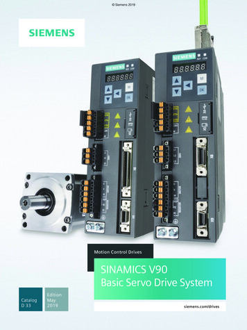
Transcription
Operating InstructionsInstallation InstructionsMedium-Voltage DriveSINAMICS PERFECT HARMONY GH150Type 6SL3825Edition05/2020www.siemens.com/drives
19.06.2020 09:58V14.00
Introduction1Safety instructions2Medium-Voltage DriveDescription3SINAMICS PERFECT HARMONYGH150Type 6SL3825Preparations for use4Assembly5Electrical re parts10Disposal11Operating InstructionsInstallation InstructionsEdition 05/2020Service & SupportATechnical data and drawingsBQuality documentsCAdditional documentsD
Legal informationWarning notice systemThis manual contains notices you have to observe in order to ensure your personal safety, as well as to preventdamage to property. The notices referring to your personal safety are highlighted in the manual by a safety alertsymbol, notices referring only to property damage have no safety alert symbol. These notices shown below aregraded according to the degree of danger.DANGERindicates that death or severe personal injury will result if proper precautions are not taken.WARNINGindicates that death or severe personal injury may result if proper precautions are not taken.CAUTIONindicates that minor personal injury can result if proper precautions are not taken.NOTICEindicates that property damage can result if proper precautions are not taken.If more than one degree of danger is present, the warning notice representing the highest degree of danger will beused. A notice warning of injury to persons with a safety alert symbol may also include a warning relating to propertydamage.Qualified PersonnelThe product/system described in this documentation may be operated only by personnel qualified for the specifictask in accordance with the relevant documentation, in particular its warning notices and safety instructions. Qualifiedpersonnel are those who, based on their training and experience, are capable of identifying risks and avoidingpotential hazards when working with these products/systems.Proper use of Siemens productsNote the following:WARNINGSiemens products may only be used for the applications described in the catalog and in the relevant technicaldocumentation. If products and components from other manufacturers are used, these must be recommended orapproved by Siemens. Proper transport, storage, installation, assembly, commissioning, operation andmaintenance are required to ensure that the products operate safely and without any problems. The permissibleambient conditions must be complied with. The information in the relevant documentation must be observed.TrademarksAll names identified by are registered trademarks of Siemens AG. The remaining trademarks in this publicationmay be trademarks whose use by third parties for their own purposes could violate the rights of the owner.Disclaimer of LiabilityWe have reviewed the contents of this publication to ensure consistency with the hardware and software described.Since variance cannot be precluded entirely, we cannot guarantee full consistency. However, the information in thispublication is reviewed regularly and any necessary corrections are included in subsequent editions.Siemens AGLarge Drives ApplicationsVogelweiherstr. 1-1590441 NÜRNBERGGERMANYDocument order number: 6SL3825 06/2020 Subject to changeCopyright Siemens AG 2020.All rights reserved
Table of contents1Introduction.131.123About these instructions.13Safety instructions .152.1Warning symbols on the device .152.2Qualified personnel .152.3The 5 safety rules.152.4Safe handling .162.5Electromagnetic fields in electrical power engineering installations .182.6Components that can be destroyed by electrostatic discharge (ESD).192.72.7.12.7.22.7.32.7.42.7.5Information for persons responsible for plants and systems.20Proper usage.20Grounding concept.21Installation site safety.21Measures for operator protection in electromagnetic fields .22Requirements for the circuit breaker provided by the customer.222.8Residual risks.232.9Security information .25Description.273.1Area of application .273.23.2.13.2.23.2.33.2.4Safety concept .27Safety components and functions .27External safety components.28Protection and monitoring functions of internal components .28Protection and monitoring functions for external components .283.3Design .293.4Control Module.303.5Basic Line Module.303.6Motor Module employing M2C technology.303.73.7.13.7.23.7.33.7.4Re-cooling unit .32Cooling unit requirements .32Operating principle of the re-cooling unit .33The internal deionized water circuit.33The external raw water circuit .343.83.8.13.8.2Components.35Control Unit .36Power Stack Adapter .36SINAMICS PERFECT HARMONY GH150 6SL3825Operating Instructions 05/20205
Table of 8.133.8.143.8.14.13.8.14.23.8.15Terminal Modules.38Power cell.38IGBT module .38Capacitor bank .39Door limit switch .39Electromechanical door interlocking system .39Precharging.40Actual value sensing .40Common power supply .40Field of application .40Connections .41Interface description.41Touch screen operator panel .42DC/DC converter.43Line filter.43SIRIUS safety relay.43Auxiliary power supply .441 AC auxiliary voltage .443 AC auxiliary voltage supply .44Customer terminal strips .443.93.9.13.9.23.9.3Interfaces .45Hydraulic interfaces.45Electrical interfaces .45DRIVE-CLiQ interface .46Preparations for use .474.1Requirements for installation location .474.24.2.14.2.2Inspections when the equipment is received .47Checking shock and tilt indicators.47Checking the load handling attachments sport.49Transport markings .49Transport requirements.49Observe center of gravity .50Transport with a fork-lift truck.50Transport with a crane .51Using lifting rods.51Transporting transportation units packed in boxes .53Transporting a re-cooling unit .544.44.4.14.4.24.4.34.4.44.4.5Unpacking the cabinets.55Removing the packaging.55Removing load securing devices .55Lifting the cabinet off the transport pallet .56Opening doors in preparation for use.56Checking the shock and tilt indicators inside the g the drive .57Storing a device .58Storing fans .60Storing re-cooling units .60SINAMICS PERFECT HARMONY GH150 6SL3825Operating Instructions 05/2020
Table of contents5678Assembly .615.1Safety instructions for assembly .615.2Tools required .625.3Screwing the transport units together .635.4Connect to the foundation .645.55.5.1Connecting cabinets.65Connecting the interface cable.655.6Connecting the water circuits .66Electrical connection.696.1Safety instructions for electrical connections .696.2Electromagnetic compatibility.716.3Potential concept.746.4Cable cross-sections.746.5Connecting ground.756.6Laying the signal lines.766.7Connecting the auxiliary voltage .776.86.8.16.8.26.8.3Connecting power cables.77Preparations.77Procedure.79Shield connection.796.9Connecting the re-cooling unit to the drive.806.10Interconnecting optional connections.806.11Fastening the cable ducts with cable ties.81Commissioning .837.1Commissioning.837.2Safety instructions for commissioning.837.3STARTER software.84Operation.858.1Safety instructions for operation.858.2Operating the converter .868.38.3.18.3.1.18.3.1.2Functions.86Monitoring functions and protective functions .86Insulation monitoring .87Tripping of the circuit-breaker in case of undervoltage .888.48.4.18.4.28.4.2.1Fault and system messages .88Indicating and rectifying faults.88Diagnostics via LEDs .89LEDs of the Power Stack Adapters.89SINAMICS PERFECT HARMONY GH150 6SL3825Operating Instructions 05/20207
Table of contents8.4.2.29LEDs of the Sirius safety relay .90Maintenance .919.1Safety instructions for maintenance .919.29.2.1Grounding the system .93Grounding using the grounding harness .939.3Opening the device .4.3.59.4.3.69.4.3.7Preventive maintenance.95Inspection.95Checklist for preventive maintenance work.95Visual inspections .96Equipment for visual inspections.96Checking the isolating clearances.96Checking hoisting solenoids and security bolts.97Checking the plug connections. .97Checking the cable and screw terminals.97Inspecting door limit switches .97Checking the cooling circuit .979.59.5.19.5.1.19.5.1.2Maintenance.98Replacing a fan .98Replacing fans, from the front .98Replacing fans, from the back.999.69.6.1Cleaning .100Cleaning aluminum parts nents that can be replaced .103Torques .103Replacing the AVT combination module .105Replacing the current transformer.106Replacing the precharging transformer.107Replacing the precharging rectifier .108Replacing a power cell .109Replacing a diode stack .115Discharging the snubber circuit capacitor .115Removing .116Installing .122Replacing water sensors.124Replacing the TP900 operator panel .126Replacing the CompactFlash card .12710Spare parts .12911Disposal.131811.1Information according to Article 33 of the REACH regulation .13111.2Disposing of packaging material .13111.3Removing device components and old devices .132SINAMICS PERFECT HARMONY GH150 6SL3825Operating Instructions 05/2020
Table of contentsAService & Support.133BTechnical data and drawings.135B.1Standards and regulations .135B.2Environmental conditions .136CQuality documents.139DAdditional documents .141Index.143TablesTable 3-1Deionized water requirements.33Table 3-2Raw water requirements .35Table 3-3DRIVE-CLiQ interface .46Table 6-1Cable cross-sections .74Table 6-2Cleaning agents and grease .78Table 8-1LEDs of the Power Stack Adapters .89Table 8-2LEDs of the Sirius safety relay .90Table 9-1General checklist for preventive maintenance work.95Table 9-2Control Module: Checklist for preventive maintenance work .96Table 9-3Tightening torque for screws .103Table 9-4Tightening torques for screw terminals for copper cables without cable lug 1).104Table B-1Standards and regulations .135Table B-2Climatic environmental conditions.136Table B-3Mechanical ambient conditions .136Table B-4Other ambient conditions .137FiguresFigure 2-1ESD information .19Figure 3-1Example – Design of the converter .29Figure 3-2Block diagram: Basic Line Module with diodes .30Figure 3-3Block diagram: Motor Module employing M2C technology .31Figure 3-4Interface overview of Power Stack Adapter 5 .37Figure 3-5Power cell.
Medium-Voltage Drive SINAMICS PERFECT HARMONY GH150 Type 6SL3825 Operating Instructions Installation Instructions Edition 05/2020 Introduction 1 Safety instructions 2 Description 3 Preparations for use 4 Assembly 5 Electrical connection 6 Commissioning 7 Operation 8 Maintenance 9 Spare parts 10 Disposal 11 Service & Support A Technical data and drawings B Quality documents C .