Transcription
Changes in Arc Flash-2018
IEEE-1584 review and meeting update DC Expected Date of new StandardAgendaDavid Rewitzer,PE, CEM Standards Changes 70E NEC Electrical Safety Workshop (ESW) Statistics Analysis
IEEE-1584 Review and Meeting Update
IEEE-1584 was born in early 2000’sTheory inPracticeTurn of theCentury Decided on wide range of currents and voltages Raised 75,000 in funding Used 20 cubic inch box Tested MCC’s using a smaller size box Testing facilities – Square D in Cedar Rapids & Ontario Hydroin Toronto Bussmann played a big roll as well Navy got involved Wanted to see how an arc flash would damage ship Built a 15’ cube Obtained funding for 13.8kV testing Completed document went through a robust approvalprocess Three rounds of 100s of questions Approved June 2002 (2 year cycle)4
Based on the results of 300 arc flash tests Four calculation criteria:IEEE 15842002Developing the2002 Revision1.2.3.4.Systems less than 1000 VSystems from 1000 to 15,000 VIncident energy (cal/cm2)Flash hazard boundary (AKA arc flash boundary) 85% rule Slow burn vs. Rapid Energy Release 125kVA transformer rule Based on data, would not sustain an arc 2-second rule Would leave the arc with-in two seconds5
Questions immediately aroseIEEE 1584Revision ProcessBegins1. What if the electrodes were horizontal instead ofvertical?2. What about difference size enclosures?3. What about DC arc flash?PCIC established a collaboration committeebetween IEEE and NFPA 6.5 Million Requested 3.5 Million Received Recommended 10-year Project AuthorizationRequest (PAR) PAR extension was granted until 12/31/176
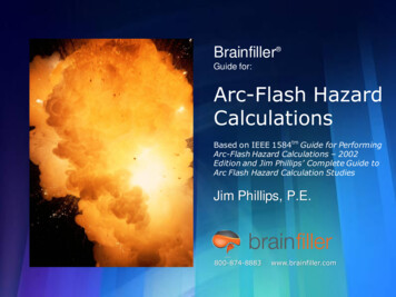
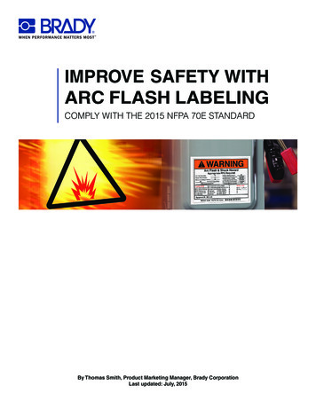
IEEE 15841700 TestsConductedVoltage Number of tests208V (3ph) 240V (1ph)195480V400600V3402700V3204160V18014.3kV2707
New standard makes modeling more complexIEEE 1584Study Complexity Proposed variables Configurations (VCB, VCBB, HCB, VOA, HOA)VocIbfWorking DistanceDuration (Breaker or fuse curve)GapEnclosure Size Box Size & Gap defaults to conservative NEMA size and gapdistance8
The 1584 Committee decided to conduct testsusing five configurations VCB – Vertical electrodes in a Cubic Box (IEEE 2002) Load side of BKRIEEE 1584TestConfigurations VCBB – Vertical electrodes in a Cubic Boxterminated in a “Barrier” line side of BKR VOA – Vertical electrodes in Open Air (IEEE 2002) HOA – Horizontal electrodes in Open Air HCB – Horizontal electrodes in a Cubic Box Busbar HCBB was considered but HCB was considered worstcase9
IEEE 1584Comparison ofResults10
Blast Pressure Injury potential based on fault level Slow burn vs. Rapid Energy Release Sound PressureIEEE 1584Other Parameters Risk of severe hearing damage Tests at 4,160 volts have produced sound levelsupwards of 160 dB at distances of more than 3-meters Light Bright summer day is 100,000 lux (light intensity) 1 lux 1 lumen per square metre squared Tens of millions of lux have been measured during arcflash testing Enclosure Size (now a variable) Based on standard NEMA sizes11
125kVA Rule will not be in the new textStudyComplexityStandard practicestaken out Instead a proposal was made – “No tests weredone at 208V and less than 2500A, thereforeshould not be considered.” 85% rule will not be in new text Statistical deviation was such that confidence informulas So no need to have this rule 2 second rule will not be in new text12
IEEE 1584and 1584.1Two DocumentsIEEE-1584-2018Technical InformationIEEE-1584.1-2018Deliverable Requirements
Design Engineers / OwnersSo WhatDoes ThisMean to Me? Arc flash analysis per 1584.1 Engineers to collect data? Study Engineers Consistency within your own group Plan the data collection Manufacturers Make data visible so we can collect it withouttaking energized equipment apart14
Direct Current
Used same methodology as AC for now “Arc Flash Calculations of Exposures to DC Systems” Doan, D.R.,IEEE Transactions on Industry Applications, Vol. 46 No.6.IEEE 1584Two landmarktechnical paperschanged theunderstanding ofDC arc flash Equations included in the informative annex of the 2012 Edition ofNFPA 70E and remain in Annex D of the 2015 edition Helped elevate the discussion of DC arc flash calculations “DC Arc Models and Incident-Energy Calculations,” R.F.Ammerman, T. Gammon, J.P. Nelson and P.K. Sen, IEEETransactions on industry Applications, Vol. 46, No. 5 Introduced Gap variable16
Iarc 0.5*IbfIEM 0.01*Vsys*Iarc*Tarc/D2IEEE 1584DC Arc FlashFormula in 70EWhere:IEm Estimated DC arc flash incident energy at the maximum powerpoint – cal/cm2Iarc Arcing current - AmpsIbf System bolted fault current - AmpsVsys System voltage – VoltsTarc Arcing time - SecondsD Working distance – cm Assume that the maximum available short-circuit current is 10* the 1 minuteampere rating “For exposures where the arc is in a box or enclosure, it would be prudent toconsider additional PPE protection beyond the values shown in Table130.7(C)(15)(b)”17
IEEE 1584DC Arc Flash DOE Funding 3-yr DC arc flash research withEPRI and Sandia Labs Sent out DC arc flash problem with same variables Got back results anywhere between 7-124 cal/cm2 Any Documented Cases DC arc flash burns? Not Many18
Preliminary model shows promiseIEEE 1584DC Arc Flash Testing shows that consistent arcs can bereproduced. Need more testing to verify model Preliminary results Is arc sustainable? Yes- However, depends oninductance in circuit Current formulas including 70E seems conservative Current-Energy remains constant Arcs vs. Arc Flash19
New Research on Hazards of DCIEEE 1584DC Hazards forBatteries Chemical Lead Acid Shock Arc Flash Thermal Poisonous Gas Hydrogen20
NFPA-70E & NEC
NFPA-70E2018Global Changes New Terminology – Replaced “accident” with “incident” “accidental” with “unintentional” “accidentally” with “unintentionally” “short circuit current” with “available fault current” Reduced DC threshold from 100vdc to 50vdc Aligns with OSHA CFR 1910.303 – 50vdc NFPA 70E Table 130.4(D)(b)- DC shockboundaries
Tenth Edition 2015 Emphasis on risk From arc flash hazard analysis to arc flash risk assessmentNFPA 70EHistory Prohibited approach deleted Category 0 removed from PPE table Electrical Safety Program to include maintenance conditions Arc flash label to include IE or table category BUT NOT BOTH Eleventh Edition 2018 Aligned LOTO with OSHA 1910.147 Electrical Safety Program to include Inspection Human factor/Human error Incident Investigation Job Planning Risk Assessment Procedure Hierarchy of risk controls Removal 40cal/cm2 reference23
A. Employer Responsibility1. Establish, document, and implement practices andprocedures MOPs, SOPs, PPE, etc70E – 105.3Responsibilities2. Provided employees with training in practices andprocedures On-the-Job, ClassroomB. Employee Responsibility Shall comply with the practices and proceduresprovided by the employer24
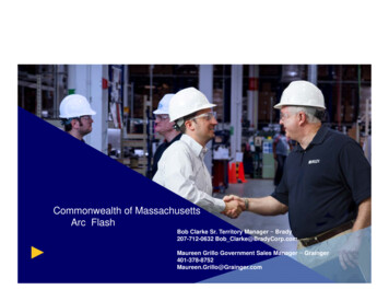
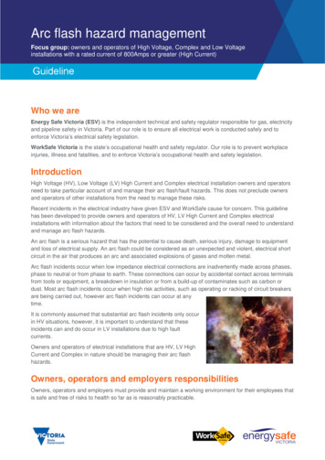
The Arc-FlashHazardWarning LabelThe Final Product 25
40 cal/cm2 Restriction RemovedNFPA -70E2018 130.7 (A) Informational Note 3 – removedfrom 2018 version Used to warn that “greater emphasis may be necessary with respectto de-energizing” equipment that exceeds 40 cal/cm2Changes26
NFPA -70E2018Is it required that Irelabel my facility?130.5(H) Exception 1 “ .Labels applied prior to the effective date of this edition (2018)shall be acceptable if they complied with the requirements forequipment labels in the standard in effect at the time the labels wereapplied.”27
ElectricalSafetyProgram(ESP)Risk AssessmentProcedure(Performed beforework is started) Identify hazards Assess risks Implement risk control according to ahierarchy of methods Elimination Substitution Engineering controls Awareness Administrative controls PPE*Example of Risk Assessment – Annex F28
Hazard Source of harm – injury, damage or deathNFPA 70E2018 RiskRisk AssessmentTerminology Risk Assessment Combination of the likelihood of harm occurringand the severity of that harm A process of hazard identification, risk analysis andrisk evaluation*Example of Risk Assessment – Annex F29
NFPA 70E2018ExampleWhat is a RiskAssessment forShock? Likelihood of making electrical contact Is electrical contact possible when crossing therestricted approach? Not: Can the worker be careful enough to avoid theelectrical shock? Severity of harm Could electrical contact result in harm (e.g. burns,loss of body parts, or death)? Not: It’s ok since I've been shocked before with nolasting effect*Example of Risk Assessment – Annex F30
1. Elimination-o Physically removing the hazard – TURN IT OFF2. Substitution-o Replace with non-hazard equipment – ARC-RESISTANTSWITCHGEARHierarchy ofControls3. Engineering controls-o Isolate workers from hazard – REMOTE RACKING DEVICE
4. Warning/Awarenesso Making workers award of hazards and risks – SIGNS, WARNINGLIGHTS5. Administrative Controlso Standardize the way to perform task – DEVELOP POLICIES,TRAININGHierarchy ofControls6. Personal Protective Equipment (PPE)o Reduces the effects in attempt to make injury survivable –AR CLOTHING, SAFETY GLASSES etc.
Hierarchy ofControlsIV AWARENESS33
I. Job Safety Planning and Job BriefingNFPA 70E2018Safety Planning110.1(I)1. Job Safety Planning1.2.3.Be completed by a qualified personBe documentedInclude the following informationa)b)c)d)e)Job and task descriptionIdentify hazardsShock assessmentArc flash assessmentWork procedures, special precautions, and energy source controls2. Job Briefing – Shall cover the job safety plan3. Change in Scope – Additional planning to occur ifchanges occur34
NFPA 70E2018Article 120:Lockout/Tagout Additions to 120.5 (7) regarding “adequatelyrated” portable test instruments Exception 1 added to allow operators to use permanentlyinstalled meters rather than handheld meters to testconductors and circuit parts Exception 2 added to allow non-contact test instrumentsfor electrical systems over 1000V35
NEC 2017(NFPA 70)Article240.87Arc FlashReduction Where installed overcurrent device is rated oradjustable to a continuous current trip settingof 1200 A or higher, 240.87 A and B applyA. Circuit breaker location must be documented andavailable to authorized personnelB. Methods to reduce clearing time:1. Zone-selective interlocking (ZSI)2. Differential relaying3. Energy-reducing maintenance switching with localstatus indicator4. Energy-reducing arc flash mitigation system5. An instantaneous trip setting that is less than theavailable arcing current6. An instantaneous override that is less than theavailable arcing current7. An approved equivalent means36
Stastistics
ElectricalFatalitiessince the1990sWorkplace fatalitiesdeclined 41%SW2016-30 Presentation38
ElectricalShocksBy the Numbers Nearly 6000 fatalities from 1992-2012 98% involve electrocutions About 40% involve voltages under 600V About 40% involve overhead power line contactSource-NFPA-70E Annex K39
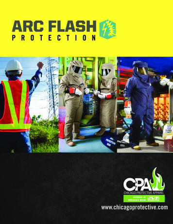
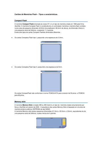
FATAL OCCUPATIONAL INJURIESFatalitiesBetween2011 and2015ESW 2018-39-Reframing ourview of workplace electricalinjuries2011-2015 Occupational Fatalities by Event/TypeYear2011Total Occupational Fatalities 4,6932012 2013 2014 2015Total4,628 4,585 4,821 4,836 23,563Type of Event of ExposureTransportation Incidents1,937Slips, Trips, and Falls6817047248188003,727Violence/Injuries byPersons/Animals7916037737657033,635Contact with Objects andEquipment7107237217157223,591Exposure to Electricity174156141154134759Fire or Explosion1441221491371216731,923 1,865 1,984 2,0549,763
ElectricalFatalities Between2011 and 2015ESW 2018-39-Reframing our view ofworkplace electrical injuries
Non-ElectricalFatalitiesBetween 2011and 2015ESW 2018-39-Reframing our view ofworkplace electrical injuries
Thank YouConnect with meon LinkedIn43
Based on the results of 300 arc flash tests Four calculation criteria: 1. Systems less than 1000 V 2. Systems from 1000 to 15,000 V 3. Incident energy (cal/cm2) 4. Flash hazard boundary (AKA arc flash boundary) 85% rule Slow burn vs. Rapid Energy Release 125kVA transformer rule Based on data, would not sustain an arc 2 .