Transcription
Commonwealth of MassachusettsArc FlashBob Clarke Sr. Territory Manager Brady207-712-0632 Bob Clarke@BradyCorp.comMaureen Grillo Government Sales Manager Grainger401-378-8752Maureen.Grillo@Grainger.com
Agenda IntroductionsGraingerBradyNFPA 70E 2015Arc Flash AssessmentComponents of Arc Flash AssessmentCommon mistakes in an Arc Flash programProposed NFPA 70E 2018
Supporting the Commonwealthof Massachusetts Statewide contract holder FAC94 - MRO Stateside contract holder HSP41 – LabSupplies More than 1 million products Inventory Management Solutions Grainger.com and CommBuys Branches Technical Support
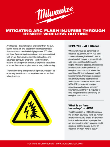
2015 NFPA 70E20122015Electrical hazard analysisElectrical hazard riskassessmentShock hazard analysisShock risk assessmentHazard identification andrisk assessmentRisk assessmentARC FLASH HAZARDANALYSISARC FLASH RISKASSESSMENT
Arc Flash Risk AssessmentRisk Assessment ‐ “An overallprocess that identifies hazards,estimates the potential severityof injury or damage to health,estimates the likelihood ofoccurrence of injury or damageto health, and determines ifprotective measures arerequired.”CRITICAL TO DETERMININGARC FLASH LABELINFORMATION & PPE
What is required? NFPA 70E 2015 Arc Flash Risk Assessment todetermine if there is an ArcFlash Hazard If there is a hazard, employersmust determine the risk toemployees, safe work practicesand levels of personal protectiveequipment (PPE)– OSHA General Duty Clause
What Requires a Label?AND MORE!
Methods for Performing Your Arc FlashRisk AssessmentPPE CategoriesIncident Energy(NFPA)Analysis (IEEE)IEEE 1584 provides details onthe theory and calculationsused to determine the danger aworker could be exposed to.Specific to the actualinstallation and represents alltasks.Categorizes tasks andequipment condition to indicateif PPE is required.If required, the PPE category (1through 4) is then determinedbased on equipment type,voltage, short-circuit current,and fault clearing time.
Comparing the Two – Short Circuit StudyIEEENFPA Establishes thecalculated short-circuitcurrent which allow thecalculation of specificincident energy levels Often applied withoutknowing the shortcircuit Assume short circuitcurrent is withinNFPA limitsAssuming short circuit current may leave worker over orunder protected
Comparing the Two – Equipment EvaluationIEEE Short Circuit Study Identify equipmentthat is insufficient towithstand ratings Specific IncidentEnergy Arc flashrisk level reductionstrategiesNFPA This method doesnot calculate shortcircuit study
Comparing the Two – OvercurrentProtective Device Coordination StudyIEEE Looks at specificovercurrent protectivedevice characteristicsand arc flash duration Allows for overcurrentprotective devicecoordination studyNFPA Does not take intoaccount overcurrentdevice settings Assumes faultclearing timesAssuming fault clearing times mayleave worker over or under protectedImproper coordination can lead tohigher arc flash energy or nuisancetripping
Comparing the TwoIEEENFPA Requires completeelectrical system datacollection Results in the creation ofan updated single linediagram Looks at pieces ofequipment individually
Conclusion – Recommendation onMethodOverall the best practice option the incident energyanalysis method Based on actual electrical distribution system based fromdata collection Deliverables should include all the input data andcalculations results (record keeping), as well asan updated SLD for your facility. Employees are accurately protected
What Should Be Included in a Arc FlashRisk Assessment? Data CollectionPower System ModelingFault Current StudyEquipment EvaluationCoordination StudyArc Flash CalculationsGeneral ObservationsReport and DocumentationLabel Creation andInstallation
Data Collection Typically is about 53% of total project time and spent on site.Requires Field engineer to put on his PPE, open panels, controlcabinets, disconnects, etc (anything that needs to get labeled).andcollects data.They are looking at breakers and fuses (manufacturer, type, ratings,settings), as well as wire size and wire length.This data is used to build the system model
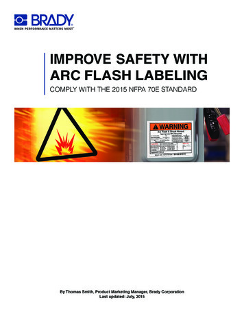
ProcessPower System Modeling This where a third party software would be used to take all the datawe collected and draw a single line diagram. The single line drawing is "smart" and contains inputs for the datawe collected. On paper it just looks like a schematic diagram, butit's a living/breathing model.
ProcessPower System Modeling
ProcessFault Current Study Performed to determine the maximum current that could flowthrough an electrical distribution system after a “fault” orabnormal condition occurs. ie.panels switches The available fault current at each point in the system is one of themain factors that drives the arc flash potential. The results of the fault current study are used in the arc flashcalculations.
ProcessFault Current Study
ProcessEquipment Evaluation Compares the results of our fault current study to the actual ratingsof the equipment (we gathered the actual ratings during datacollection) and then let the owner know if we find any insufficientratings. Every circuit breaker and fuse has an interrupting rating or awithstand rating. Basically, they are manufactured in such a way that if a fault occurs,the breaker should trip or the fuse should "blow" safely. When an electrical system is designed, the engineers do a faultcurrent study and specify fuses/breakers with the appropriateinterrupting ratings so things trip and "blow". If a breaker or fuse is rated improperly, then instead of tripping thebreaker sees a fault current greater than what it's rated, it could failcatastrophically.
What can happen if Device fails Catastrophically? .
ProcessEquipment Evaluation
ProcessCoordination Study Looks at the trip curves of overcurrent protective devices to makesure they don't overlap, and to ensure the breaker settings arecorrect. If there's an issue, you want 1 breaker to trip. We look at breakersand settings and let clients know if there are issues and makerecommendations to fix them if possible.Coordination Study Results:During the field survey of the BSC1 facility, it was found that only 1 circuit breaker had adjustabletripsettings. The SKM TCC plot containing the 400 ampere main circuit breaker for panel HB can befound inAppendix C. This plot depicts the circuit breaker settings as per the existing conditions.Coordination Study Recommendations:Recommendations:1. The TCC plot shows that there is an overlap between the 400A/3-pole main circuit breaker inpanel 2 and the 1500A fuses located in the service disconnect. By adjusting the instantaneoustrip setting of the 400A/3-pole main circuit breaker in panel 2, the overall incident energy can bereduced and system coordination for this series can be maintained. Brady recommends that theinstantaneous trip setting be adjusted to a value of 5.
ProcessCoordination Study
ProcessArc Flash Calculations The software takes the results of the calculations already performedand applies them to the arc flash calculations. The software will generate a table with all the calculation results. These tables are used to create labels for application according toNFPA 70E
ProcessGeneral Observations During the walk through of the facility any obvious code or safetyissues should be noted. Really common example would be panel clearance issues.
ProcessReport and Documentation
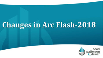
ProcessLabels are printed and placed Labels are placed in a location that is clearly visible to qualified personsbefore they begin work. The key point is that the label should be easily noticeable by workers beforethey may be exposed to any potentially dangerous live parts. NFPA 70E 130.5(D) Equipment Labeling. Electrical equipment such as switchboards,panelboards, industrial control panels, meter socket enclosures, and motor control centers that areinother than dwelling units and that are likely to require examination, adjustment, servicing, ormaintenance while energized shall be field-marked with a label containing all the followinginformation:110.4 (A)(1) Only qualified persons shall perform tasks such as testing, troubleshooting, andvoltage measuring within the limited approach boundary of energized electrical conductors or circuitparts operating at 50 volts or more or where an electrical hazard exists.130.2 (A)(3) Energized electrical conductors and circuit parts that operate at less than 50 volts shallnot be required to be de-energized where the capacity of the source and any overcurrent protectionbetween the energy source and the worker are considered and it is determined that there will be noincreased exposure to electrical burns or to explosion due to electric arcs.130.4 (D) No qualified person shall approach or take any conductive object closer to exposedenergized electrical conductors or circuit parts operating at 50 volts or more than the restrictedapproach boundary set forth in Table 130.4(D)(a) and Table 130.4(D)(b)
Label Format
Who Should Perform Your Arc Flash RiskAssessment?To PE or not to PE, that is the question The person doing the study must be“qualified”– Performed similar studies in the past– Has received training to become a“qualified” person capable of working onexposed/energized circuits– Thorough understanding of electricaldistributions systems, both design andinstallation
Arc Flash Program Common Mistakes Label calculations being entered incorrectly 100 inches becomes100 feet on label.Labels put on the wrong panelsArc Flash Assessment not being reviewed every 5 yearsEmployee TrainingUsing the NFPA Table vs. the IEEE analysisNot including Arc Flash in your change management systemNot having Arc Flash Approved fall protection
Arc Flash Program Common Mistakes Assuming a piece of equipment fed from a panel with a classificationof Zero will also have a classification of ZeroNot taking into account your maximum fault current availableArc Flash Assessment does not cover Bus below 240 Volts
Arc Flash Program Analysis Evaluation of: current arc flash labeling,Accuracy of previous arc flash hazard assessment input dataElectrical equipment conditionPersonal protective equipment (PPE)Review of electrical safety documents to verify that the principlesand procedures of the electrical safety program are in compliancewith NFPA 70E Limited interviews with electrical workers regarding field workprocedures and training
Proposed Changes to NFPA70E 2018 The layout of Article 120 Establishing an Electrically Safe Work Condition would be reorganizedto better address the logical sequence of events. LO moved to first section and verification to thelast section.A second change is to place further emphasis on the risk assessment and put the hierarchy ofcontrols into mandatory language. PPE is last method of control.The third changes clarifies how the standard should have always been used when justifiedenergized work is to be conducted. The change is that Table 130.7(C)(15)(A)(a) [that many callthe task table] has become a new table applicable to both the PPE category method or theincident energy analysis method. It no longer determines whether PPE is required but whether ornot there is a likelihood of an arc flash occurrence. The user conducts a risk assessment anddetermines the protection scheme to be employed to protect the worker using the hierarchy ofcontrols (same as in the past editions).The equipment must still meet the applicable standards but the verification process has beenchanged to one of a conformity assessment where the PPE manufacturer should be able toprovide assurance that the applicable standard has been met by one of three methods. Currentdoes not require verification.
Questions?
NFPA 70E 2015 Arc Flash Risk Assessment to determine if there is an Arc Flash Hazard If there is a hazard, employers must determine the risk to . Evaluation of: current arc flash labeling, Accuracy of previous arc flash hazard assessment input data Electrical equipment condition Personal protective equipment (PPE)