Transcription
Empowering GD&TCopyright by Multi Metrics, Inc. 2017 – All Rights ReservedIntroductionThe materials contained in this document represent an effort to clarify some of the most important concepts,tools and rules found in the ASME Y14.5 2009 Standard, as well as cast light on certain processes and bestpractices in order to help users apply GD&T more effectively and with greater ease. Mastering GD&T toapply it functionally and effectively is expensive, requiring time and dedication, but its costs are insignificantcompared to the cost of the confusion and waste caused by “bad” GD&T or “no” GD&T. Given that thedifficulty of “getting it right” often inclines users to see the acronym “GD&T” as standing for (G)rim,(D)epressing & (T)roublesome, it would seem high time to turn it into something (G)rand, (D)elightful &(T)antalizing instead. Let us hope that what follows helps.The material presented below includes no quotes from the Standard itself, but does refer to the equivalentmaterials by indicating paragraph numbers and pages where they can be found. The idea is to restate theoriginal material in ways to make it more understandable and on occasion to point out recommendedchanges to clarify and enhance the power of GD&T.1. ConceptsFully grasping the fundamental concepts of GD&T is essential in order to use it effectively. For example,failure to understand the difference between a Datum and a Datum Feature is extremely common, leadingmany users to believe that the letters which appear in the last compartments of a Feature Control Framerepresent Datums, not Datum Features, which of course is impossible, given that we can’t simulate a Datumat its Maximum Material Boundary because it has no material. Furthermore, failure to understand that aDatum Reference Frame is not a collection of Datums, but in fact a Cartesian coordinate system merelyconstrained by a set of Datums, leads to further confusion. The following paragraphs represent efforts tocome up with refined definitions of the listed concepts to hopefully enable their more effective use, andinclude references to the Y14.5 2009 Standard definitions for comparison purposes.1.11.21.31.41.51.61.71.81.91.10Basic DimensionsDatum FeaturesDatum TargetsDatum Feature SimulatorsDatumsDatum Reference FramesTolerance ZonesTolerance Zone MobilityMaterial Condition & Material Boundary ModifiersVirtual Maximum Material Boundary1.1 Basic Dimensions:Basic dimensions are fixed (invariant) angular, linear and radial dimensions extracted from 3D CAD modelswhich serve to orient and locate tolerance zones relative to one another and relative to Datum ReferenceFrames. Basic dimensions are specified in rectangular frames. Basic dimensions also serve to orient andlocate Datum Targets relative to the Datum Reference Frames they help to establish. (Y14.5 2009 §1.3.23p.3)1.2 Datum Features:1Multi Metrics, Inc. 865 Lemon Street, Menlo Park, CA 94025Tel,: 650-328-0200 – www.multimetrics.com
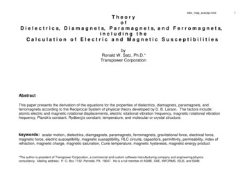
Datum Features are specially labeled, imperfect, physical surfaces of real parts which 1) serve to constrainrotational and translational degrees of freedom during assembly processes, and 2), when listed in FeatureControl Frames, represent a set of instructions for establishing Datum Reference Frames. (Y14.5 2009§1.3.16 p.3).1.3 Datum Targets:Datum Targets are limited portions of Datum Features in the form of points, lines or areas, which representthose portions of the feature which the mating Datum Feature engages during assembly. As shown in thefigure below, Datum Targets must be oriented and located by Basic dimensions relative to the DRF theydefine. Datum Targets are specified using Datum Target Labels whose lower segments contain the name ofthe target and whose upper segments remain empty in the case of point and line Datum Targets (note: butshould contain the diameter of the spherical or cylindrical simulator), and in the case of circular or squarearea Datum Targets, contain the diameter or edge length of the area simulator. Datum Targets arereferenced in Feature Control Frames using the names of their defining Datum Features. (Y14.5 2009§1.3.20 p.3 §4.24 p.83)Best Practices: Datum Targets shall always be used when a Datum Feature is only partially engaged byits mating Datum Feature. (Y14.5 2009 (§4.24 p83)1.4Datum Feature Simulators:A Datum Feature (or Datum Target) Simulator is a perfect imaginary, or almost perfect real, inverse DatumFeature representing the mating Datum Feature, which serves as a bridge from the imperfect real world ofDatum Features to the perfect imaginary world of Datum Reference Frames, and1) from which we extract Datums,2) in which we first establish Datum Reference Frames, and3) with which we transfer Datum Reference Frames to actual parts.(Y14.5 2009 §1.3.17.1 and §1.3.17.2 p.3)Notes:1) Datum Feature Simulator Behavior: The geometry and behavior of Datum Feature Simulators are2
determined 1) by the geometry of their defining Datum Features, 2) by the controls imposed on theirdefining Datum Features, 3) by their associated Material Boundary modifiers (S), (M) or (L), and 4) by“The Rules of Datum Feature Simulator Management”.Examples: 1) The Material Boundary modifier (S) requires the Datum Feature Simulator to expand orcontract toward the in-space surface of the associated Datum Feature and achieve stability relative toit. 2. The modifier (M) requires the Simulator to be fixed in size at the Virtual Maximum MaterialBoundary of the defining Datum Feature in order to permit taking advantage of potential residual “inspace” play between mating parts. 3. The modifier (L) requires the Simulator to be fixed in size at theVirtual Least Material Boundary of the defining Datum Feature to permit taking advantage of potentialresidual material in a machining operation. See the entry “Rules of Datum Feature SimulatorManagement” on p. 10 for more details.2) Examples of Real Datum Feature Simulators 1) the Datum Reference Frame establishingcomponents of a “hard gage”, and 2) the part constraining features of a “manufacturing fixture”.For further insights into Datum Features, Datum Feature Simulators and Datums, see the following table.See also “The Rules of Datum Feature Simulator Management” (p.10) “The Rules of Natural DatumReference Frame Establishment” (p.9), the “Feature Control Frame Decoding Process” (p.15) and “TheDatum Reference Frame Establishment Process” illustration (p.16).1.5Datums:Datums are the minimum, mutually embedded set of a single, perfect imaginary point, and/or straight line(axis), and/or plane, which together fully characterize the orientation and location of a Datum FeatureSimulator, or the orientation and location constraining impact of a Datum Target Simulator. Datums serve toimpose constraints on “starter” coordinate systems, and turn them into Datum Reference Frames. (Y14.52009 (§1.3.13 p.3) Note: There are six possible Datums:Note: For more insights into Datums, see the “Datum Reference Frame Establishment Process” illustrationat the end of the document.1.6Datum Reference Frames:A Datum Reference Frame (DRF) is a Cartesian (or cylindrical, or spherical) coordinate system constrainedby a set of Datums extracted from a set of Datum Feature Simulators, defined by a set of Datum Featureslisted in a Feature Control Frame. Datum Reference Frames serve, with the help of Basic dimensions, toorient and locate Tolerance Zones and Datum Targets. (Y14.5 2009 definition §4.1 p.48).Notes: In the absence of any Datum Feature references, the DRF and its associated tolerance zones are a“super mobile” set. In the presence of Datum Feature references which constrain between one and fivedegrees of freedom, the DRF and its associated tolerance zones are a “residually mobile” set, and in thepresence of Datum Feature references which constrain all six degrees of freedom, the DRF and itsassociated tolerance zones are stable, except in the presence of the Material Boundary modifiers (M) or (L),when they are again residually mobile.Notes:1) Datum Feature Simulator Behavior: The geometry and behavior of Datum Feature Simulators aredetermined 1) by the geometry of their defining Datum Features, 2) by the controls imposed on theirdefining Datum Features, 3) by their associated Material Boundary modifiers (S), (M) or (L), and 4) by“The Rules of Datum Feature Simulator Management”.3
Examples: 1) The Material Boundary modifier (S) requires the Datum Feature Simulator to expand orcontract toward the in-space surface of the associated Datum Feature and achieve stability relative toit. 2. The modifier (M) requires the Simulator to be fixed in size at the Virtual Maximum MaterialBoundary of the defining Datum Feature in order to permit taking advantage of potential residual “inspace” play between mating parts. 3. The modifier (L) requires the Simulator to be fixed in size at theVirtual Least Material Boundary of the defining Datum Feature to permit taking advantage of potentialresidual material in a machining operation. See the entry “Rules of Datum Feature SimulatorManagement” on p. 10 for more details.2) Examples of Real Datum Feature Simulators 1) the Datum Reference Frame establishingcomponents of a “hard gage”, and 2) the part constraining features of a “manufacturing fixture”.Datum Feature Simulators, Datums & Degrees FreedomFor further insights into Datum Features, Datum Feature Simulators and Datums, see the following table.See also “The Rules of Datum Feature Simulator Management” (p.10) “The Rules of Natural DatumReference Frame Establishment” (p.9), the “Feature Control Frame Decoding Process” (p.15) and “TheDatum Reference Frame Establishment Process” illustration (p.16).1.7Tolerance Zones:A tolerance zone is a perfect imaginary, bounded region of space specified by a Geometry Control Tool (Ø,Position, Surface Profile, Total Runout, Cylindricity), within which a specific component of the controlled4
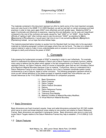
feature is required to lie. Tolerance zones are generally normal expansions of the controlled Component ofthe feature, namely 1) a tube-like zone in the case of a cylindrical surface controlled by the Diameter tool, 2)a cylindrical zone in the case of the axis of a bore controlled by the Position tool, and 3) a spherical skin-likezone in the case of a sphere controlled by the Surface Profile tool. Tolerance zones defined by locationand/or orientation constraining tools are oriented and located by Basic dimensions relative to one anotherand relative to their associated Datum Reference Fames. Tolerance zones defined by size and form toolsare orientation and location unconstrained.Examples: The tolerance zone defined by the Flatness tool is “slab-like”, by the Ø tool is “tube-like”, by theSurface Profile tool applied to a planar surface is “flat skin-like”, by the Position tool applied to a bore iscylindrical, and although not shown, by the Circular Runout tool applied to a shaft is “circular ribbon-like”,fPart Drawing and Resulting, Residually Mobile Tolerance Zones5
1.8Tolerance Zone Mobility – The Concept of Simultaneous Requirements:When mating parts are assembled they generally experience residual play, namely are free to shift slightlyrelative to one another before fasteners are tightened. It is natural for the assembly crew to take advantageof such residual play in order to hopefully make “everything fit”, but it is quite possible that a shift in onedirection will enable one feature to mate, but not another, and a shift in another direction enable the secondto mate, but no longer the first. However, if both sets of features meet their requirements “simultaneously”,all is well.Given the part shown in the illustration above, Datum Features A, B and C establish the Datum ReferenceFrame (DRF) illustrated in both figures, which is potentially residually “pitch” & “yaw” and “roll” mobile,namely “pitch” & “yaw” mobile due to the impact of the Rule of Rocking & Rolling Datum Feature Simulation(§3.3.5) and residually “roll” mobile due to the impact of the Material Boundary (Tolerance Zone Mobility)modifier (M) associated with Datum Feature C.When grouped using the nX, All Around or other grouping tools, a set of tolerance zones imposed by aGeometry Control Tool such as Position or Surface Profile makes up a local simultaneous set, namely thezones are fixed in orientation and location relative to one another regardless of their potential mobility as agroup. In the absence of fully constraining Datum Feature references, the local simultaneous set becomesresidually mobile as a group. If a collection of Feature Control Frames defining multiple local sets oftolerance zones reference the same Datum Features in the same order with the same Material Boundary(Tolerance Zone Mobility) modifiers (S), (M) or (L), but fail to fully constrain all six degrees of freedom, theydefine a residually mobile, global simultaneous set.In greater detail, under the impact of grouping tools and the Position and Surface Profile tools, Basicdimensions orient and locate individual tolerance zones relative to one another and under the impact ofDatum Features, relative to Datum Reference Frames. In the absence of any Datum Feature references, theDatum Reference Frame is “super mobile” as are the associated tolerance zones as a group. In thepresence of Datum Features which fail to constrain all six degrees of freedom, the Datum Reference Frameis “partially mobile” as are the associated tolerance zone groups. Given Datum Features which constrain allsix degrees of freedom, the Datum Reference Frame is “stable”, except in the presence of the MaterialBoundary (Tolerance Zone Mobility) modifiers (M) or (L), in which case the Datum Reference Frame and itsassociated tolerance zones are “residually mobile”. As set forth in greater detail in §1.9, the MaterialBoundary (Tolerance Zone Mobility) modifier (S) forbids the machine shop and the QA department fromtaking advantage of any potential residual mobility, the Material Boundary (To
Mastering GD&T to apply it functionally and effectively is expensive, requiring time and dedication, but its costs are insignificant compared to the cost of the confusion and waste caused by “bad” GD&T or “no” GD&T. Given that the difficulty of “getting it right” often inclines users to see the acronym “GD&T” as standing for (G)rim,