Transcription
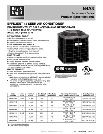
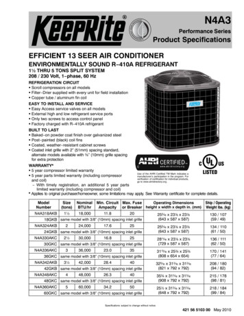
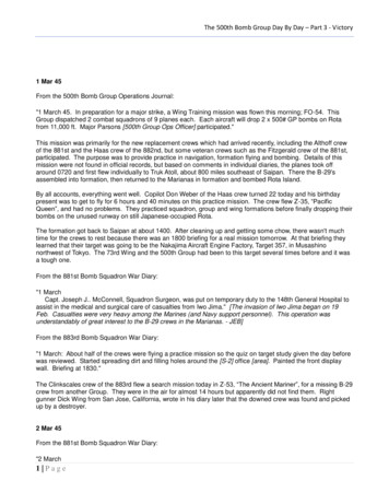
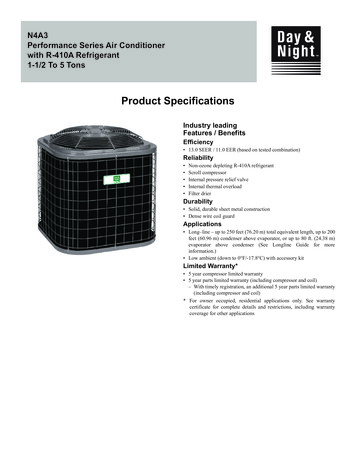
N4A3Performance Series Air Conditionerwith R-410A Refrigerant1-1/2 To 5 TonsProduct SpecificationsIndustry leadingFeatures / BenefitsEfficiency 13.0 SEER / 11.0 EER (based on tested combination)Reliability Non-ozone depleting R-410A refrigerantScroll compressorInternal pressure relief valveInternal thermal overloadFilter drierDurability Solid, durable sheet metal construction Dense wire coil guardApplications Long–line – up to 250 feet (76.20 m) total equivalent length, up to 200feet (60.96 m) condenser above evaporator, or up to 80 ft. (24.38 m)evaporator above condenser (See Longline Guide for moreinformation.) Low ambient (down to 0 F/-17.8 C) with accessory kitLimited Warranty* 5 year compressor limited warranty 5 year parts limited warranty (including compressor and coil)– With timely registration, an additional 5 year parts limited warranty(including compressor and coil)* For owner occupied, residential applications only. See warrantycertificate for complete details and restrictions, including warrantycoverage for other applications
N4A3: Product SpecificationsN4AProduct Refrigerant TypeFamily 4 R-410A A 3 13 SEER 18 1-1/2 Tons24 2 Tons30 2-1/2 Tons36 3 Tons42 3-1//2 Tons48 4 Tons60 5 TonsHVariationsA Standard Grille (Copper Tube Coil)G Dense Grille (Copper Tube Coil)B Standard Grille (Aluminum Tube Coil)L Dense Grill (Aluminum Tube Coil)BElectrical Supply SalesH 208/230-60CodeL 460-3-60S 575-3-60100Engineering ExtraRevisionDigitExtraDigit Use of the AHRI Certified Mark indicates amanufacturer’s participation in the program.For verification of certification for individual products,go to www.ahridirectory.org.QualityISO 9001CATALOG ORDERING NUMBERSThree PhaseSingle PhasePhaseSize182430364248603036424860Aluminum Coil AN/AN/AN/AN/ACopper Coil 4A360G(H,L,S)C*.Aluminum models phasing in June 2021 - February 2022. Please check with your supplier for availability.STANDARD FEATURESFeaturesR-410A RefrigerantSEER (Range depending on indoor combination)Scroll CompressorField Installed Filter DrierFront Seating Service ValvesInternal Pressure Relief ValveInternal Thermal OverloadLong Line capabilityLow Ambient capability with Kit18X24X30X36X42X48X60X13 - 1513 - 1513 - 1513 - 1513 - 14.513 - 1513 - XX StandardManufacturer reserves the right to change, at any time, specifications and designs without notice and without obligations.2
N4A3: Product SpecificationsPHYSICAL DATA 1-Phase (Copper Coil Models)UNIT SIZECompressor TypeREFRIGERANTControlFactory Chargelb 42(A,G)KNScrollR-410ATXV (Puron Hard 17(1.89)4.90(2.22)17921/121100Required Charge*lb (kg)COND FANAir DischargeAir Qty (CFM)Motor HPMotor RPMCOND COILFace Area (Sq ft)Fins per In.RowsCircuitsVALVE CONNECT. (In. ID)VaporLiquidREFRIGERANT TUBES* (In. --22181/101100Propeller Type, Direct 3/87/83/87/83/87/83/8Rated Vapor†30(A,G)KG5.36(2.48)3/4--7/8Max Liquid Line‡1-1/83/8*.For 15 ft. lineset†.Units are rated with 25 ft (7.6 m) of lineset length. See Vapor Line Sizing and Cooling Capacity Loss table when using other sizes and lengths of lineset.‡.See Liquid Line Sizing For Cooling Only Systems with R-410A Refrigerant tables.PHYSICAL DATA 3-Phase (Copper Coil Models)UNIT SIZECompressor TypeREFRIGERANTControlFactory Chargelb (kg)30GHC 36GHBRequired Charge*lb (kg)COND FANAir DischargeAir Qty (CFM)Motor HPMotor RPMCOND COILFace Area (Sq ft)Fins per In.RowsCircuitsVALVE CONNECT. (In. ID)VaporLiquidREFRIGERANT TUBES* (In. OD)Rated Vapor†‡Max Liquid Line36GLB36GSB )------48GHB 48GLBScrollR-410ATXV R-410A Hard 0029541/4110029541/4110029541/41100Propeller Type, Direct 87/87/87/87/87/87/87/83/8*.For 15 ft. lineset†.Units are rated with 25 ft (7.6 m) of lineset length. See Vapor Line Sizing and Cooling Capacity Loss table when using other sizes and lengths of lineset.‡.See Liquid Line Sizing For Cooling Only Systems with R-410A Refrigerant tables.Manufacturer reserves the right to change, at any time, specifications and designs without notice and without obligations.3
N4A3: Product SpecificationsPHYSICAL DATA (Aluminum Coil Models)UNIT SIZE-SERIESCompressor TypeREFRIGERANTControlFactory Charge lb (kg)Required Charge* lb (kg)COND FANAir DischargeAir Qty (CFM)Motor HPMotor RPMCOND COILFace Area (Sq ft)Fins per In.RowsCircuitsVALVE CONNECT. (In. ID)VaporLiquidREFRIGERANT TUBES (In. OD)18(B,L)KA24(B,L)KA2.77 (1.26)4.13 (1.87)2.77 (1.26)4.32 925133/43/43/43/43/43/4Rated (B,L)KA7.10 (3.22)7.57 (3.43)8.80 (3.99)9.31 920267/83/87/87/87/87/87/87/81-1/8TXV (Hard Shutoff)3.78 (1.71)4.11 (1.86)5.84 (2.65)5.42 (2.46)5.87 (2.66)7.02 (3.18)Propeller Type, Direct DriveVertical2250335334541/101/51/4110011001100Max Liquid Line†12.9325153/8*.Units are rated with 25 ft (7.6 m) of lineset length. See Vapor Line Sizing and Cooling Capacity Loss table when using other sizes and lengths of lineset.†.See Liquid Line Sizing For Cooling Only Systems with R-410A Refrigerant tables.OUTDOOR UNIT CONNECTED TO A FACTORY APPROVED INDOOR UNITCheck piston size shipped with indoor unit to see if it matches required indoor piston size. If it does not match, replace indoor piston with correctpiston size in table below:OUTDOOR UNIT SIZE - SERIES18243030 (3-phase)3636 (3-phase)424848 (3-phase)FAN P*FEM4P*PISTON SIZE BY OUTDOOR MODEL495561596767737876* Ratings contained in this document are subject to change at any time. Always refer to the AHRI directory (www.ahridirectory.org) for the most up-to-date ratings information.NOTE: Pistons shipped with outdoor units are only qualified and approved with the above listed fan coils. The piston included with the FFMANP* and FPMAN*fan coils are unique to those products and CANNOT be replaced with the piston shipped with outdoor unit. Refer to the AHRI directory(www.ahridirectory.org) to check if your combination can use a piston or requires an accessory TXVManufacturer reserves the right to change, at any time, specifications and designs without notice and without obligations.4
N4A3: Product SpecificationsLiquid Line Sizing and Maximum Total Equivalent Lengths for Cooling Only Systems with R-410ARefrigerant:The maximum allowable length of a residential split system depends on the liquid line diameter and vertical separation between indoor and outdoorunits.See table below for liquid line sizing and maximum lengths :Maximum Total Equivalent LengthOutdoor Unit BELOW Indoor UnitSizeLiquidLiquid LineLine Diam.Connectionw/ 163/81/45/163/81/45/163/85/163//85/163/83/83/8AC with R-410A Refrigerant Maximum Total Equivalent Length{: Outdoor unit BELOW IndoorVertical Separation ft 5)(1.8-3.0)(3.4-6.1)(6.4-9.1)(9.4-12.2) (12.5-15.2) (15.5-18.3) (18.6-21.3) 250*230160-250*250*250*225*190150110---* Maximum actual length not to exceed 200 ft (61 m){Total equivalent length accounts for losses due to elbows or fitting. See the Long Line Guideline for details.“--” outside acceptable rangeMaximum Total Equivalent LengthOutdoor Unit ABOVE Indoor UnitSizeLiquidLiquid LineLine Diam.Connectionw/ 163/81/45/163/81/45/163/85/163/85/163/83/83/8AC with R-410A Refrigerant Maximum Total Equivalent Length{: Outdoor unit ABOVE IndoorVertical Separation ft 0*250*250*250*250*250*250*250** Maximum actual length not to exceed 200 ft (61 m){Total equivalent length accounts for losses due to elbows or fitting. See the Long Line Guideline for details.“--” outside acceptable rangeManufacturer reserves the right to change, at any time, specifications and designs without notice and without obligations.5
N4A3: Product SpecificationsRefrigerant Charge AdjustmentsLiquid Line SizeR-410A Charge oz/ft (g/m)0.60 (17.74)(Factory charge for lineset 9 oz / 266.16 g)0.40 (11.83)0.27 (7.98)3/85/161/4Units are factory charged for 15 ft (4.6 m) of 3/8” liquid line*. The factory charge for 3/8” lineset 9 oz. When using other length or diameter liquidlines, charge adjustments are required per the chart above.Charging Formula:[(Lineset oz/ft x total length) – (factory charge for lineset)] charge adjustmentExample 1: System has 15 ft of line set* using existing 1/4“ liquid line. What charge adjustment is required?Formula: (.27 oz/ft x 15ft) – (9 oz) ( 4.95) oz.Net result is to remove 4.95 oz of refrigerant from the systemExample 2: System has 45 ft of existing 5/16” liquid line. What is the charge adjustment?Formula: (.40 oz/ft. x 45ft) – (9 oz.) 9 oz.Net result is to add 9 oz of refrigerant to the systemNOTE: Conditions must be favorable for charging by subcooling method. Indoor temperature must be 70 F to 80 F (21.1 C to 26.7 C), and outdoortemperature must be 70 F to 100 F (21.1 C to 37.8 C). If outside these conditions, adjust charge for long line sets by weigh-in method.* When applicable. Refer to Physical Data Table in this PD and to the Installation Instructions for more information.LONG LINE APPLICATIONSAn application is considered Long Line, when the refrigerant level in the system requires the use of accessories to maintain acceptable refrigerantmanagement for systems reliability. See Accessory Usage Guideline table for required accessories. Defining a system as long line depends on theliquid line diameter, actual length of the tubing, and vertical separation between the indoor and outdoor units.For Air Conditioner systems, the chart below shows when an application is considered Long Line.AC with R-410A Refrigerant Long Line Description ft (m) Beyond these lengths, a TXV is requiredTotal LengthTXV required beyond 50 ft. (15.2 m)Outdoor Unit Above or Below Indoor UnitTXV required beyond 20 ft. (6.1 m)AC with R-410A Refrigerant Long Line Description ft (m) (Beyond these lengths, long line accessories are required)Liquid Line Size1/4 TXV5/16 TXV3/8 TXVUnits On Same LevelNo accessories needed within allowedlengths120 (36.6)80 (24.4)Outdoor Below IndoorNo accessories needed withinallowed lengths50 (15.2) vertical or 120 (36.6) total35 (10.7) vertical or 80 (24.4) totalOutdoor Above Indoor175 (53.3)120 (36.6)80 (24.4)Note: See Residential Piping and Long Line Guideline for detailsVAPOR LINE SIZING AND COOLING CAPACITY LOSSAcceptable vapor line diameters provide adequate oil return to the compressor while avoiding excessive capacity loss. The suction line diametersshown in the chart below are acceptable for AC systems with R-410Arefrigerant:Vapor Line Sizing and Cooling Capacity Losses — 1-Stage Air Conditioner with R-410A Refrigerant ApplicationsMaximumUnitLiquid LineNominalDiametersSize (Btuh)(In. OD)0183/80243/80303/80363/80423/80483/80603/8Vapor LineDiameters(In. OD)1/25/83/45/83/47/85/83/47/85/83/47/83/47/81 1/83/47/81 1/83/47/81 1/8Cooling Capacity Loss (%)Total Equivalent Line Length ft. -225226-250(7.9-15.2) (15.5-24.4) (24.7-30.5) (30.8-38.1) (38.4-45.7) (46.0-53.3) (53.6-61.0) (61.3-68.6) 2052094193152172110425206311051Applications in this area may be long line and may have height restrictions. See the Residential Piping and Long Line Guideline.Manufacturer reserves the right to change, at any time, specifications and designs without notice and without obligations.6113152183112426307311151
N4A3: Product SpecificationsACCESSORIES (For Copper Coil Models)Part EB40601TXNAEB40701TXDescriptionCrankcase Heater for Scroll Compressor (208/230V)Crankcase Heater for Scroll Compressor (208/230V)Hard Start Kit (Capacitor & Relay)Evaporator Freeze ThermostatLow Pressure Switch, AC, R 410AHigh Pressure Switch, AC or HP, R 410ALiquid Line Solenoid Valve, R 410ATime Delay Relay, Indoor BlowerWinter Start ControlAnti Cycle Timer (5 minute delay)Low Ambient Kit (Pressure Switch), R 410ASupport Feet, 4” (102mm) tall (5 blocks)Sound Jacket, CompressorSound Jacket, CompressorSound Jacket, CompressorTXV Kit, R 410A for use with copper or tin fan coilsTXV Kit, R 410A for use with copper or tin fan coilsTXV Kit, R 410A for use with copper or tin fan coilsTXV Kit, R 410A for use with aluminum coilsTXV Kit, R 410A for use with aluminum coilsTXV Kit, R 410A for use with aluminum coilsUsed On Model Size18, 24, 30, 3642, 48, 60ALLALLALLALLALLALLALLALLALLALL18, 24, 363042, 48, 6018, 2430, 36, 4248, 6018, 2430, 36, 4248, 60ACCESSORIES (for Aluminum Coil Models)KIT EB40701TXNASA00201SJNASA00301SJNASA00101SJKIT NAMEFRZ THERM KITTIME DELAY KITLOW AMBIENT KITHARD START KITHARD START KITCYCLE PROTR KITSPRT FEET KITPTC KITSOL VALVE KITWINTER ST KITPRESSURE SW KITPRESSURE SW KITCRKC HTR KITCRKC HTR KITTXV KIT (for use with copper coils)TXV KIT (for use with copper coils)TXV KIT (for use with copper coils)TXV KIT (for use with aluminum coils)TXV KIT (for use with aluminum coils)TXV KIT (for use with aluminum coils)SOUND BLKT KITSOUND BLKT KITSOUND BLKT KITUsed on Model SizeALLALLALL18 - 4860ALLALLALLALLALLALLALL18, 24, 30, 3642, 48, 6018, 24, 3036, 4248, 6018, 24, 3036, 4248, 6018, 2430, 3642, 48, 60* Do not use Hard Shutoff TXV with Liquid Solenoid ValveManufacturer reserves the right to change, at any time, specifications and designs without notice and without obligations.7
N4A3: Product SpecificationsACCESSORY USAGE GUIDELINEACCESSORYBall Bearing Fan MotorCompressor Start Assist Capacitor and RelayCrankcase HeaterEvaporator Freeze ThermostatHard Shut-Off TXVLiquid Line Solenoid ValveLow-ambient Pressure SwitchSupport FeetWinter Start ControlREQUIRED FORLOW-AMBIENT COOLINGAPPLICATIONS(Below 55 F/12.8 C)Standard on single-phasemodelsYesYesYesYesNoYesRecommendedYes #REQUIRED FOR LONG LINEAPPLICATIONS*Standard on single-phasemodelsYesYesNoYesNoNoNoNoREQUIRED FORSEA COASTAPPLICATIONS(Within 2 miles/3.22 km)Standard on single-phasemodelsNoNoNoYesNoNoRecommendedNo*For tubing set lengths between 80 and 200 ft. (24.38 and 60.96 m) horizontal or 35 ft. ((10.7 m) vertical differential (total equivalent length), refer to the Residential Split-System LonglineApplication Guideline.#Required if Low Pressure Switch is factory or field installed.Accessory Description and Usage (Listed Alphabetically)1. Ball-Bearing Fan MotorA fan motor with ball bearings which permits speed reduction whilemaintaining bearing lubrication.Usage Guideline:Required on all units when MotorMasterr is used.2. Compressor Start Assist - Capacitor and RelayStart capacitor and relay gives a ”hard” boost to compressor motor ateach start up.Usage Guideline:Required for reciprocating compressors in thefollowing applications:Long lineLow ambient coolingHard shut off expansion valve on indoor coilLiquid line solenoid on indoor coilRequired for single-phase scroll compressors in the followingapplications:Long lineLow ambient coolingSuggested for all compressors in areas with a history of lowvoltageproblems.3. Crankcase HeaterAn electric resistance heater which mounts to the base of the compressorto keep the lubricant warm during off cycles. Improves compressorlubrication on restart and minimizes the chance of liquid slugging.Usage Guideline:Required in low ambient cooling applications.Required in long line applications.Suggested in all commercial applications.4. Cycle ProtectorThe cycle protector is designed to prevent compressor short cycling.This control provides an approximate 5-minute delay after power to thecompressor has been interrupted for any reason, including power outage,protector control trip, thermostat jiggling, or normal cycling.6. Low-Ambient Pressure Switch KitA long life pressure switch which is mounted to outdoor unit servicevalve. It is designed to cycle the outdoor fan motor in order to maintainhead pressure within normal operating limits (approximately 100 psig to225 psig). The control will maintain working head pressure atlow-ambient temperatures down to 0 F (-18 C) when properly installed.Usage Guideline:A Low-Ambient Pressure Switch must be used when coolingoperation is used at outdoor temperatures below 55 F (12.8 C). Outdoor Air Temperature SensorThis device enables the thermostat to display the outdoor temperature.This device is also required to enable special thermostat features such asauxiliary heat lock out.Usage Guideline:Suggested for use with compatible thermostats. Sound HoodWraparound sound reducing cover for the compressor. Reduces thesound level of the compressor.Usage Guideline:Suggested when unit is installed closer than 15 ft (4.57 m) to quietareas, bedrooms, etc.Suggested when unit is installed between two houses less than 10 ft(3.05 m) apart. Support FeetFour or five stick-on plastic feet that raise the unit 4 in. (101.6 mm)above the mounting pad. This allows sand, dirt, and other debris to beflushed from the unit base, minimizing corrosion.Usage Guideline:Suggested in the following applications:Coastal installations.Windy areas or where debris is normally circulating.Rooftop installations.For improved sound ratings.5. Evaporator Freeze ThermostatAn SPST temperature-actuated switch that stops unit operation whenevaporator reaches freeze-up conditions.Usage Guideline:Required when low ambient kit has been added.Manufacturer reserves the right to change, at any time, specifications an
N4A3 Performance Series Air Conditioner with R-410A Refrigerant 1-1/2 To 5 Tons. N4A3: Product Specifications Manufacturer reserves the right to change, at any time, specifications and designs without notice and without obligations. 2 X Standard N 4 A 3 18 A H B