Transcription
Accepted ManuscriptFull length articleReview of shock wave detection method in CFD post-processingZiniu Wu, Yizhe Xu, Wenbin Wang, Ruifeng .doi.org/10.1016/j.cja.2013.05.001CJA 121To appear in:Received Date:Revised Date:Accepted Date:18 January 201320 February 201318 March 2013Please cite this article as: Z. Wu, Y. Xu, W. Wang, R. Hu, Review of shock wave detection method in CFD postprocessing, (2013), doi: http://dx.doi.org/10.1016/j.cja.2013.05.001This is a PDF file of an unedited manuscript that has been accepted for publication. As a service to our customerswe are providing this early version of the manuscript. The manuscript will undergo copyediting, typesetting, andreview of the resulting proof before it is published in its final form. Please note that during the production processerrors may be discovered which could affect the content, and all legal disclaimers that apply to the journal pertain.
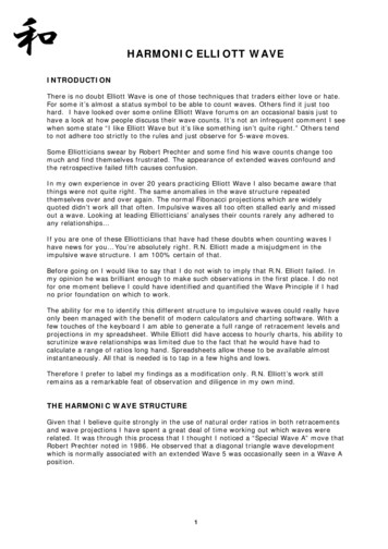
Review of shock wave detection method in CFD post-processingWU Ziniu*, XU Yizhe, WANG Wenbin, HU RuifengSchool of Aerospace, Tsinghua University, Beijing 100084, ChinaReceived 18 January 2013; revised 20 February 2013; accepted 18 March 2013AbstractIn the present computational fluid dynamics (CFD) community, post-processing is regarded as a procedure to view parameterdistribution, detect characteristic structure and reveal physical mechanism of fluid flow based on computational or experimentalresults. Field plots by contours, iso-surfaces, streamlines, vectors and others are traditional post-processing techniques. While theshock wave, as one important and critical flow structure in many aerodynamic problems, can hardly be detected or distinguishedin a direct way using these traditional methods, due to possible confusions with other similar discontinuous flow structures likeslip line, contact discontinuity, etc. Therefore, method for automatic detection of shock wave in post-processing is of great importance for both academic research and engineering applications. In this paper, the current status of methodologies developedfor shock wave detection and implementations in post-processing platform are reviewed, as well as discussions on advantagesand limitations of the existing methods and proposals for further studies of shock wave detection method. We also develop anadvanced post-processing software, with improved shock detection.Keywords: Aerodynamics; Automatic detection; Computational fluid dynamics; Shock wave; Post-processing1. IntroductionShock wave is important in aerodynamics. From a physical point of view, shock wave is a curved or plane discontinuous flow structure. In practical applications, shock wave can be beneficial or not. On the one hand, shockwave may be harmful. For high subsonic or low supersonic flight, the shock wave can give rise to large wave dragwhich acts adverse effect on aircraft performance[1]. For hypersonic flight, once the shock impinges on a body surface, strong boundary layer separation and severe peak heating[2-3] can be induced which is harmful to vehiclestructure. On the other hand, shock wave may be favorable. For example, shock wave is used for increasing pressure for an airbreathing scramjet engine and generating lift through the wave rider configuration.Due to the significant importance of the shock wave, there is an increasing demand for detection of shock wavesfrom measured or computed fluid flow results. Traditional manipulations of flow solutions, like plotting contour,iso-surface, streamlines or vectors, cannot detect the shock wave accurately and directly. Methods developed forautomatic detection of shock wave in post-processing are thus of great importance for both academic research andengineering applications[4-26].In this paper, we give a review on the current status of methods developed for shock wave detection and implementations in post-processing platform. In Section 2, the shock wave phenomenon, importance of shock waves,basic shock relations and special shock properties are briefly discussed. The existing methods for shock wave detection are classified and described with their applications in Section 3. Implementations of these methods inpost-processing softwares are presented in Section 4. Conclusion and issues needing further studies are given inSection 5.2. Shock wave in aerodynamic flows2.1. Shock wave phenomenonShock waves can be generally classified into four categories:(1) Attached shock wave, e.g. when a supersonic flow encounters an inward corner (see Fig.1(a)-(b)).(2) Detached shock wave, e.g. for a supersonic flow past a blunt body (see Fig.2(c)-(d)).(3) Recompression shock wave, generated to adjust to far field pressure, e.g. for a transonic flow past the uppersurface of an airfoil (see Fig. 2) or for a supersonic nozzle flow with high back pressure.(4) Secondary induced shock wave, due to e.g. shock reflection (see Fig. 3), shock-shock interaction (see Fig.4(a)-(b)), shock-wave/boundary-layer interaction (see Fig. 4(c)), lateral jet flow interaction (see Fig. 4(d)), etc.* Corresponding author. Tel.: 86-10-62784116.E-mail address: ziniuwu@tsinghua.edu.cn
·2 ·WU Zi-niu et al. / Chinese Journal of Aeronautics(a) Schematic of attached shock wave(b) Shock wave attached to X15 at Mach number 3.5[27](c) Schematic of detached shock wave(d) Detached bow shock around Mercury Spacecraft[28]Fig. 1 Schematic of attached shock waves and detached shock waves.(a) Schematic illustration(b) Recompression shock of a F/A-18C Hornet breaking sonic barrier[29]Fig. 2 Recompression shock waves.(a) Schematic illustration of regular reflection(b) Schematic illustration of Mach reflection
WU Zi-niu et al. / Chinese Journal of Aeronautics·3·(c) Shock waves and reflections in supersonic ramjet[30]Fig. 3Shock reflection.(a) Shock-shock interaction schematic illustration(c) Schematic of shock/boundary-layer interaction(b) Type IV shock-shock interaction[31](d) Schematic of lateral jet flow interactionFig. 4 Secondary induced shock waves.Fig.5 shows some typical examples with shock/boundary-layer interactions in the vicinity of a high-speed vehicle.Shock waves can also be generated due to explosion, combustion or lightning strike, in which local high-pressureregion may appear and lead to strong shock waves moving at supersonic speed.(a) Interactions in the vicinity of a high-speed vehicle(b) Interactions in the vicinity of a scramjetFig. 5 Examples of shock/boundary-layer interactions[32].2.2. Importance of shock wavesThe influences of shock wave on aerodynamic flow include:(1) Causing loss of total pressure, which may be a concern related to scramjet engine performance.(2) Providing lift for wave-rider configuration, as the oblique shock wave at lower surface of the vehicle can produce high pressure to generate lift.(3) Leading to wave drag of high-speed vehicle which is unbeneficial to vehicle performance. Shock wave induceddrag can be decomposed from total drag through shock wave detection[15].(4) Inducing severe pressure load and heat flux, e.g. the Type IV shock-shock interference could yield a 17 timesheating increase at vehicle surface[33-35].(5) Interacting with other structures, such as boundary layers, to produce new flow structures such as flow separation, transition, etc.
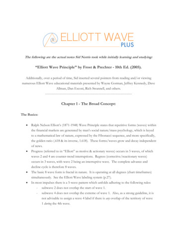
·4 ·WU Zi-niu et al. / Chinese Journal of AeronauticsTherefore, it is of significant importance to develop accurate methods for shock wave detection to capture its effects from computational solutions.2.3. Shock wave relationsFor a single oblique shock under assumption of calorically perfect gas, the pre-shock and post-shock flow parameters satisfy the well-known oblique-shock relations[1]Ma12 Ma2 2 2γ 12γMa12 sin 2 β 1γ 1 Ma12 cos 2 β f ( Ma1 , β ) (1)γ 1 2 2Ma1 sin β 12p22γ 1 ( Ma12 sin 2 β 1) g ( Ma1 , β ) (2)p1γ 1γ 1 2 2Ma1 sin βρ22 h ( Ma1 , β )ρ1 1 γ 1 Ma2 sin 2 β1(3)2where Ma is the Mach number, p the pressure, ρ the density, γ the specific heat ratio of gas, β the shockangle (equal to π / 2 for normal shock); subscript 1 and 2 indicate pre-shock and post-shock parameters respectively. Relations for other flow parameters (e.g. temperature, sonic speed, entropy) across oblique shock wave canbe found in classical textbooks for compressible gas dynamics[1].In the case of multiple shock waves with an intersection point, for example, an intersection point will occur inshock reflection and shock-shock interaction, the above shock relations (Eq. (1) to Eq. (3)) still hold across eachshock wave. But supplementary relation is also needed. Consider for instance the case of shock reflection (see Fig.6), it is well-known that regular reflection and Mach reflection are possible solutions[36]. In the case of regular reflection, two-shock structure is formed as incident shock (i) and reflected shock (r), as well as three uniform flowregions (0)-(2), as displayed in Fig. 6(a). The relations for incident shock (i) are Ma12 f ( Ma0 , β1 ) p1 / p0 g ( Ma0 , β1 ) ρ1 / ρ0 h ( Ma0 , β1 )(4)and those for reflected shock (r) are Ma22 f ( Ma1 , β 2 ) p2 / p1 g ( Ma1 , β 2 ) ρ 2 / ρ1 h ( Ma1 , β 2 )(5)The supplementary relation is a geometrical constraint that the flow after the reflected shock should be parallel tosymmetric plane,θ1 θ 2 (6)where θ is the the angle between flow and horizontal direction.By combining Eq. (4) to Eq. (6), flow parameters in regions (1) and (2) can be determined.In the case of Mach reflection, the incident shock (i), the reflected shock (r) and the Mach stem (m) form athree-shock structure, also with four uniform flow regions (0)-(3), as shown in Fig. 6(b). At the triple point (T), theshock relations Eq. (1) to Eq. (3) are applied across the incident shock (i) for weak solution, the reflected shock (r)for weak or strong solution depending on Ma2 1 or not, and the Mach stem (m) for strong solution. The pressureacross the slip line is continuous as p2 p3 . The flow deviation angles satisfy θ 3 θ1 θ 2 for standardthree-shock configuration and θ 3 θ1 θ 2 for non-standard one[36].
WU Zi-niu et al. / Chinese Journal of Aeronautics(a) Regular reflection·5·(b) Mach regular reflectionFig. 6 Schematic illustration of shock wave reflection.For shock-shock interaction, similar to shock reflection, across each shock wave the oblique shock relations Eq.(1) to Eq. (3) still hold. Also supplementary relations are needed[37].2.4. Special properties of shock waveHere we list some well-known special properties of shock waves:(1) The width of shock wave is in a magnitude of the local mean free path of fluid particles, so the shock wavecan be regarded as a sharp discontinuity in common aerodynamic flow.(2) Across shock wave streamwisely, the pressure, density, temperature and entropy all increase.(3) Across shock wave streamwisely, the Mach number, velocity and normal velocity component and totalpressure decrease.(4) Across shock wave streamwisely, total temperature and tangential velocity component remain unchangedfor calorically perfect gas.(5) Differences with other discontinuities. There exist some other discontinuities in fluid flow than the shockwave. The slip surface (3D) or slip line (2D) is a plane across which the tangent velocity is discontinuous, whilepressure and normal velocity are continuous. Across the contact discontinuity, the pressure and velocity are continuous and the density is discontinuous.(6) Concentration of contour lines. As a discontinuity in the flow field, the contour line of Mach number, pressure, density, temperature all concentrate near the shock wave (see Fig. 7). For slip plane and contact discontinuity, pressure contour lines do not concentrate.(a) Mach number contour(b) Pressure contour(c) Density contourFig. 7 Contour concentration examples at Ma 5 .(d) Temperature contour(7) Numerical solution of shock wave. In numerical solutions of fluid flow with discontinuities (shock wave,contact discontinuity or slip line) by the shock-capturing method, the shock wave can be smoothed by low-orderscheme or there are spurious oscillations near shock surface by high-order scheme[38], as shown in Fig. 8, wheresolid lines represent analytical solution, and dotted lines represent computed result. In the classical boundaryshock-fitting method[39], shock wave must be introduced explicitly as outer flow boundary, which depends onexperimental, theoretical or numerical-based knowledge on shock shape and location. While in the floatingshock-fitting method proposed by Moretti[40], shock waves are detected through Rankine-Hugoniot jump condition and the method of characteristics, which may be applicable to shock detection in post-processing.
·6 ·WU Zi-niu et al. / Chinese Journal of Aeronautics(a) Computed with first-order Godunov’s method(b) Computed with second-order two-step Lax-Wendroff method[38]Fig. 8 Solution of Sod problem for Euler equations.3. Methods for shock wave detection3.1. Difficulties for shock wave detectionDue to special properties of shock waves as discussed in Subsection 2.4, there exist several difficulties for shockdetection from CFD result:(1) The numerical dissipation and oscillation in CFD may cause some shock waves to be undetected. The numerical dissipation smears the discontinuity in the flow field, and makes weak shock waves undetectable.(2) The numerical oscillation produces structures similar to weak shock waves just near real shock wave, and thusmay lead to false detection results.(3) The similarity among shock waves and other discontinuous flow structures like slip lines can lead to incorrectdetection results.(4) The graphical display of shock detection result is also a problem for three-dimensional and multiple shockwaves.3.2. Traditional shock detection methodsTraditionally, through the contour lines one may detect shock waves since near shock waves the contour lines areconcentrated. While pressure, density, temperature and Mach number contour lines all concentrate near shock waves,only pressure contour is recommended for shock detection (see Fig. 9(a)), because the others cannot distinguishshock wave from slip line, shear layer or contact discontinuity (see Fig. 9(b)-(d)). However, it is still difficult to geta clear view of the shock wave structure from pressure contour. Also contour method cannot give a direct way todisplay shock surfaces in three-dimensional flow field. These disadvantages highly restrict the use of this contourshock detection method.
WU Zi-niu et al. / Chinese Journal of Aeronautics(a)Pressure contourFig. 9·7·(b) Mach number contour(c) Density contour(d) Temperature contour.Different contour concentrations for shock wave and shear layer at Ma 3.5 .Another traditional shock detection method is to plot the iso-surface of Mach number. It is convenient to approximate the shock surface around the vehicle by displaying a Mach number iso-surface just a little lower than thefreestream Mach number. This method can yield a full shock wave surface in three-dimensional flow field. However,it may produce too many surfaces other than desired shock wave surfaces, and become helpless to detect shockwave except the leading shock wave (see Fig. 10).Fig. 10 Iso-surface of Machnumber 8.79 of X43 at Ma 8.8 .3.3. Advanced methods for shock detectionIn recent years, several advanced shock detection methods have been developed, as classified in Table 1. In thissubsection, we will give a comprehensive description over them.
·8 ·WU Zi-niu et al. / Chinese Journal of AeronauticsTable 1 Advanced shock wave detection methodsMethodProposerDensity gradient Pagendarm andmaximaSeitz[6]FormulationIso-surface:d2 ρV V ( ρ ) 02V VdnFilter:Vdρ ρ εVdnIso-surface: Man Normal MachnumberCharacteristicsLovely andHaimes[7]Kanamori andSuzuki[10]Filter:(( p n pM p V p 1 pa p c, p p η η p maxProperty(a) Generate shock surface corresponding tothe density gradient maxima.(b) May produce false or incomplete result.(c) Need filtering.(a) Easy to implement.(b) Generate a region containing the shockwave.(c) May produce false or incomplete result.(d) Need filtering.Calculate characteristic line of))Ma2 1cosθ sin θ / Ma Ax b2Ma 1sin θ mcosθ / Ma Filter:(( Ma n )L 1) (( Ma n )R 1) 0(a) Lots of calculation effort.(b) Can yield good detection result.(c) Hard to get shock surface in 3D flowfield.3.3.1 Method based on flow property gradientShock wave is a discontinuity as a high gradient of flow properties. Pagendarm and Seitz[6] proposed a shock detection method based on searching the maxima of the density gradient. The first and second derivatives of densityare calculated in the direction of velocity.V dρ dn ρ V (7) 2 d ρ ( ρ V ) V dn 2V V dρd2 ρandare the first and second derivatives of density in the direction of velocity respectively.dndn 2The iso-surface of d 2 ρ / dn 2 0 corresponds to the maxima or minima of streamwise density gradient. dρ / dnis used as the filtering variable. Condition dρ / dn 0 corresponds to shock wave, while dρ / dn 0 correspondswhereto expansion wave. However, d 2 ρ / dn 2 0, dρ / dn 0 is also satisfied in some smooth flow regions. Then thefilter should be designed as dρ / dn ε . The filtering value ε should be large enough to remove incorrect result insmooth flow regions, and on the other hand ε should be small enough to keep weak shock waves unfiltered. Therefore, a reasonable filtering value ε is very difficult to determine. A example of shock wave detected by Pagendarm’s method is shown in Fig. 11.Fig. 11 A shock wave around an aircraft[6].
WU Zi-niu et al. / Chinese Journal of Aeronautics·9·3.3.2 Method based on normal Mach numberAs we know, a general oblique shock wave can be regarded as a normal shock wave superimposed on a uniformflow. The flow properties before and after the oblique shock wave in normal direction satisfy normal shock relations.The normal direction of shock wave is perpendicular to local pressure gradient, and thus normal Mach number canbe obtained from pressure distribution and the iso-surface of unity normal Mach number represents detected shockwave surface, which is the method of shock detection based on normal Mach number proposed by Lovely andHaimes[7].The mathematical formulation for stationary shock wave detection based on normal Mach number Man isMan Ma p V p 1 (8)a p pwhere Ma is Mach number vector in the direction of local flow velocity V , p flow parameter, a local sonicspeed.For transient shock detection, the movement of shock wave must be taken into consideration, and the conditionbecomes1 1 Dp1 1 dp Ma p 1 (9) p a Dt p a dt pwhere dp / dt is the time derivative of pressure, which can be calculated based on the spatial variation of state variables asdp γ 1 1 ( ρVH ) V ( p ρVV ) V 2 ( ρV ) (10)dt2γ where H is static enthalpy. See Lovely and Haimes[7] for the detailed derivation of Eq. (9) and Eq. (10).In practical application, the normal Mach number is calculated through velocity projection along pressure gradient direction. Due to numerical error of the interpolation scheme, small and undirected pressure gradient may becalculated in uniform flow region, leading to a random Man distribution and false shock wave detection. Filteringis a common strategy to avoid such pseudo-shock. Usually, filtering factor c and η are introduced in filteringmethod, and local pressure gradient satisfying p n c (11) p p p η pηmax is retained, in which n is the unit normal vector of detected shock surface. Examples of shock waves detected bythis method are shown in Fig. 12.(a) Stationary algorithm on converged solution (b)Transient algorithm without filtering (c) Transient algorithm with p filteringFig. 12 Shock detection result of F18 aircraft[7].However, some new problems arise with the introduction of filtering factors. If filtering factors are too small,false shock wave structures may be detected. While if filtering factors are too large, weak shock wave may be filtered out and detected one is not complete. In other words, there exists unavoidable uncertainty of the normal Machnumber based method applied to complex flows. The advantages of this method lie in simplicity of mathematicalformulation, easy understanding of physical meaning and convenience for implementation.
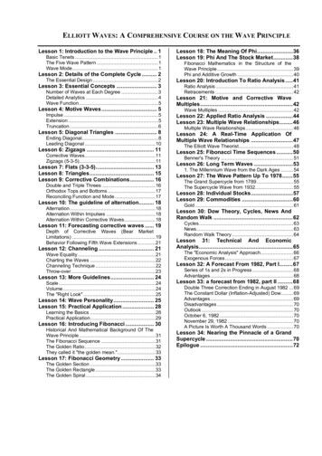
·10 ·WU Zi-niu et al. / Chinese Journal of Aeronautics3.3.3 Method based on characteristicsKanamori and Suzuki[10] proposed a shock detection method based on characteristics. Here a short description ofthis method is given for shock detection in both steady two-dimensional and three-dimensional flow.For two-dimensional flow, supersonic and subsonic regions are treated separately. Calculation procedures for supersonic region are(1) Calculate characteristic vector f ( x ) at each grid vertex(( dx f ( x) dτ ))Ma2 1cosθ sin θ / Ma (12)Ma2 1sin θ mcosθ / Ma where Ma is local Mach number, θ the angle between flow and horizontal direction.(2) Construct triangle element using three neighboring vertexes, and calculatef ( x) Ax b(13)(3) Compute characteristic line of Eq. (13), and judge whether the shock-crossing condition (equivalent to entropy condition or Lax condition) is satisfied as(( Man )L 1) (( Man )R 1) 0(14)in which vertex L is the farthest from the characteristic line, R is the symmetric point of vertex L with respect to thecharacteristic line, on which the flow properties are interpolated from other three vertexes.(4) If the Eq. (14) is satisfied, then this critical line is shock wave.Because there is no characteristic line in subsonic region, different procedures were proposed by Kanamori andSuzuki[10] as follows.(5) Calculate new velocities V1 and V2 as V1 V / 2 a V2 V / 2 a(15)where vector a is perpendicular to V and has length equal to local sound speed .(6) Calculate f ( x ) for V1 and V2 in a similar way of Eq. (12), and retain two of four obtained characteristic vectors which are in opposite direction of flow velocity V .7) Follow the same procedures of (2) to (4) in supersonic case.In three-dimensional flow, there are infinite characteristic lines at one point while only two lines are required forshock detection. Kanamori and Suzuki[10] defined plane of motion (see Fig. 13)as a local region where streamlinescan be regarded as plane curves. The characteristic vectors are obtained by the intersections between Mach cone andthe plane of motion. Characteristic vector Ci is defined asCi U cos μ α sin μ(16)where U and α denote unit vectors parallel and normal to streamline, and μ is Mach angle, as U V / V α ( dV / dτ ) / dV / dτ dV / dτ d( Ax b) / dτ A ( Ax b ) μ arcsin 1/ Ma() (17)The main procedures for shock detection in three-dimensional flow is(8) Construct triangular element through three neighboring grid vertexes, interpolate velocity linearly asV Ax b and obtain A and b .(9) Calculate characteristic vectors according to Eq. (15).(10) Construct linear interpolation of Ci and obtain critical surface.(11) If the critical surface satisfies shock-crossing condition Eq. (14), the critical surface is detected as shockwave surface.
WU Zi-niu et al. / Chinese Journal of Aeronautics· 11 ·Fig. 13 Definition of the characteristics in three-dimensional flow[10].Furthermore, Kanamori and Suzuki[11] extended their method to unsteady flow, in which pre- and post-shock regions may be subsonic if a shock is moving at supersonic speed. They simply chose a ‘shock-fixed’ coordinate moving with the shock, then the method for steady flow can be used.In Fig. 14, two-dimensional shock detection applications based on characteristics are given[10], such as supersonicflow past a sphere-cone, transonic flow around an airfoil and supersonic flow past a double wedge, showing excellent shock detection performance. In Fig. 15, three-dimensional shock wave surfaces are detected for supersonicflow past a sphere-cone and supersonic viscous flow around a delta wing[10].Fig. 14 Two-dimensional shock detection results[10].Fig. 15 Three-dimensional shock detection results[10].4. Implementation of shock wave detection methods
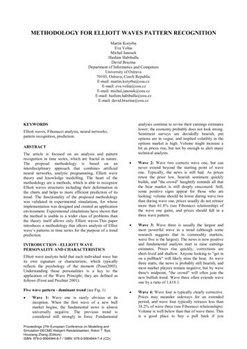
·12 ·WU Zi-niu et al. / Chinese Journal of Aeronautics4.1. Shock wave detection methods implemented in CFD post-processing softwareShock wave detection methods have been implemented in some popular commercial or open-source CFDpost-processing software, and Table 2 gives comparisons of some popular ones focusing on shock detection capabilities.Tecplot is a famous post-processing software developed by Tecplot, Inc. It has implemented normal Mach number algorithm of Lovely and Haimes[7] to detect shock structures. However, the detection result is not filtered, so itmay contain false outcomes. Users can do the filtering by calculating filter variables, pressure gradient magnitudefor example, and then apply data value blanking to shock surfaces to get a filtered result. Tecplot’s powerful scripting functions allow users to implement almost any shock detection algorithm.The powerful post-processing software EnSight implements two shock detection algorithms: one (the Surfacemethod of EnSight) is based on Pagendarm and Seitz[6] algorithm, and the other (the Region method of EnSight) isbased on Lovely and Haimes[7] algorithm. Both algorithms need threshold variables to filter the result. The algorithms guess a threshold to obtain initial results, and provide user-controllable filtering thresholds. Through command line more commands can be used to filter the flow field before/after the detection of shock waves.Table 2 Comparisons of some popular CFD post-processing softwares for shock detectionSoftwarePropertyA general post-processing tool,Tecplotwidely usedAgeneralandpowerfulEnSightpost-processing tool, complicatedto useSpecial post-processing for ANANSYS CFD-PostSYS CFX and FluentSpecial post-processing for ESIESI CFD-VIEWCFD-ACE and CFD-FASTRANAdvanced Post A post-processing tool for general(by present authors) CFD solutions, easy to useMethod for shock detection[7]FilterNormal Mach NumberNone (Can be done manually)Gradient maxima[6]Normal Mach number[7]Multiple gradient-based filtersNoneNoneNoneNoneNormal Mach number[7]Multiple filters, easy handling4.2. Applications of shock wave detectionWatanabe, et al. [14] used the shock detection method of Lovely and Haimes[7] in aerodynamic shape optimizationof a near-sonic passenger plane(see Fig.16).Fig.16 Shock profile of a near-sonic passenger plane [14].Ito, et al. [13] used the shock detection method of Lovely and Haimes[7] in mesh refining. They applied shock detection method to an initial CFD result to find the location of shock waves, and then refine the mesh near the shockwave to get a better result. They applied a least square fitting method to get estimated shock waves, however thismethod only fits shockwave with simple shape (see Fig. 17).
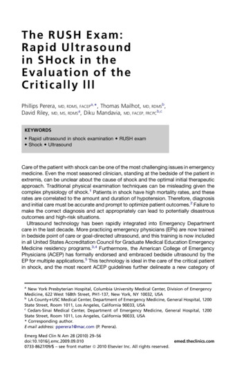
WU Zi-niu et al. / Chinese Journal of Aeronautics· 13 ·Fig. 17 Shock detection result with other structures for a capsule[13].Yamazaki, et al. [15] used the shock detection method Lovely and Haimes[7] in drag decomposition. They used thismethod to get a region surrounding the shockwave to integrate the wave drag component.4.3. A new implementation of shock wave detectionThe normal Mach number-based shock detection method[7] has been implemented in an advanced post-processingsoftware for CFD by present authors, and user interactive filter is adjustable through the interface (see Fig.18). Inthis software, we implemented two new filters which provide improved results.Fig.18User interface of shock detection in Advanced Post.The normal Mach number Man is calculated at each grid vertex. Then shock surface is generated byiso-surfaces of Man 1 , as in Fig. 19(a) and Fig. 20. Contour lines of Man 1 can also be generated on a specificplane to show shock waves sections, as in Fig. 19(b) and Fig. 21.(a) Shock surface(b) Shock on symmetry planeFig. 19 Shock detection results of a scramjet inlet at Ma 6 .Fig. 20 Shock detection result of X-43A at Ma 8.9 and α 3.6o .
·14 ·WU Zi-niu et al. / Chinese Journal of Aeronautics(a) Ma 0.8(b) Ma 0.85(c) Ma 0.9Fig. 21 Shock detection result of an NACA 0012 airfoil at α 0o .In uniform flow region, the CFD results may contain small pressure gradient due to numerical errors. As we usethe normalized pressure gradient vector in Eq.(7), it may result in a random distribution of Man as in Fig. 22(a).Thus without filtering, the shock detection may result in countless false results even in uniform flow regions (seeFig. 22(b)).Two new filtering criteria are used to filter the detected results. The first criteria remove false result related tonumerical errors and smooth flow regions. This criterion removes all shock surfaces that do not satisfy Eq. (18),where ε is a positive filtering threshold, pabsolute absolute pressure and ln the local mesh size in the p direction. Compared to the original filter p p η η p max , this filter takes account of the local mesh size andpressure, thus it can yield better result in complex flow. The filtering threshold ε should be chosen according tothe CFD solution, and we suggest an initial value of 0.001. Applying this criterion leads to reasonable shock detection result (see Fig. 22(c)). p εpabsoluteln(18)(a) Isoline of Man 1 on the symmetry plane (b) Shock detection result without filtering (c) Shock detection result with filteringof pressure gradient, ε 0.001Fig. 22 Shock detection of leading edge shockwave at Ma 6 .The second criterion is based on a simple fact that the flow velocity before the shock is larger than that behind theshock, asV V 0 (19)This filter removes the upstream part of shock region, leaving shock surface as shown in Fig. 23.
WU Zi-niu et al. / Chinese Journal of Aeronautics(a) No filtering· 15 ·(b) Filter
In the present computational fluid dynamics (CFD) community, post-processing is regarded as a procedure to view parameter distribution, detect characteristic structure and reveal physical mechanism of fluid flow based on computational or experimental