Transcription
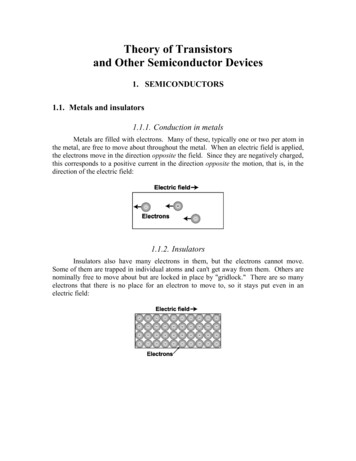
RCX200N20DatasheetNch 200V 20A Power MOSFET OutlineVDSS200VRDS(on) (Max.)130m ID20APD48W FeaturesTO-220FM(1) (2)(3) Inner circuit1) Low on-resistance.2) Fast switching speed.(1) Gate(2) Drain(3) Source 13) Drive circuits can be simple.4) Parallel use is easy.(1)(2) 1 BODY DIODE(3)5) Pb-free lead plating ; RoHS compliant6) 100% Avalanche tested Packaging specificationsPackaging ApplicationSwitching Power SupplyTypeBulkReel size (mm)-Tape width (mm)-Automotive Motor DriveQuantity (pcs)Automotive Solenoid DriveTaping code500-MarkingRCX200N20 Absolute maximum ratings(Ta 25 C)ParameterSymbolValueUnitVDSS200VTc 25 CID *1 20ATc 100 CID *1 10.8A 80ADrain - Source voltageContinuous drain currentPulsed drain currentID,pulse*2Gate - Source voltageVGSS 30VAvalanche energy, single pulseEAS *332.3mJAvalanche currentIAR *310ATc 25 CPD48WTa 25 CPD2.23WTj150 CTstg 55 to 150 CPower dissipationJunction temperatureRange of storage temperaturewww.rohm.com 2015 ROHM Co., Ltd. All rights reserved.1/122019.05 - Rev.C
Data SheetRCX200N20 Thermal rmal resistance, junction - caseRthJC--2.57 C/WThermal resistance, junction - ambientRthJA--56 C/WSoldering temperature, wavesoldering for 10sTsold--265 C Electrical characteristics(Ta 25 C)ValuesParameterDrain - Source breakdown voltageSymbolV(BR)DSSUnitConditionsVGS 0V, ID 1mAMin.Typ.Max.200----25VVDS 200V, VGS 0VZero gate voltage drain currentIDSSTj 25 C AVDS 200V, VGS 0V--100Tj 125 CGate - Source leakage currentGate threshold voltageStatic drain - sourceon - state resistanceIGSSVGS 30V, VDS 0V-- 100nAVGS (th)VDS 10V, ID 1mA3.0-5.0VVGS 10V, ID 10A-100130-2203104.99.8-RDS(on) *4 VGS 10V, ID 10Am Tj 125 CForward transfer admittancewww.rohm.com 2015 ROHM Co., Ltd. All rights reserved.gfsVDS 10V, ID 10A2/12S2019.05 - Rev.C
Data SheetRCX200N20 Electrical characteristics(Ta 25 nput capacitanceCissVGS 0V-1900-Output capacitanceCossVDS 25V-120-Reverse transfer capacitanceCrssf 1MHz-70-VDD 100V, VGS 10V-35-ID 10A-100-RL 10 -60-RG 10 -45-Turn - on delay time*4td(on)tr *4Rise timeTurn - off delay timeFall time*4td(off)tf*4pFns Gate Charge characteristics(Ta 25 C)ValuesParameterSymbol*4Total gate chargeQgGate - Source chargeQgs *4Gate - Drain chargeQgdGate plateau voltage*4V(plateau)ConditionsUnitMin.Typ.Max.VDD 100V-40-ID 10A-15-VGS 10V-15-VDD 100V, ID 10A-8.0-nCV Body diode electrical characteristics (Source-Drain)(Ta 25 C)ValuesParameterContinuous source currentSymbolConditionsTyp.Max.--20A--80AVGS 0V, IS 20A--1.5VIS 10Adi/dt 100A/ s-100-ns-350-nC*1ISPulsed source currentISM*2Forward voltageVSD*4*4Reverse recovery timetrrReverse recovery chargeQrr*4UnitMin.Tc 25 C*1 Limited only by maximum temperature allowed.*2 Pw 10 s, Duty cycle 1%*3 L 500 H, VDD 50V, Rg 25 , starting Tj 25 C*4 Pulsedwww.rohm.com 2015 ROHM Co., Ltd. All rights reserved.3/122019.05 - Rev.C
Data SheetRCX200N20 Electrical characteristic curvesFig.2 Maximum Safe Operating AreaFig.1 Power Dissipation Derating Curve1000Ta 25ºCSingle Pulse100100PW 100 sDrain Current : ID [A]Power Dissipation : PD/PD max. [%]12080604020010PW 1msOperation in thisarea is limitedby RDS(on)10.1PW 10ms0.0102550751001251500.11751101001000Drain - Source Voltage : VDS [V]Junction Temperature : Tj [ C]Normalized Transient Thermal Resistance : r(t)Fig.3 Normalized Transient ThermalResistance vs. Pulse Width10Ta 25ºCSingle PulseRth(j-c)(t) r(t) Rth(ch-c)Rth(j-c) 56ºC/W10.10.010.0001top D 1D 0.5D 0.1D 0.05D 0.01D Single0.011100Pulse Width : PW [s]www.rohm.com 2015 ROHM Co., Ltd. All rights reserved.4/122019.05 - Rev.C
Data SheetRCX200N20 Electrical characteristic curvesFig.5 Avalanche Energy Derating Curvevs Junction TemperatureFig.4 Avalanche Current vs Inductive Load120VDD 50V,RG 25 VGF 10V,VGR 0VStarting Tch 25ºCAvalanche Energy : EAS / EAS max. [%]Avalanche Current : IAS [A]1001010.10.010.11101008060402000100Coil Inductance : L [mH]5075100125150175Junction Temperature : Tj [ C]Fig.7 Typical Output Characteristics(II)Fig.6 Typical Output Characteristics(I)205Ta 25ºCPulsed4.5VGS 10.0VDrain Current : ID [A]3.53VGS 6.5V21.5VGS 6.0V1VGS 5.5V0.5VGS 8.0VTa 25ºCPulsed16VGS 7.0V2.5VGS 10.0V18VGS 8.0V4Drain Current : ID [A]2514VGS 7.0V12108VGS 6.5V6VGS 6.0V4VGS 5.5V20000.20.40.60.80146810Drain - Source Voltage : VDS [V]Drain - Source Voltage : VDS [V]www.rohm.com 2015 ROHM Co., Ltd. All rights reserved.25/122019.05 - Rev.C
Data SheetRCX200N20 Electrical characteristic curvesFig.9 Typical Transfer Characteristics100280VGS 0VID 1mA270VDS 10V10260250Drain Current : ID [A]Normarize Drain - Source Breakdown Voltage: V(BR)DSS [V]Fig.8 Breakdown Voltagevs. Junction Temperature2402302202102001Ta 125ºCTa 75ºCTa 25ºCTa 25ºC0.10.011900.001180-5005010001501Junction Temperature : Tj [ C]345678910Gate - Source Voltage : VGS [V]Fig.10 Gate Threshold Voltagevs. Junction TemperatureFig.11 Transconductance vs. Drain Current5.0100VDS 10VVDS 10VID 1mA4.5Transconductance : gfs [S]Gate Threshold Voltage : VGS(th) [V]24.03.53.02.5-50 -25025507510.10.010.01100 125 150Junction Temperature : Tj [ C]www.rohm.com 2015 ROHM Co., Ltd. All rights reserved.10Ta 25ºCTa 25ºCTa 75ºCTa 125ºC0.1110100Drain Current : ID [A]6/122019.05 - Rev.C
Data SheetRCX200N20 Electrical characteristic curvesFig.12 Static Drain - Source On - StateResistance vs. Gate Source Voltage1000Ta 25ºC250ID 10A200ID 20A15010050005101520Static Drain - Source On-State Resistance: RDS(on) [m ]300Static Drain - Source On-State Resistance: RDS(on) [m ]Fig.13 Static Drain - Source On - StateResistance vs. Drain Current(I)Gate - Source Voltage : VGS [V]Ta 25ºCVGS 10V100100.010.1110100Drain Current : ID [A]Fig.14 Static Drain - Source On - StateResistance vs. Junction TemperatureStatic Drain - Source On-State Resistance: RDS(on) [m ]300VGS 10VID 10A250200150100500-50050100150Junction Temperature : Tj [ºC]www.rohm.com 2015 ROHM Co., Ltd. All rights reserved.7/122019.05 - Rev.C
Data SheetRCX200N20 Electrical characteristic curvesFig.15 Static Drain - Source On - StateResistance vs. Drain Current(II)Fig.16 Drain Current Derating Curve120VGS 10V100Drain Current Dissipation: ID/ID max. (%)Static Drain - Source On-State Resistance: RDS(on) [m ]10000Ta 125ºCTa 75ºCTa 25ºCTa 25ºC1000100806040200100.010.11100100Drain Current : ID [A]www.rohm.com 2015 ROHM Co., Ltd. All rights reserved.255075100125150175Junction Temperature : Tj [ C]8/122019.05 - Rev.C
Data SheetRCX200N20 Electrical characteristic curvesFig.17 Typical Capacitancevs. Drain - Source VoltageFig.18 Switching Characteristics1000010000Cisstf1000Switching Time : t [ns]1000Capacitance : C [pF]Ta 25ºCVDD 100VVGS 10VRG 10 Coss100Crss10Ta 25ºCf 1MHzVGS 0Vtd(off)100td(on)10tr110.010.11101000.011000Drain - Source Voltage : VDS [V]0.1110100Drain Current : ID [A]Fig.19 Dynamic Input CharacteristicsGate - Source Voltage : VGS [V]20Ta 25ºCVDD 100VID 10ARG 10 15105001020304050607080Total Gate Charge : Qg [nC]www.rohm.com 2015 ROHM Co., Ltd. All rights reserved.9/122019.05 - Rev.C
Data SheetRCX200N20 Electrical characteristic curvesFig.20 Source Currentvs. Source - Drain VoltageFig21 Reverse Recovery Timevs.Source Current1001000Source Current : IS [A]10Reverse Recovery Time : trr [ns]VGS 0VTa 125ºCTa 75ºCTa 25ºCTa 25ºC10.1Ta 25ºCdi / dt 100A / sVGS 0V100100.010.00.51.00.11.5Source-Drain Voltage : VSD [V]www.rohm.com 2015 ROHM Co., Ltd. All rights reserved.110100Source Current : IS [A]10/122019.05 - Rev.C
Data SheetRCX200N20 Measurement circuitsFig.1-1 Switching Time Measurement CircuitVGSFig.1-2 Switching WaveformsPulse td(on)tonFig.2-1 Gate Charge Measurement CircuitVGStftoffFig.2-2 Gate Charge QgsVDDQgdChargeFig.3-1 Avalanche Measurement CircuitVGSIASD.U.T.RGFig.3-2 Avalanche WaveformVDSLV(BR)DSSIASVDDVDDEAS www.rohm.com 2015 ROHM Co., Ltd. All rights reserved.11/12122L IASV(BR)DSSV(BR)DSS - VDD2019.05 - Rev.C
Data SheetRCX200N20 Dimensions (Unit : .1340.1220.015Dimension in mm/incheswww.rohm.com 2015 ROHM Co., Ltd. All rights reserved.12/122019.05 - Rev.C
NoticePrecaution on using ROHM Products1.Our Products are designed and manufactured for application in ordinary electronic equipment (such as AV equipment,OA equipment, telecommunication equipment, home electronic appliances, amusement equipment, etc.). If youintend to use our Products in devices requiring extremely high reliability (such as medical equipment (Note 1), transportequipment, traffic equipment, aircraft/spacecraft, nuclear power controllers, fuel controllers, car equipment including caraccessories, safety devices, etc.) and whose malfunction or failure may cause loss of human life, bodily injury orserious damage to property (“Specific Applications”), please consult with the ROHM sales representative in advance.Unless otherwise agreed in writing by ROHM in advance, ROHM shall not be in any way responsible or liable for anydamages, expenses or losses incurred by you or third parties arising from the use of any ROHM’s Products for SpecificApplications.(Note1) Medical Equipment Classification of the Specific ��CLASSⅢCLASSⅣCLASSⅢ2.ROHM designs and manufactures its Products subject to strict quality control system. However, semiconductorproducts can fail or malfunction at a certain rate. Please be sure to implement, at your own responsibilities, adequatesafety measures including but not limited to fail-safe design against the physical injury, damage to any property, whicha failure or malfunction of our Products may cause. The following are examples of safety measures:[a] Installation of protection circuits or other protective devices to improve system safety[b] Installation of redundant circuits to reduce the impact of single or multiple circuit failure3.Our Products are designed and manufactured for use under standard conditions and not under any special orextraordinary environments or conditions, as exemplified below. Accordingly, ROHM shall not be in any wayresponsible or liable for any damages, expenses or losses arising from the use of any ROHM’s Products under anyspecial or extraordinary environments or conditions. If you intend to use our Products under any special orextraordinary environments or conditions (as exemplified below), your independent verification and confirmation ofproduct performance, reliability, etc, prior to use, must be necessary:[a] Use of our Products in any types of liquid, including water, oils, chemicals, and organic solvents[b] Use of our Products outdoors or in places where the Products are exposed to direct sunlight or dust[c] Use of our Products in places where the Products are exposed to sea wind or corrosive gases, including Cl2,H2S, NH3, SO2, and NO2[d] Use of our Products in places where the Products are exposed to static electricity or electromagnetic waves[e] Use of our Products in proximity to heat-producing components, plastic cords, or other flammable items[f] Sealing or coating our Products with resin or other coating materials[g] Use of our Products without cleaning residue of flux (Exclude cases where no-clean type fluxes is used.However, recommend sufficiently about the residue.) ; or Washing our Products by using water or water-solublecleaning agents for cleaning residue after soldering[h] Use of the Products in places subject to dew condensation4.The Products are not subject to radiation-proof design.5.Please verify and confirm characteristics of the final or mounted products in using the Products.6.In particular, if a transient load (a large amount of load applied in a short period of time, such as pulse, is applied,confirmation of performance characteristics after on-board mounting is strongly recommended. Avoid applying powerexceeding normal rated power; exceeding the power rating under steady-state loading condition may negatively affectproduct performance and reliability.7.De-rate Power Dissipation depending on ambient temperature. When used in sealed area, confirm that it is the use inthe range that does not exceed the maximum junction temperature.8.Confirm that operation temperature is within the specified range described in the product specification.9.ROHM shall not be in any way responsible or liable for failure induced under deviant condition from what is defined inthis document.Precaution for Mounting / Circuit board design1.When a highly active halogenous (chlorine, bromine, etc.) flux is used, the residue of flux may negatively affect productperformance and reliability.2.In principle, the reflow soldering method must be used on a surface-mount products, the flow soldering method mustbe used on a through hole mount products. If the flow soldering method is preferred on a surface-mount products,please consult with the ROHM representative in advance.For details, please refer to ROHM Mounting specificationNotice-PGA-E 2015 ROHM Co., Ltd. All rights reserved.Rev.004
Precautions Regarding Application Examples and External Circuits1.If change is made to the constant of an external circuit, please allow a sufficient margin considering variations of thecharacteristics of the Products and external components, including transient characteristics, as well as staticcharacteristics.2.You agree that application notes, reference designs, and associated data and information contained in th
www.rohm.com 201 ROHM Co., Ltd. All rights reserved. RCX200N20 Data Sheet Electrical characteristic curves 0 20 40 60 80 100 120 0 25 50 75 100 125 150 175 0.01 0 .