Transcription
tDS-700 SeriesUser ManualTiny Serial-to-Ethernet Device ServerAug. 2018, Ver. 2.2WARRANTYAll products manufactured by ICP DAS are warrantedagainst defective materials for a period of one yearfrom the date of delivery to the original purchaser.WARNINGICP DAS assumes no liability for damages consequentto the use of this product. ICP DAS reserves the rightto change this manual at any time without notice. Theinformation furnished by ICP DAS is believed to beaccurate and reliable. However, no responsibility isassumed by ICP DAS for its use, nor for anyinfringements of patents or other rights of thirdparties resulting from its use.COPYRIGHTCopyright 2018 by ICP DAS. All rights are reserved.TRADEMARKSNames are used for identification purposes only andmay be registered trademarks of their respectivecompanies.CONTACT USIf you have any questions, please feel free to contactus via email at:service@icpdas.com, service.icpdas@gmail.comSUPPORTThis manual relates to the following modules:tDS-712, tDS-722, tDS-732tDS-715, tDS-725, tDS735tDS-718, tDS-724, tDS-734tDS-712i, tDS-722i, tDS-732itDS-715i, tDS-725i, tDS735itDS-718i, tDS-724i, tDS-734itDSM-712, tDS-718i-D
Tiny Serial-to-Ethernet Device ServerTABLE OF CONTENTSPACKING LIST. 5MORE INFORMATION . 51.INTRODUCTION . 61.1ETHERNET SOLUTIONS . 81.3WEB SERVER TECHNOLOGY . 111.22.VXCOMM TECHNOLOGY . 9HARDWARE INFORMATION . 122.1SPECIFICATIONS . 122.3APPEARANCE . 142.2FEATURES . 13PoE and Ethernet RJ-45 Jack . 14 12 to 48 VDC Jack . 14Operating Mode Switch . 15LED Indicator . 15Serial COM Ports . 16DIN-Rail Mounting . 162.4DIMENSIONS . 172.4.1 tDS-700 Series Module . 172.4.2CA-002 Cable. 192.5PIN ASSIGNMENTS . 20tDS-712/tDS-712i/tDSM-712 . 20tDS-722/tDS-722i . 20tDS-732/tDS-732i . 21tDS-715/tDS-715i . 21tDS-725/tDS-725i . 22tDS-735/tDS-735i . 22tDS-718/tDS-718i . 23tDS-718i-D . 23tDS-724/tDS-724i . 24tDS-734/tDS-734i . 242.6WIRING NOTES FOR RS-232/485/422 INTERFACES . 25RS-232 Wiring . 25RS-422 Wiring . 26Copyright 2018 ICP DAS CO., Ltd. All Rights Reserved.-2 -
Tiny Serial-to-Ethernet Device ServerRS-485 Wiring . 263.GETTING STARTED . 273.1CONNECTING THE POWER AND HOST PC . 273.3CONFIGURING NETWORK SETTINGS . 303.23.43.54.3.6CONFIGURING THE SERIAL PORT . 33TESTING YOUR TDS-700 . 354.1LOGGING IN TO THE TDS-700 WEB SERVER . 374.34.3.1NETWORK SETTING . 404.3.2General Settings . 434.3.3Restore Factory Defaults. 454.3.4Remote Firmware Update . 47HOME PAGE . 39IP Address Settings . 404.4SERIAL PORT PAGE . 484.5FILTER PAGE . 514.6MONITOR PAGE . 524.8LOGOUT PAGE . 544.4.14.5.14.7Port1 Settings . 48Accessible IP (filter is disabled when all zero) . 51CHANGE PASSWORD. 53TYPICAL APPLICATIONS . 555.1VIRTUAL COM APPLICATION . 565.3ETHERNET I/O APPLICATIONS . 605.25.46.CONFIGURING THE VIRTUAL COM PORTS . 31WEB CONFIGURATION . 374.25.INSTALL THE VXCOMM UTILITY . 305.5DIRECT SOCKET CONNECTION APPLICATIONS. 57PAIR-CONNECTION APPLICATIONS. 62TCP CLIENT MODE APPLICATIONS . 69GI CONFIGURATION. 766.16.2CGI URL SYNTAX . 76CGI COMMAND LIST . 77APPENDIX A: TROUBLESHOOTING . 79A1. HOW DO I RESTORE THE WEB PASSWORD FOR THE MODULE TO THE FACTORY DEFAULT PASSWORD? . 79APPENDIX B: GLOSSARY . 81Copyright 2018 ICP DAS CO., Ltd. All Rights Reserved.-3 -
Tiny Serial-to-Ethernet Device Server1.ARP (ADDRESS RESOLUTION PROTOCOL) . 812.CLIENTS AND SERVERS . 813.ETHERNET . 824.FIRMWARE . 825.GATEWAY . 826.ICMP (INTERNET CONTROL MESSAGE PROTOCOL) . 827.INTERNET . 828.IP (INTERNET PROTOCOL) ADDRESS . 839.MAC (MEDIA ACCESS CONTROL) ADDRESS . 8310.PACKET . 8311.PING . 8312.RARP (REVERSE ADDRESS RESOLUTION PROTOCOL) . 8313.SOCKET . 8414.SUBNET MASK . 8415.TCP (TRANSMISSION CONTROL PROTOCOL) . 8416.TCP/IP . 8417.UDP (USER DATAGRAM PROTOCOL) . 84APPENDIX C: ACTUAL BAUD RATE MEASUREMENT . 85APPENDIX D: REVISION HISTORY . 86Copyright 2018 ICP DAS CO., Ltd. All Rights Reserved.-4 -
Tiny Serial-to-Ethernet Device ServerPacking ListThe shipping package includes the following items:OrtDS-700/tDSM-700 SeriesQuick StartCA-002 CableNoteIf any of these items are missing or damaged, please contact the local distributor for more information. Save theshipping materials and cartons in case you need to ship the module in the future.More Information les/napdos/tds-700/document/ apdos/tds-700/firmware/ apdos/software/Copyright 2018 ICP DAS CO., Ltd. All Rights Reserved.-5 -
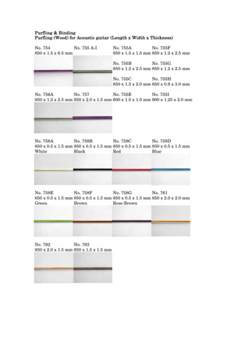
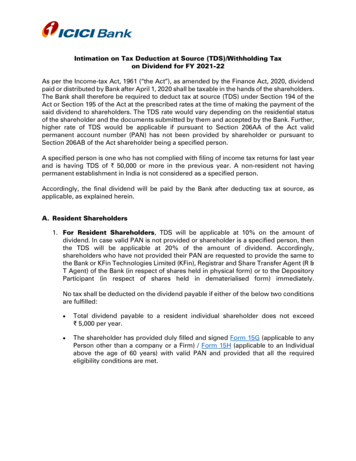
Tiny Serial-to-Ethernet Device Server1. IntroductionThe tDS-700 is a series of Serial-to-Ethernet device servers that aredesigned to add Ethernet and Internet connectivity to any RS-232and RS-422/485 device, and to eliminate the cable length limitationof legacy serial communications. By using the VxCommDriver/Utility, the built-in COM Port of the tDS-700 series can bevirtualized to a standard PC COM Port in Windows. Therefore,users can transparently access or monitor serial devices over theInternet/Ethernet without the need for software modification.tDS-700 device servers can be used to create a pair-connection application (as well as serial-bridgeor serial-tunnel), and then route data between two serial devices via TCP/IP. This is useful whenconnecting mainframe computers, servers or other serial devices that do not themselves haveEthernet capability. By virtue of its protocol independence and flexibility, the tDS-700 meets thedemands of virtually any network-enabled application.Copyright 2018 ICP DAS CO., Ltd. All Rights Reserved.-6 -
Tiny Serial-to-Ethernet Device ServerIn harsh industrial environments, the tDS-700 series (for i version) also adds 3000 VDC and /- 4 kVESD protection component that diverts the potentially damaging charge away from sensitive circuitto protects the module and equipment from the sudden and momentary electric current.To achieve maximum space savings, the tDS-700 is offered in an amazingly small form-factor thatenables it to be easily installed anywhere, even directly attached to a serial device or embeddedinto a machine. The tDS-700 features a powerful 32-bit MCU that allows it to efficiently handlenetwork traffic. The tDS-700 offers true IEEE 802.3af-compliant (classification, Class 1) Power-overEthernet (PoE) functionality using a standard category 5 Ethernet cable that allows it to receivepower from a PoE switch such as the NS-205PSE. If there is no PoE switch available on site, the tDS700 can accepts power input from a DC adapter.Comparison of Device Servers:SeriesPPDSPDSDStDStGWVirtual COM -Programmable ---PoE -- Modbus Gateway --- 1 Sockets/Port10 ve,Entry-levelFeaturesMulti-clientRemarksAbout 20 SocketsProfessionalPowerfulIsolation forDS-715Copyright 2018 ICP DAS CO., Ltd. All Rights Reserved.-7 -
Tiny Serial-to-Ethernet Device Server1.1 Ethernet SolutionsNowadays, the Ethernet protocol has become the foremost standard for local area networks.Connectivity via the Internet snow common in many of the latest applications from homeappliances, to vending machines, to testing equipment, to UPS, etc. An Ethernet network can linkoffice automation and industrial control networks, access remote systems and share data andinformation between machines from multiple vendors, and also provides a cost-effective solutionfor industrial control networks.Copyright 2018 ICP DAS CO., Ltd. All Rights Reserved.-8 -
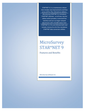
Tiny Serial-to-Ethernet Device Server1.2 VxComm TechnologyIn general, writing a TCP/IP program is more difficult than writing a COM Port program. Anotherissue is that perhaps the existing the COM Port communication system was built many years agoand is now outdated.As a result, a new technology, VxComm was developed to virtualize the COM Ports of the tDS-700to allow up to 256 COM Ports to be used on a central computer. The VxComm driver saves timewhen accessing serial devices through the Ethernet without the need for reprogramming the COMPort software on the PC.Copyright 2018 ICP DAS CO., Ltd. All Rights Reserved.-9 -
Tiny Serial-to-Ethernet Device ServerThe VxComm driver controls all the details of the Ethernet TCP/IP programming technique,meaning that, with the assistance of tDS-700 and VxComm technology, your COM Port program willbe able to access your serial devices through the Ethernet in the same way as through a COM Port.Copyright 2018 ICP DAS CO., Ltd. All Rights Reserved.-10 -
Tiny Serial-to-Ethernet Device Server1.3 Web Server TechnologyWeb server technology enables the tDS-700 to be configured via a standard web browser interface,e.g. Google Chrome, Internet Explorer, or Firefox, etc. This means that it is easy to check theconfiguration of thetDS-700 via an Ethernet network without needing to install any other softwaretools, thereby reducing the learning curve required for maintaining the device.Copyright 2018 ICP DAS CO., Ltd. All Rights Reserved.-11 -
Tiny Serial-to-Ethernet Device Server2. Hardware InformationThis chapter provides a detailed description of the front panel, the hardware specifications, the pinassignments, the wiring notes and the dimensions for the tDS-700 series modules.2.1 itDS-735tDS-735iSystemCPU32-bit ARMCommunication Interface10/100 Base-TX, 8-pin RJ-45 x 1, (Auto-negotiating, Auto-MDI/MDIX, LED indicator)EthernetPoE (IEEE 802.3af, Class eRS-232tDS-718(i):3-wire RS-232COM15-wire 3--3-wireRS-2323-wireRS-232Self-TunerBias ResistorRS485NodeUARTPower IsolationSignal IsolationESD ProtectionCOM Port FormatBaud RateData BitParityStop BitPowerYes, automatic RS-485 direction controlYes, 1 KΩ254 (max.)16c550 or compatible1000 VDC for tDS-722i / 732i / 718i-D only3000 VDC for tDS-712i / 715i / 725i / 735i / 718i / 724i / 734i only /-4 kVPower InputPower ConsumptionMechanismConnectortDS-718i-D:5-wire RS-2322-wire RS-4854-wire RS-422115200 bps Max.5, 6, 7, 8None, Odd, Even, Mark, Space1, 2PoE: IEEE 802.3af, Class 1DC jack: 12 48 VDC0.07 A @ 24 VDCMale DB-9 x1 for tDS-712(i)/718i-D and tDSM-71210-Pin Removable Terminal Block x 1 for i)/734(i)DIN-RailPlasticMetal PlasticMountingCaseEnvironmentOperating Temperature-25 75 CStorage Temperature -30 80 CHumidity10 90% RH, non-condensingNote: COM1/COM2/COM3 TCP Port 10001/10002/10003Copyright 2018 ICP DAS CO., Ltd. All Rights Reserved.-12 -
Tiny Serial-to-Ethernet Device Server2.2 Features Incorporates any RS-232/422/485 serial device in Ethernet Data transmission via Virtual COM or raw TCP connection VxComm Driver for 32-bit and 64-bit Windows XP/7/8/2012/2016/10 Max. connections: 1 socket per serial port is suggested Supports pair-connection (serial-bridge, serial-tunnel) applications Supports TCP client-mode and TCP server-mode operations Supports UDP responder for device discovery (UDP Search) Static IP or DHCP network configuration Easy firmware update via the Ethernet (BOOTP, TFTP) Tiny Web server for configuration (HTTP) Contains a 32-bit MCU that efficiently handles network traffic 10/100 Base-TX Ethernet, RJ-45 x1 (Auto-negotiating, auto MDI/MDIX, LED Indicators) Includes redundant power inputs: PoE (IEEE 802.3af, Class 1) and DC jack Allows automatic RS-485 direction control Power or Signal isolation for i versions /- 4 kV ESD protection Male DB-9 or terminal block connector for easy wiring Tiny form-factor and low power consumption RoHS compliant with no Halogen Cost-effective device serversCopyright 2018 ICP DAS CO., Ltd. All Rights Reserved.-13 -
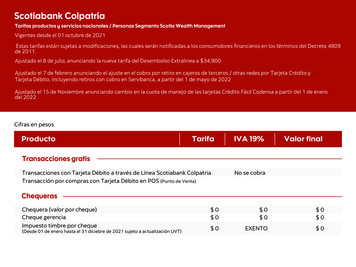
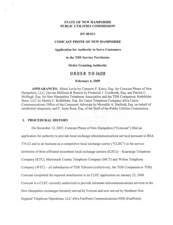
Tiny Serial-to-Ethernet Device Server2.3 Appearance5. Serial COM Ports4. LED indicator6. DIN-Rail Mounting3. Operating ModeSwitch1. PoE and EthernetRJ-45 Jack2. 12 to 48 VDC JackPoE and Ethernet RJ-45 JackThe tDS-700 series module is equipped with an RJ-45 jack that is used as the 10/100 Base-TXEthernet port and features networking capabilities. When an Ethernet link is detected and anEthernet packet is received, the Link/Act LED (Orange) indicator will be illuminated. When power issupplied via PoE (Power-over-Ethernet), the PoE LED (Green) indicator will be illuminated. 12 to 48 VDC JackThe tDS-700 series is equipped with a 12VDC to 48 VDC jack that can be used to connect a powersupply. If no PoE switch is available on site, a DC adapter can be used to power the tDS-700 seriesmodule.Copyright 2018 ICP DAS CO., Ltd. All Rights Reserved.-14 -
Tiny Serial-to-Ethernet Device ServerOperating Mode SwitchRun Mode: Firmware operationInit Mode: Configuration modeFor tDS-700 series modules, the operating mode switch is set to the Run position by default. Inorder to update the firmware for the tDS-700 series module, the switch must be moved from theRun position to the Init position. The switch must be returned to the Run position after the updateis complete.LED IndicatorOnce power is supplied to the tDS-700 series module, the system LED (S1) indicator will illuminate.An overview of the S1 LED functions is given below:FunctionColorS1 LED BehaviorSteady ONRunning FirmwareNetwork ReadySlow flashing – Once every 3 secondsRedSerial Port BusyRapid flashing – Once every 0.2 secondsThe following serial port LED indicators are tDS-718i-D only. You can change the serial interface viaweb server. An overview of the serial Port LED functions is given below:FunctionRS-232RS-485RS-422LED BehaviorCopyright 2018 ICP DAS CO., Ltd. All Rights Reserved.-15 -
Tiny Serial-to-Ethernet Device ServerSerial COM PortsThe number of serial COM Ports available depends on the type of tDS-700 series module. For moredetailed information regarding the pin assignments for the Serial COM ports, refer to Section 2.5“Pin Assignments”.DIN-Rail MountingThe tDS-700 series modules include simple rail clips on thebottom of the chassis that allow them to be reliablymounted on a DIN-Rail or a wall. For more detailedinformation regarding DIN-Rail Mounting, refer to theillustration in figure below.Mounting on a DIN-Rail Dismounting form a DIN-Rail Copyright 2018 ICP DAS CO., Ltd. All Rights Reserved.-16 -
Tiny Serial-to-Ethernet Device Server2.4 DimensionsThe following diagrams provide the dimensions of the tDS-700 series module and CA-002 cable thatcan be used as a reference when defining the specifications and the DC power supply plug for anycustom enclosures. All dimensions are in millimeters.2.4.1 tDS-700 Series Module tDS-712: tDSM-712:Copyright 2018 ICP DAS CO., Ltd. All Rights Reserved.-17 -
Tiny Serial-to-Ethernet Device Server tDS-712i/718i-D: i)/734(i):Copyright 2018 ICP DAS CO., Ltd. All Rights Reserved.-18 -
Tiny Serial-to-Ethernet Device Server2.4.2CA-002 CableP2P112REDBLACKOPENOPENCopyright 2018 ICP DAS CO., Ltd. All Rights Reserved.-19 -
Tiny Serial-to-Ethernet Device Server2.5 Pin 12Terminal No.COM1tDS-712iPin 2tDS-722itDS-722/tDS-722iTerminal No.COM2COM1Pin D101TxD1TxD1Copyright 2018 ICP DAS CO., Ltd. All Rights Reserved.-20 -
Tiny Serial-to-Ethernet Device ServertDS-732/tDS-732itDS-732Terminal No.COM3COM2COM1tDS-732iPin minal No.RS-485/RS-422Pin /A05GNDISO.GND04RxD1-RxD1-03RxD1 RxD1 02TxD1-/D1-TxD1-/D1-01TxD1 /D1 TxD1 /D1 Copyright 2018 ICP DAS CO., Ltd. All Rights Reserved.-21 -
Tiny Serial-to-Ethernet Device ServertDS-725/tDS-725itDS-725Terminal No.COM2COM1tDS-725iPin SO.GND05D2-D2-04D2 D2 03GNDISO.GND02D1-D1-01D1 D1 tDS-735tDS-735itDS-735/tDS-735iTerminal No.COM3COM2COM1Pin Assignment10F.G.F.G.09GNDISO.GND08D3-D3-07D3 D3 06GNDISO.GND05D2-D2-04D2 D2 03GNDISO.GND02D1-D1-01D1 D1 Copyright 2018 ICP DAS CO., Ltd. All Rights Reserved.-22 -
Tiny Serial-to-Ethernet Device ServertDS-718/tDS-718itDS-718Terminal No.RS-232RS-485/RS-422tDS-718iPin 06TxD1TxD105GNDISO.GND04RxD1-RxD1-03RxD1 RxD1 02TxD1-/D1-TxD1-/D1-01TxD1/D1 TxD1/D1 RS-232RS-422tDS-718i-DTerminal No.COM1RS-485Pin D--03TxDRxD -02RxDTxD Data 01-TxD-Data-Copyright 2018 ICP DAS CO., Ltd. All Rights Reserved.-23 -
Tiny Serial-to-Ethernet Device ServertDS-724/tDS-724itDS-724Terminal No.COM2COM1tDS-724iPin -D1-01D1 D1 tDS-734tDS-734itDS-734/tDS-734iTerminal No.COM3COM2COM1Pin -D1-01D1 D1 Copyright 2018 ICP DAS CO., Ltd. All Rights Reserved.-24 -
Tiny Serial-to-Ethernet Device Server2.6 Wiring Notes for RS-232/485/422 InterfacesRS-232 Wiring3-wire RS-232 Connection5-wire RS-232 ConnectionNote: FGND is the frame ground that is soldered to the metal shield on the DB-9 cable.Copyright 2018 ICP DAS CO., Ltd. All Rights Reserved.-25 -
Tiny Serial-to-Ethernet Device ServerRS-422 WiringRS-485 WiringNotes:1. Usually, you have to connect all signal grounds of RS-422/485 devices together to reduce common-modevoltage between devices.2. Twisted-pair cable must be used for the DATA /- wires.3. Both two ends of the cable may require a termination resistor connected across the two wires (DATA andDATA-). Typically 120 Ω resisters are used.4. The Data and B pins are positive-voltage pins, and Data- and A pins are negative-voltage pins in theabove figure. The B/A pins may be defined in another way depending on devices, please check it first.Copyright 2018 ICP DAS CO., Ltd. Al
tDS-700 device servers can be used to create a pairconnection application (as well as serial- bridge - or serialtunnel), and then route data between two serial devices via TCP/IP.