Transcription
1997 Mazda MX-5 Miata1997 AUTOMATIC TRANSMISSIONS NC4A-EL Electronic Controls1997 AUTOMATIC TRANSMISSIONSNC4A-EL Electronic ControlsAPPLICATIONTRANSMISSION APPLICATIONVehicleMiataTransmission ModelNC4A-ELCAUTION: Vehicle is equipped with Supplemental Restraint System (SRS). Whenservicing vehicle, use care to avoid accidental air bag deployment. SRSrelated components are located in steering column, center console andinstrument panel. DO NOT use electrical test equipment on these circuits.If necessary, deactivate SRS before servicing components. See AIR BAGDEACTIVATION PROCEDURES article in GENERAL INFORMATION.CAUTION: Disconnecting battery on models equipped with anti-theft radio requirecanceling of anti-theft operation. See appropriate AUTOMATICTRANSMISSION SERVICING article in TRANSMISSION SERVICING. Referto vehicle owner's manual to identify radio type.DESCRIPTIONThe NC4A-EL series is a 4-speed electronically controlled automatic transmission. Five solenoids attached tovalve body control shift changes. Solenoids are controlled by the Transmission Control Module (TCM).NOTE:Torque Converter Clutch (TCC) solenoid is also known as lock-up solenoid,TCC lock-up or 4th gear solenoid.The TCM receives information from various input devices. The TCM uses this information to control followingsolenoids: Shift solenoids for transmission shifting.Torque Converter Clutch (TCC) solenoid for torque converter clutch lock-up.3-2 control solenoid for downshift timing control.A HOLD switch is mounted on the shift lever. HOLD function may be activated in "D", "S" or "L" gears bypressing HOLD button. In "L" and "S" positions, vehicle is held in selected gear and no upshift or downshifttakes place. This function is used for driving up steep inclines or for engine braking assistance when descendingsteep grades. If activated in "D" position a 1-2 and 2-3 upshift is permitted when starting from a stop, but afterthe 2-3 upshift the vehicle is locked in "D" until it comes to a complete stop. The 1-2 and 2-3 upshift pattern ischanged to a "short shift" specification. This function is used for starting off or driving on slippery surfaces.Pushing HOLD button again deactivates system.MicrosoftSunday, July 05, 2009 1:35:381:35:03 PMPage 1 2005 Mitchell Repair Information Company, LLC.
1997 Mazda MX-5 Miata1997 AUTOMATIC TRANSMISSIONS NC4A-EL Electronic ControlsOPERATIONTCMTCM receives information from various input devices and uses this information to control solenoids ontransmission valve body for transmission shifting and torque converter clutch engagement.TCM automatically switches from NORMAL mode to POWER mode corresponding to driving condition in"D" range. Upshifts and downshifts are performed at a higher speed in POWER mode than in NORMAL mode.TCM contains a self-diagnostic system, which will store Diagnostic Trouble Codes (DTC) if a failure orproblem exists in electronic control system. DTC can be retrieved to determine problem area. See SELFDIAGNOSTIC SYSTEM . TCM is located under left side of instrument panel, above fuse block.TCM INPUT DEVICES & SIGNALS4th Gear Inhibit SignalSignal is input to TCM when cruise control is on. Signal detects when difference between target speed andactual speed exceeds specification.HOLD SwitchHOLD switch delivers input to TCM to indicate gears preferred by operator. Switch is located on shift leverhandle. HOLD switch is canceled when ignition switch is turned off.Input/Turbine Speed SensorSensor is a magnetic pick-up type pulse generator that monitors input shaft speed. AC waveform is input toTCM by output speed sensor. Sensor is located on front of transmission, back of converter housing.Throttle Position (TP) SensorTP sensor delivers an input signal to TCM indicating throttle valve position (opening). TP sensor is located onside of throttle body.Transmission Range SwitchTransmission range switch delivers an input signal to TCM indicating shift lever position. Switch is located onside of transmission.Transmission Fluid Temperature (TFT) SensorTFT sensor is threaded into cooler line banjo mounting on side of transmission case. Sensor sends signal toTCM indicating fluid temperature.Vehicle Speed SensorMicrosoftSunday, July 05, 2009 1:35:03 PMPage 2 2005 Mitchell Repair Information Company, LLC.
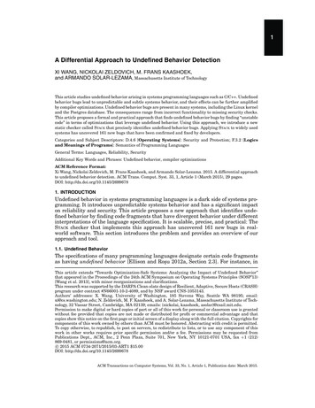
1997 Mazda MX-5 Miata1997 AUTOMATIC TRANSMISSIONS NC4A-EL Electronic ControlsSensor is a cable driven pulse generator that is part of speedometer. Pulse signals are sent to TCM.TCM OUTPUT DEVICESHOLD Indicator LightReceives signal from TCM to indicate switch position.Inhibitor SignalWhen shift selector lever is moved from Park or Neutral to another gear, signal is sent from TCM to ECM toregulate fuel injection volume for shift shock prevention.Shift Solenoids & 3-2 Control SolenoidThe TCM controls transmission shifting by delivering an output signal to operate proper solenoid. 3-2 controlsolenoid affects downshift timing. See SOLENOID OPERATION table. Hydraulic pressure is retained whensolenoid is off and drained when solenoid is on. Solenoids are located on transmission valve body. See Fig. 1 .SOLENOID OPERATIONShift Lever Position"D" (Drive)1st Gear2nd Gear3rd Gear4th Gear"2" (Second)1st Gear2nd Gear"L" (Low)1st Gear"R" (Reverse)"N" or "P"1-2 Shift Solenoid 2-3 Shift Solenoid3-4 OnOnOnOnOffOnOnOffOnOnOnOnTCC Solenoid ValveSolenoid valve is ON/OFF type controlled by TCM. Solenoid regulates pilot pressure to applied to lock-upcontrol plug. Hydraulic pressure is retained when solenoid is on and drained when solenoid is off. Solenoid islocated on side of case. See Fig. 1 .MicrosoftSunday, July 05, 2009 1:35:03 PMPage 3 2005 Mitchell Repair Information Company, LLC.
1997 Mazda MX-5 Miata1997 AUTOMATIC TRANSMISSIONS NC4A-EL Electronic ControlsFig. 1: Locating Solenoid ValvesCourtesy of MAZDA MOTORS CORP.SELF-DIAGNOSTIC SYSTEMSYSTEM DIAGNOSISNOTE:Before testing transmission, ensure fluid level is correct. Ensure engine startswith shift lever in Park and Neutral to ensure proper adjustment of transmissionrange switch. Transmission Control Module (TCM) must first be checked forstored codes. See RETRIEVING TROUBLE CODES .TCM monitors transmission operation and contains a self-diagnostic system which stores a Diagnostic TroubleCode (DTC) if an electronic control system failure or component malfunction exists. If a problem exists in anyof the solenoids or speed sensors and DTC is set, TCM will deliver a signal to blink the HOLD indicator lighton instrument panel to warn the driver. DTC may be set if a failure exists and can be retrieved for transmissiondiagnosis.RETRIEVING TROUBLE CODESNOTE:Before retrieving DTC, ensure proper battery voltage exists for self-diagnosticsystem operation. If any DTC are present other than those listed below, seeMicrosoftSunday, July 05, 2009 1:35:03 PMPage 4 2005 Mitchell Repair Information Company, LLC.
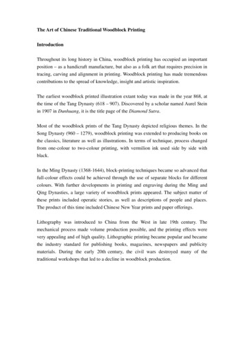
1997 Mazda MX-5 Miata1997 AUTOMATIC TRANSMISSIONS NC4A-EL Electronic Controlsappropriate SELF-DIAGNOSTIC SYSTEM article in ENGINE PERFORMANCE.Using Scan ToolEnsure ignition is in OFF position. Connect scan tool to Data Link Connector (DLC) located under left side ofinstrument panel, near center console. Turn ignition switch to ON position. Check for stored DTC. SeeDIAGNOSTIC TROUBLE CODE IDENTIFICATION table. For trouble shooting of codes, seeDIAGNOSTIC TESTS .MicrosoftSunday, July 05, 2009 1:35:03 PMPage 5 2005 Mitchell Repair Information Company, LLC.
1997 Mazda MX-5 Miata1997 AUTOMATIC TRANSMISSIONS NC4A-EL Electronic ControlsFig. 2: Locating Data Link Connector (DLC) LocationCourtesy of MAZDA MOTORS CORP.DIAGNOSTIC TROUBLE CODE IDENTIFICATION(1)DTC No.P0705Probable CauseTransmission Range Sensor MalfunctionMicrosoftSunday, July 05, 2009 1:35:03 PMPage 6 2005 Mitchell Repair Information Company, LLC.
1997 Mazda MX-5 Miata1997 AUTOMATIC TRANSMISSIONS NC4A-EL Electronic ControlsP0706P0710Transmission Range Sensor Range/Performance(2)TFT Sensor Malfunction(2)P0711TFT Sensor Range/PerformanceP0715Input/Turbine Speed SensorP0725Engine Speed Input Circuit MalfunctionP0731Incorrect 1st Gear RatioP0732Incorrect 2nd Gear RatioP0733Incorrect 3rd Gear RatioP0734Incorrect 4th Gear RatioP0740TCC System MalfunctionP07501-2 Shift SolenoidP07552-3 Shift SolenoidP07603-4 Shift SolenoidP1720Vehicle Speed SensorP1743Lock-Up Solenoid ValveP17653-2 Timing Control Solenoid ValveP1790Throttle Position SensorP1795Idle Switch(1) Check listed component for probable cause. Check wiring and connection of specified component.(2)Transmission Fluid Temperature.CLEARING CODESTo clear DTC stored in TCM, use scan tool. See scan tool instruction manual. Road test vehicle.COMPONENT LOCATIONCOMPONENT LOCATIONDescriptionEngine Control ModuleInput/Turbine Speed SensorShift SolenoidsTCC Lock-Up SolenoidTransmission Control Unit3-2 Control ValveTFT SensorVehicle Speed SensorLocationBehind Passenger SeatMounted To 4th Gear CaseSee Fig. 1See Fig. 1Above Fuse BoxSee Fig. 1Mounted In-Line To Cooler LineMounted In SpeedometerCOMPONENT CONNECTOR IDENTIFICATIONMicrosoftSunday, July 05, 2009 1:35:03 PMPage 7 2005 Mitchell Repair Information Company, LLC.
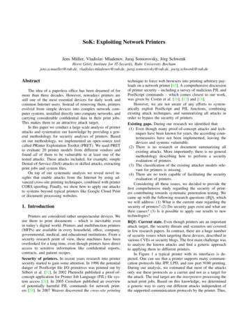
1997 Mazda MX-5 Miata1997 AUTOMATIC TRANSMISSIONS NC4A-EL Electronic ControlsCOMPONENT CONNECTOR IDENTIFICATION (1)ComponentEngine Control Module (ECM)Hold SwitchSee Fig.Fig. 5(2)(3)Instrument ClusterTransmission Control Module (TCM)Valve Body SolenoidsFig. 4(4)(1)For connector location see Fig. 3 .(2)See HOLD SWITCH under COMPONENT TESTING.(3)See VEHICLE SPEED SENSOR (VSS) under COMPONENT TESTING.(4)See SOLENOID VALVES under COMPONENT TESTING.Fig. 3: Locating Transmission Component ConnectorsMicrosoftSunday, July 05, 2009 1:35:03 PMPage 8 2005 Mitchell Repair Information Company, LLC.
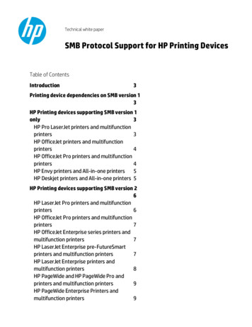
1997 Mazda MX-5 Miata1997 AUTOMATIC TRANSMISSIONS NC4A-EL Electronic ControlsCourtesy of MAZDA MOTORS CORP.Fig. 4: Identifying TCM Component Connector TerminalsCourtesy of MAZDA MOTORS CORP.Fig. 5: Identifying ECM Component Connector TerminalsCourtesy of MAZDA MOTORS CORP.DIAGNOSTIC TESTSNOTE:For connector terminal identification, see COMPONENT CONNECTORIDENTIFICATION table under SELF-DIAGNOSTIC SYSTEM. For circuit or wirecolor identification, see appropriate wiring diagram in WIRING DIAGRAMS .DTC P0705: TRANSMISSION RANGE SWITCH CIRCUIT MALFUNCTION & DTC P0706:TRANSMISSION RANGE SWITCH CIRCUIT RANGE/PERFORMANCEConditionNo signal is received from range switch or more than 2 signals are received at one time. Possible causes foreither condition are: Transmission range switch malfunction.Damaged wiring or connectors between transmission range switch and TCM.TCM malfunction.Diagnosis & Repair ProcedureMicrosoftSunday, July 05, 2009 1:35:03 PMPage 9 2005 Mitchell Repair Information Company, LLC.
1997 Mazda MX-5 Miata1997 AUTOMATIC TRANSMISSIONS NC4A-EL Electronic Controls1. Ensure all connections are clean and tight. Repair as needed. Turn ignition on. Using voltmeter,backprobe TCM connector (as applicable). Measure voltage between ground and specified terminal. SeeDTC P0705 VOLTAGE TEST table. If all voltages are within specification, go to step 5 . If any voltageis not within specification, go to next step.DTC P0705 VOLTAGE TESTTCM -142F02H10-142H0Range Switch Position"P" Or "N""R", "D", "S" Or "L""D"All Except "D""S"All Except "S""L"All Except "L"2. Check continuity of circuits between transmission range switch and TCM. See appropriate wiringdiagram in WIRING DIAGRAMS . Repair as needed. If all circuits are okay, go to next step.3. Disconnect negative battery cable. Disconnect transmission range switch harness connector. Inspectcontinuity of transmission range switch internal circuits. See TRANSMISSION RANGE SWITCHunder COMPONENT TESTING. Replace as needed. If switch is okay, go to next step.4. Reconnect negative battery cable. Turn ignition on. Measure voltage at terminal "I" (Black/Blue wire) ontransmission range switch harness connector. If battery voltage does not exist, repair Black/Blue wirebetween switch and ignition switch. If battery voltage exists, go to next step.5. Road test vehicle. Retrieve DTC. If code P0705 is still present, replace TCM. If code is no longer present,system is okay.DTC P0710: TRANSMISSION FLUID TEMPERATURE (TFT) SENSOR CIRCUIT MALFUNCTION& DTC P0711: TRANSMISSION FLUID TEMPERATURE (TFT) SENSOR CIRCUITRANGE/PERFORMANCEConditionVoltage input to TCM is less than .1 volt or greater than 5.0 volts. Possible causes for condition are: Transmission fluid temperature sensor malfunction.Damaged wiring or connectors between transmission fluid temperature sensor and TCM.TCM malfunction.Diagnosis & Repair Procedure1. Ensure all connections are clean and tight. Repair as needed. Turn ignition on. Access TCM connectors.Using voltmeter, backprobe harness connectors. DO NOT disconnect connectors. Go to next step.MicrosoftSunday, July 05, 2009 1:35:03 PMPage 10 2005 Mitchell Repair Information Company, LLC.
1997 Mazda MX-5 Miata1997 AUTOMATIC TRANSMISSIONS NC4A-EL Electronic Controls2. Measure voltage between terminal No. 1G (Green wire) and No. 2P (Black/Light Blue wire) on TCMconnector. Voltage should be about 3.3 volts at 77 F (25 C). If voltage is within specifications, go to step6 . If voltage is not within specifications, go to next step.3. Turn ignition off. Disconnect TCM harness connector. Measure resistance between terminals No. 1G andNo. 2P. See TFT SENSOR SPECIFICATIONS table. If resistance is within specification, go to step 6 .If resistance is not within specification, go to next step.4. Inspect TFT sensor. Disconnect TFT sensor harness connector. Measure resistance between connectorterminals. See TFT SENSOR SPECIFICATIONS table. If resistance is within specification, go to step6 . If resistance is not within specification, replace TFT sensor.5. Check continuity of circuits between TFT sensor and TCM. See appropriate wiring diagram in WIRINGDIAGRAMS . Repair as needed. If circuit is okay, go to next step.6. Reconnect all harness connectors. Road test vehicle. Retrieve DTC. If code P0710 or P0711 is stillpresent, replace TCM. If code is no longer present, system is okay.TFT SENSOR SPECIFICATIONSFluid Temperature68 F (20 C)140 F (60 C)176 F (80 C)k/ohms2.5.6.35DTC P0715: INPUT/TURBINE SPEED SENSORConditionInput/Turbine speed sensor signal is not input to TCM when vehicle is moving. Possible causes for conditionare: Input/Turbine speed sensor malfunction.Damaged wiring or connectors between turbine speed sensor and TCM.TCM malfunction.Diagnosis & Repair Procedure1. Turn ignition on. Using voltmeter, backprobe TCM harness connector. DO NOT disconnect connector.Measure AC voltage between terminals No. 2J (positive) and No. 2L (negative). Voltage should be 0-.1volts when idling and zero with engine stopped. If voltage is within specification, go to step 5 . If voltageis not within specification, go to next step.2. Turn ignition off. Disconnect TCM harness connector. Check for continuity between terminals No. 2J(Yellow/Green wire) and No. 2L (Yellow/Blue wire). If continuity is present, go to step 5 . If continuityis not present, go to next step.3. Inspect sensor. See INPUT/TURBINE SPEED SENSOR under COMPONENT TESTING. Repair asneeded. If sensor is okay, go to next step.4. Check continuity of circuits between input/turbine speed sensor and TCM. See appropriate wiringdiagram in WIRING DIAGRAMS . Repair as needed. If circuits are okay, go to next step.MicrosoftSunday, July 05, 2009 1:35:04 PMPage 11 2005 Mitchell Repair Information Company, LLC.
1997 Mazda MX-5 Miata1997 AUTOMATIC TRANSMISSIONS NC4A-EL Electronic Controls5. Reconnect all harness connectors. Road test vehicle. Retrieve DTC. If code P0715 is still present, replacePCM. If code is no longer present, system is okay.DTC P0725: ENGINE SPEED INPUT CIRCUIT MALFUNCTIONNOTE:If DTC P0335 is also present, repair it first and then proceed with this test. Go toappropriate SELF-DIAGNOSTICS article in ENGINE PERFORMANCE andperform test.ConditionEngine speed input signal is not input to TCM. Possible causes are: Crankshaft position sensor malfunction.Damaged wiring or connectors between ECM and TCM.ECM malfunction.TCM malfunction.Diagnosis & Repair Procedure1. Ensure all connections are clean and tight. Repair as needed. Turn ignition on. Using voltmeter,backprobe TCM harness connector. DO NOT disconnect connector.2. Measure voltage between ground and terminal No. 1N (White wire) on TCM harness connector. Voltageshould be zero or 4.5-5.5 volts with engine stopped or 2-3 volts with engine idling. If voltage is withinspecifications, go to step 7 . If voltage is not within specifications, go to next step.3. Ignition off. Measure continuity between terminal No. 1N (White wire) on TCM harness connector andterminal No. 4F (White wire) on ECM harness connector. If continuity is not present, repair wiring thengo to step 7 .4. Using voltmeter, backprobe ECM harness connector. Measure voltage between ground and terminal No.4H (Yellow/White wire). Voltage should be less than one volt with engine stopped or greater than onevolt with engine idling. If voltage is within specifications, go to step 7 . If voltage is not withinspecifications, go to next step.5. Inspect crankshaft position sensor. See appropriate SYSTEM & COMPONENT TESTS article inENGINE PERFORMANCE. Replace as needed. If sensor is okay, go to next step.6. Turn ignition off. Using ohmmeter, backprobe TCM harness connector. DO NOT disconnect connector.Measure resistance between terminals 1N (White wire) and 2P (Black/Light Green wire). If resistance is7.2-8.0 ohms, go to next step. If resistance is not 7.2-8.0 ohms, replace TCM.7. Reconnect all harness connectors. Road test vehicle. Retrieve DTC. If code P0725 is still present, replaceTCM. If code is no longer present, problem is intermittent.DTC P0731: INCORRECT 1ST GEAR RATIONOTE:If any following DTC is also present, repair it first and then proceed with thistest: DTC P0750 , P0755 , P0760 .MicrosoftSunday, July 05, 2009 1:35:04 PMPage 12 2005 Mitchell Repair Information Company, LLC.
1997 Mazda MX-5 Miata1997 AUTOMATIC TRANSMISSIONS NC4A-EL Electronic ControlsConditionTCM outputs solenoid pattern of 1st gear when gear ratio is other than 1st gear. Possible causes are: Low ATF level.Low line pressure.Control valve stuck.Solenoid valve malfunction.TCM malfunction.Diagnosis & Repair Procedure1. Ensure ATF level and condition is okay. Check line pressure and stall speed. See LINE PRESSURETEST and STALL SPEED under TESTING in MAZDA NC4A-EL OVERHAUL article. Repair anycomponents as necessary. If malfunction is not present, go to next step.2. Inspect 1-2, 2-3 and 3-4 shift solenoid valves. See SOLENOID VALVES under COMPONENTTESTING. Repair as needed. If solenoid valves are okay, go to next step.3. Inspect valve body. Ensure all valves operate smoothly. Repair as needed. If valve body is okay, go tonext step.4. Clear DTC and retest. See CLEARING CODES . If code P0731 is still present, replace TCM. If code isno longer present and symptom still exists, problem may be caused by intermittent clutch slippage.Further investigation may be required. See MAZDA NC4A-EL OVERHAUL article.DTC P0732: INCORRECT 2ND GEAR RATIONOTE:If any following DTC is also present, repair it first and then proceed with thistest: DTC P0750 , P0755 , P0760 .ConditionTCM outputs solenoid pattern of 2nd gear when gear ratio is other than 2nd gear. Possible causes are: Low ATF level.Direct clutch slippage.One-way clutch slippage.Faulty band servo.Low line pressure.Control valve stuck.Solenoid valve malfunction.TCM malfunction.Diagnosis & Repair ProcedureMicrosoftSunday, July 05, 2009 1:35:04 PMPage 13 2005 Mitchell Repair Information Company, LLC.
1997 Mazda MX-5 Miata1997 AUTOMATIC TRANSMISSIONS NC4A-EL Electronic Controls1. Ensure ATF level and condition is okay. Check line pressure and stall speed. See LINE PRESSURETEST and STALL SPEED under TESTING in MAZDA NC4A-EL OVERHAUL article. Repair anycomponents as necessary. If malfunction is not present, go to next step.2. Inspect 1-2, 2-3 and 3-4 shift solenoid valves. See SOLENOID VALVES under COMPONENTTESTING. Repair as needed. If solenoid valves are okay, go to next step.3. Inspect valve body. Ensure all valves operate smoothly. Repair as needed. If valve body is okay, go tonext step.4. Clear DTC and retest. See CLEARING CODES . If code P0732 is still present, replace PCM. If code isno longer present and symptom still exists, problem may be caused by intermittent clutch slippage.Further investigation may be required. See MAZDA NC4A-EL OVERHAUL article.DTC P0733: INCORRECT 3RD GEAR RATIONOTE:If any following DTC is also present, repair it first and then proceed with thistest: DTC P0750 , P0755 , P0760 .ConditionTCM outputs solenoid pattern of 3rd gear when gear ratio is other than 3rd gear. Possible causes are: Low ATF level.Direct clutch slippage.One-way clutch slippage.Front clutch slippage.Low line pressure.Control valve stuck.Solenoid valve malfunction.TCM malfunction.Diagnosis & Repair Procedure1. Ensure ATF level and condition is okay. Check line pressure and stall speed. See LINE PRESSURETEST and STALL SPEED under TESTING in MAZDA NC4A-EL OVERHAUL article. Repair anycomponents as necessary. If malfunction is not present, go to next step.2. Inspect 1-2, 2-3 and 3-4 shift solenoid valves. See SOLENOID VALVES under COMPONENTTESTING. Repair as needed. If solenoid valves are okay, go to next step.3. Inspect valve body. Ensure all valves operate smoothly. Repair as needed. If valve body is okay, go tonext step.4. Clear DTC and retest. See CLEARING CODES . If DTC P0733 is still present, replace PCM. If code isno longer present and symptom still exists, problem may be caused by intermittent clutch slippage.Further investigation may be required. See MAZDA NC4A-EL OVERHAUL article.DTC P0734: INCORRECT 4TH GEAR RATIOMicrosoftSunday, July 05, 2009 1:35:04 PMPage 14 2005 Mitchell Repair Information Company, LLC.
1997 Mazda MX-5 Miata1997 AUTOMATIC TRANSMISSIONS NC4A-EL Electronic ControlsNOTE:If any following DTC is also present, repair it first and then proceed with thistest: DTC P0750 , P0755 , P0760 .ConditionTCM outputs solenoid pattern of 3rd gear when gear ratio is other than 3rd gear. Possible causes are: Low ATF level.Band servo slippage.Front clutch slippage.Low line pressure.Control valve stuck.Solenoid valve malfunction.TCM malfunction.Diagnosis & Repair Procedure1. Ensure ATF level and condition is okay. Check line pressure and stall speed. See LINE PRESSURETEST and STALL SPEED under TESTING in MAZDA NC4A-EL OVERHAUL article. Repair anycomponents as necessary. If malfunction is not present, go to next step.2. Inspect 1-2, 2-3 and 3-4 shift solenoid valves. See SOLENOID VALVES under COMPONENTTESTING. Repair as needed. If solenoid valves are okay, go to next step.3. Inspect valve body. Ensure all valves operate smoothly. Repair as needed. If valve body is okay, go tonext step.4. Clear DTC and retest. See CLEARING CODES . If DTC P0734 is still present, replace PCM. If code isno longer present and symptom still exists, problem may be caused by intermittent clutch slippage.Further investigation may be required. See MAZDA NC4A-EL OVERHAUL article.DTC P0740: TORQUE CONVERTER CLUTCH MALFUNCTIONConditionTCM outputs TCC signal, but TCC does not operate. Possible causes are: Low ATF level.Low line pressure.Torque converter slippage.Control valve stuck.Lock-up solenoid valve malfunction.TCM malfunction.Diagnosis & Repair ProcedureMicrosoftSunday, July 05, 2009 1:35:04 PMPage 15 2005 Mitchell Repair Information Company, LLC.
1997 Mazda MX-5 Miata1997 AUTOMATIC TRANSMISSIONS NC4A-EL Electronic Controls1. Inspect ATF level and condition. Correct as needed. If fluid level and condition is okay, check linepressure. See LINE PRESSURE TEST under TESTING in MAZDA NC4A-EL OVERHAUL article.Follow repair recommendations if line pressure is not within specifications. If line pressure is okay, go tonext step.2. Inspect lock-up solenoid. See SOLENOID VALVES under COMPONENT TESTING. Repair asneeded. If solenoid valve is okay, go to next step.3. Inspect lock-up control valve in valve body. If valve is okay, go to next step.4. Using an EC-AT tester connected to TCM, ensure that engine speed and turbine speed during TCC lockup in 4th gear are the same. If speeds are different, replace torque converter. If speeds are the same, go tonext step.5. Clear DTC. See CLEARING CODES . Retrieve DTC. If DTC P0740 is still present, replace TCM. Ifcode is no longer present and symptom still exists, problem may be caused by intermittent TCC slippage.Further investigation may be required. See MAZDA NC4A-EL OVERHAUL article.DTC P0750: 1-2 SHIFT SOLENOID MALFUNCTIONPossible Causes: Short or open circuit between TCM and solenoid.TCM malfunction.Shift solenoid malfunction.Diagnosis & Repair Procedure1. Ensure all connections are clean and tight. Repair as needed. Turn ignition on. Access TCM connectors.Using voltmeter, backprobe harness connectors. DO NOT disconnect connectors. Go to next step.2. Measure voltage between ground and terminal No. 2E (Blue/Yellow wire) on TCM connector. Duringtest drive, voltage should be less than one volt when solenoid is off and battery voltage when solenoid ison. See SOLENOID OPERATION table under TCM OUTPUT DEVICES. If voltage is withinspecification, go to step 5 . If voltage is not within specification, go to next step.3. Turn ignition off. Disconnect TCM harness connector. Measure resistance between ground and terminalNo. 2E. If resistance is 13-27 ohms at 68 F (20 C), go to step 5 . If resistance is not 13-27 ohms at 68 F(20 C), go to next step.4. Inspect 1-2 shift solenoid and related circuits. See SOLENOID VALVES under COMPONENTTESTING. Repair as needed. If solenoid valve and related circuits are okay, go to next step.5. Clear DTC and road test vehicle. Retrieve DTC. If DTC P0750 is still present, replace TCM. If code is nolonger present, system is okay.DTC P0755: 2-3 SHIFT SOLENOID MALFUNCTIONPossible Causes: Short or open circuit between TCM and solenoid.TCM malfunction.MicrosoftSunday, July 05, 2009 1:35:04 PMPage 16 2005 Mitchell Repair Information Company, LLC.
1997 Mazda MX-5 Miata1997 AUTOMATIC TRANSMISSIONS NC4A-EL Electronic Controls Shift solenoid malfunction.Diagnosis & Repair Procedure1. Ensure all connections are clean and tight. Repair as needed. Turn ignition on. Access TCM connectors.Using voltmeter, backprobe harness connectors. DO NOT disconnect connectors. Go to next step.2. Measure voltage between ground and terminal No. 2G (Orange wire) on TCM connector. During testdrive, voltage should be less than one volt when solenoid is off and battery voltage when solenoid is on.See SOLENOID OPERATION table under TCM OUTPUT DEVICES. If voltage is withinspecification, go to step 5 . If voltage is not within specification, go to next step.3. Turn ignition off. Disconnect TCM harness connector. Measure resistance between ground and terminalNo. 2G. If resistance is 13-27 ohms at 68 F (20 C), go to step 5 . If resistance is not 13-27 ohms at 68 F(20 C), go to next step.4. Inspect 2-3 shift solenoid and related circuits. See SOLENOID VALVES under COMPONENTTESTING. Repair as needed. If solenoid valve and related circuits are okay, go to next step.5. Clear trouble codes and road test vehicle. Retrieve DTC. If DTC P0755 is still present, replace TCM. Ifcode is no longer present, system is okay.DTC P0760: 3-4 SHIFT SOLENOID MALFUNCTIONPossible Causes: Short or open circuit between TCM and solenoid.TCM malfunction.Shift solenoid malfunction.Diagnosis & Repair Procedure1. Ensure all connections are clean and tight. Repair as needed. Turn ignition on. Access TCM connectors.Using voltmeter, backprobe harness connectors. DO NOT disconnect connectors. Go to next step.2. Measure voltage between ground and terminal No. 2I (Blue wire) on TCM connector. During test drive,voltage should be less than one volt when solenoid is off and battery voltage when solenoid is on. SeeSOLENOID OPERATION table under TCM OUTPUT DEVICES. If voltage is within specification, goto step 5 . If voltage is not within specification, go to next step.3. Turn ignition off. Disconnect TCM harness connector. Measure resistance between ground and terminalNo. 2E. If resistance is 13-27 ohms at 68 F (20 C), go to step 5 . If resistance is not 13-27 ohms at 68 F(20 C), go to next step.4. Inspect 3-4 shift solenoid and related circuits. See SOLENOID VALVES under COMPONENTTESTING. Repair as needed. If solenoid valve and related circuits are okay, go to next step.5. Clear codes and road test vehicle. Retrieve DTC. If DTC P0760 is still present, replace TCM. If code isno longer present, problem is intermittent. Further investigation may be necessary.DTC P1720: VEHICLE SPEED SENSOR SIGNAL MISSINGMicrosoftSunday, July 05, 2009 1:35:04 PMPage 17 2005 Mitchell Repair Information Company, LLC.
1997 Mazda MX-5 Miata1997 AUTOMATIC TRANSMISSIONS NC4A-EL Electronic ControlsConditionVehicle speed sensor signal is not input to TCM. Possible causes are: Vehicle speed sensor malfunction.Vehicle speedometer sensor malfunction.Damaged circuits or connectors between sensors and TCM.Diagnosis & Repair Procedure1. Ensure all connections are clean and tight. Repair as needed. Turn ignition on. Using voltmeter,backprobe TCM harness connector. DO NOT disconnect connector. Test drive vehicle.2. Measure voltage between ground and terminal No. 1P (Green/Red wire) on TCM harness connector.During test drive voltage should be about 4 volts. When parked, voltage should be less than 1.5 or 7-9volts. If voltage is within specifications, go to step 5 . If voltage is not within specifications, go to nextstep.3. Turn ignition off. Disconnect negative battery cable. Remove in
SYSTEM DIAGNOSIS TCM monitors transmission operation and contains a self-diagnostic system which stores a Diagnostic Trouble Code (DTC) if an electronic control system failure or component malfunction exists. If a problem exists in any of the solenoids or speed sensors and DTC is set, TCM will deliver a signal to blink the HOLD indicator light