Transcription
MODEL 5600SEDownflow BriningService ManualIMPORTANT: Fill in pertinent information on page 2 for future reference.
MODEL 5600SE DownflowJob Specification SheetJob NumberModel NumberWater TestCapacity Of Unit Max. Per RegenerationMineral Tank Size: Diameter HeightUnder Bedding AmountType Of Media Cubic FeetBrine Tank SizeSalt Setting Per RegenerationValve ProgrammingTreated Water Capacity (Gallons / Liters)Regeneration Day Override (Max. Days Between Regen.)Regeneration Time ( A.M. ) ( P.M. )Notes:Page 2Printed in U.S.A.
MODEL 5600SE DownflowGeneral Residential Installation Check ListWATER PRESSURE: A minimum of 25 pounds of water pressure is required for regeneration valve to operateeffectively.ELECTRICAL FACILITIES: An uninterrupted alternating current (A/C) supply is required. Please make sure your voltage supply is compatible with your unit before installation.EXISTING PLUMBING: Condition of existing plumbing should be free from lime and iron buildup. Piping that is built upheavily with lime and/or iron should be replaced. If piping is clogged with iron, a separate iron filter unit should beinstalled ahead of the water softener.LOCATION OF SOFTENER AND DRAIN: The softener should be located close to a clean working drain and connected according to local plumbing codes.BY-PASS VALVES: Always provide for the installation of a by-pass valve if unit is not equipped with one.CAUTION: Water pressure is not to exceed 120 p.s.i., water temperature is not to exceed 110 F, and the unit cannot besubjected to freezing conditions.Valve Installation and Start-up Procedures1. Place the softener tank where you want to install the unit, making sure the tank is level and on a firm base.2. During cold weather it is recommended that the installer warm the valve up to room temperature before operating.3. All plumbing should be done in accordance with local plumbing codes. The pipe size for the drain should be aminimum of 1/2″. Backwash flow rates in excess of 7 gpm or length in excess of 20′ require 3/4″ drain line.4. The 1″ distributor tube (1.050 O.D.) should be cut flush with top of each tank. Note: Only use silicone lubricant.5. Lubricate the distributor O-ring seal and tank O-ring seal. Place the main control valve on tank.6. Solder joints near the drain must be done prior to connecting the Drain Line Flow Control fitting (DLFC). Leave atleast 6″ between the DLFC and solder joints when soldering pipes that are connected on the DLFC. Failure to dothis could cause interior damage to DLFC.7. Teflon tape is the only sealant to be used on the drain fitting.8. Make sure that the floor is clean beneath the salt storage tank and that it is level.9. Place approximately 1″ of water above the grid plate. If a grid is not utilized, fill to the top of the air check in the salttank. Do not add salt to the brine tank at this time.10. On units with a by-pass, place in by-pass position. Turn on the main water supply. Open a cold soft water tapnearby and let run a few minutes or until the system is free from foreign material (usually solder) that may haveresulted from the installation. Once clean, close the water tap.11. Place the by-pass in service position and let water flow into the mineral tank. When water flow stops, slowly open acold water tap nearby and let run until the air is purged from the unit. Then close tap.12. Plug the valve into an approved power source. Once the valve is powered it will drive to the Service Position.Page 3Printed in U.S.A.
MODEL 5600SE DownflowControl Start-up ProceduresWhenever the valve is in Service the current time of day can be set, the control programmed, or an extra regenerationinitiated at any time.1.Set Time Of DayPush either the Up or Down Set Button once to adjust Time Of Day Display by one digit.Push and hold either Up or Down Set Button to adjust Time Of Day Display by several digits.2.Enter Control Programming Mode1. Push and hold for 5 seconds both the Up and down Set Buttons to enter Programming Mode.2. Push the Extra Cycle Button once per display until all have been viewed and this mode is exited and normaloperation is resumed.Page 4Printed in U.S.A.
MODEL 5600SE DownflowControl Start-up Procedures (Cont’d.)Depending on current control programming, option setting displays that are not required to be set will not be viewed.3.Set Control Programming1. The first option setting display that appears in the Program Mode is Treated Water Capacity. Using the Set Upor Down Buttons, set the amount of treated water that can flow through the unit before a regeneration isrequired. For Example:2. Push the Extra Cycle Button. The second option setting display that appears is Regeneration time. Using theSet Up or Down Buttons, set the desired time of day when a regeneration can occur, if required. For Example:3. Control porgramming is now complete. Push the Extra Cycle Button. This will exit the control from theProgramming Mode, and resume Normal Operation.4. Control progrmming is now complete. Push the Extra Cycle Button. This will exit the control from theProgramming Mode, and resume Normal Operation.Page 5Printed in U.S.A.
MODEL 5600SE DownflowControl Start-up Procedures (Cont’d.)4.Start An Immediate Extra CycleWhen starting an Extra Cycle, you will have one or two options:1. Press and Release the Extra Cycle Button:With Immediate Regeneration controls the control will go into regeneration cycle immediately.With Delayed Regeneration controls the Service Arrow will begin to flash immediately and a regenerationwill occur at the present regeneration time (i.e. 2:00 a.m.)2. Press and Hold for 5 seconds the Extra Cycle Button:- With Delayed Regeneration controls this will force the control to go into regeneration cycle immediately.5.Regeneration Cycle DisplaysThe following series of displays appear when the control enters a regeneration cycle:Page 6Printed in U.S.A.
MODEL 5600SE DownflowControl Start-up Procudures (Cont’d.)6.Fast Cycle Valve Thru RegenerationA. Once the valve reaches Regen Step #1 let water run to drain for about 5 minutes.Next, manually step the valve through a regeneration cycle checking valve operation in each step:B.C.D.E.7.Push the Extra Cycle Button once to advance the valve to Regen Step #2.Push the Extra Cycle Button once to advance the valve to Regen Step #3. (Optional)Push the Extra Cycle Button once to advance the valve to Regen Step #4. (Optional)Push the Extra Cycle Button once more to advance the valve back to Service.Final Set-UpWith proper valve operation verified:A. Add water to the top of the air check. Manually step the valve to the Brine Draw Position and allow thevalve to draw water from the brine tank until it stops. Note: The air check will check at approximately themidpoint of the screened intake area.B. Next, manually step the valve to the Brine Refill Position and allow the valve to return to Serviceautomatically.C. With the valve in Service, check that there is about 1.0″ of water above the grid in the brine tank, if used.D. Fill the brine tank with salt.E. Set-Up is now finished, the control can now be left to run automatically.Page 7Printed in U.S.A.
MODEL 5600SE DownflowControl OperationTimeclock Regeneration ValvesIn normal operation the Time Of Day Display will be viewed at all times. The control will operate normally until thenumber of days since the last regeneration reaches the Regeneration Day Override setting. Once this occurs, aregeneration cycle will then be initiated at the preset Regeneration Time.Flow Meter Equipped ValvesIn normal operation the Time Of Day Display will alternate being viewed with a Volume Remaining Display. This displaywill be in gallons. As treated water is used, the Volume Remaining Display will count down from a maximum value tozero or (----). Once this occurs a regeneration cycle will then be initiated immediately or delayed to the setRegeneration Time. Water flow through the valve is indicated by the Flow Dot that will flash in a direct relationship toflow rate. For Example:Immediate Regeneration Valves With Days Between Regeneration Override SetWhen the valve reaches its set Days Since Regeneration Override value a regeneration cycle will be initiatedimmediately. This event occurs regardless of the Volume Remaining display having reached zero gallons.Delayed Regeneration Valves With Days Between Regeneration Override SetWhen the valve reaches its set Days Since Regeneration Override value a regeneration cycle will be initiated at thepreset Regeneration Time. This event occurs regardless of the Volume Remaining display having reached zerogallons.Control Operation During RegenerationIn Regeneration the control will display a special Regeneration Display. In this display the control will show the currentregeneration step number the valve is advancing to, or has reached, and the time remaining in that step. The stepnumber displayed will flash until the valve has completed driving to this regeneration step position. Once allregeneration steps have been completed the valve will return to Service and resume normal operation. For Example:Pushing the Extra Cycle Button during a regeneration cycle will immediately advance the valve to the next cycle stepposition and resume normal step timing.Control Operation During ProgrammingThe control will only enter the Program Mode with the valve in Service. While in the Program Mode the control willcontinue to operate normally monitoring water usage and keeping all displays up to date. Control programming isstored in memory permanently, without the need for battery backup power.Control Operation During A Power FailureDuring a power failure all control displays and programming will be stored for use upon power re-application. Thecontrol will retain these values for years, if necessary, without loss. The control will be fully inoperative and any calls forregeneration will be delayed. The control will upon power re-application resume normal operation from the point wereit was interrupted. An indication that a power outage has occurred will be an inaccurate time of day display.Page 8Printed in U.S.A.
MODEL 5600SE DownflowWater Conditioner Flow Diagrams (Downflow Brining)Using Black Cycle Cam (Part No. 17438)ServicePositionBackwashPosition(Regeneration Cycle Step #1)Page 9Printed in U.S.A.
MODEL 5600SE DownflowWater Conditioner Flow Diagrams (Downflow Brining)Using Black Cycle Cam (Part No. 17438) (Cont’d.)Brine/Slow RinsePosition(Regeneration Cycle Step #2)Rapid RinsePosition(Regeneration Cycle Step #3)Page 10Printed in U.S.A.
MODEL 5600SE DownflowWater Conditioner Flow Diagrams (Downflow Brining)Using Black Cycle Cam (Part No. 17438) (Cont’d.)Brine TankFill Position(Regeneration Cycle Step #4)ServicePositionPage 11Printed in U.S.A.
MODEL 5600SE DownflowControl Valve Assembly51A51BPage 12Printed in U.S.A.
MODEL 5600SE DownflowControl Valve Assembly (Cont’d.)Item No.QuantityPart No.Description*1 . . . . . . . . . . . . 2 . . . . . . . . . . . . . 13255 . . . . . . . . . . . . . . . . . .2 . . . . . . . . . . . . 5 . . . . . . . . . . . . . 13242 . . . . . . . . . . . . . . . . . .3 . . . . . . . . . . . . 1 . . . . . . . . . . . . . 14449 . . . . . . . . . . . . . . . . . .1 . . . . . . . . . . . . . 14450 . . . . . . . . . . . . . . . . . .4 . . . . . . . . . . . . 1 . . . . . . . . . . . . . 13304 . . . . . . . . . . . . . . . . . .1 . . . . . . . . . . . . . 10244 . . . . . . . . . . . . . . . . . .5 . . . . . . . . . . . . 1 . . . . . . . . . . . . . 12281 . . . . . . . . . . . . . . . . . .6. . . . . . . . . . . . . . . . . . . . . . . . . . . . . . . . . . . . . . . . . . . . . . . . . .7 . . . . . . . . . . . . 4 . . . . . . . . . . . . . 14241 . . . . . . . . . . . . . . . . . .8 . . . . . . . . . . . . 1 . . . . . . . . . . . . . 17218 . . . . . . . . . . . . . . . . . .9 . . . . . . . . . . . . 1 . . . . . . . . . . . . . 13306 . . . . . . . . . . . . . . . . . .10 . . . . . . . . . . . . 1 . . . . . . . . . . . . . 13001-04 . . . . . . . . . . . . . . .11 . . . . . . . . . . . . 1 . . . . . . . . . . . . . 12953 . . . . . . . . . . . . . . . . . .12 . . . . . . . . . . . . 1 . . . . . . . . . . . . . 13446-40 . . . . . . . . . . . . . . .14 . . . . . . . . . . . . 2 . . . . . . . . . . . . . 13315 . . . . . . . . . . . . . . . . . .*15 . . . . . . . . . . . . 2 . . . . . . . . . . . . . 19228 . . . . . . . . . . . . . . . . . .*16 . . . . . . . . . . . . 4 . . . . . . . . . . . . . 13305 . . . . . . . . . . . . . . . . . .*17 . . . . . . . . . . . . 2 . . . . . . . . . . . . . 13314 . . . . . . . . . . . . . . . . . .18 . . . . . . . . . . . . 1 . . . . . . . . . . . . . 12638 . . . . . . . . . . . . . . . . . .19 . . . . . . . . . . . . 2 . . . . . . . . . . . . . 13301 . . . . . . . . . . . . . . . . . .20 . . . . . . . . . . . . 2 . . . . . . . . . . . . . 13302 . . . . . . . . . . . . . . . . . .21 . . . . . . . . . . . . 1 . . . . . . . . . . . . . 13303 . . . . . . . . . . . . . . . . . .22 . . . . . . . . . . . . 1 . . . . . . . . . . . . . 13163 . . . . . . . . . . . . . . . . . .23 . . . . . . . . . . . . 1 . . . . . . . . . . . . . 10913 . . . . . . . . . . . . . . . . . .24 . . . . . . . . . . . . 1 . . . . . . . . . . . . . 10914 . . . . . . . . . . . . . . . . . .25 . . . . . . . . . . . . 1 . . . . . . . . . . . . . 10227 . . . . . . . . . . . . . . . . . .26 . . . . . . . . . . . . 1 . . . . . . . . . . . . . 13166 . . . . . . . . . . . . . . . . . .27 . . . . . . . . . . . . 1 . . . . . . . . . . . . . 13172 . . . . . . . . . . . . . . . . . .28 . . . . . . . . . . . . 1 . . . . . . . . . . . . . 12626 . . . . . . . . . . . . . . . . . .29 . . . . . . . . . . . . 1 . . . . . . . . . . . . . 13165 . . . . . . . . . . . . . . . . . .30 . . . . . . . . . . . . 1 . . . . . . . . . . . . . 13167 . . . . . . . . . . . . . . . . . .31 . . . . . . . . . . . . 1 . . . . . . . . . . . . . 12550 . . . . . . . . . . . . . . . . . .32 . . . . . . . . . . . . 1 . . . . . . . . . . . . . 11973 . . . . . . . . . . . . . . . . . .33 . . . . . . . . . . . . 1 . . . . . . . . . . . . . 16098 . . . . . . . . . . . . . . . . . .34 . . . . . . . . . . . . 1 . . . . . . . . . . . . . 11981-01 . . . . . . . . . . . . . . .35 . . . . . . . . . . . . 1 . . . . . . . . . . . . . 10329 . . . . . . . . . . . . . . . . . .36 . . . . . . . . . . . . 1 . . . . . . . . . . . . . 10330 . . . . . . . . . . . . . . . . . .37 . . . . . . . . . . . . 1 . . . . . . . . . . . . . 10332 . . . . . . . . . . . . . . . . . .38 . . . . . . . . . . . . 1. . . . . . . . . . . . . . . . . . . . . . . . . . . . . . . . . . . . .39 . . . . . . . . . . . . 1 . . . . . . . . . . . . . 12977 . . . . . . . . . . . . . . . . . .40 . . . . . . . . . . . . 1 . . . . . . . . . . . . . 13245 . . . . . . . . . . . . . . . . . .41 . . . . . . . . . . . . 1 . . . . . . . . . . . . . 13244 . . . . . . . . . . . . . . . . . .42 . . . . . . . . . . . . 1. . . . . . . . . . . . . . . . . . . . . . . . . . . . . . . . . . . . .43 . . . . . . . . . . . . 1 . . . . . . . . . . . . . 13173 . . . . . . . . . . . . . . . . . .44 . . . . . . . . . . . . 1 . . . . . . . . . . . . . 12767 . . . . . . . . . . . . . . . . . .45 . . . . . . . . . . . . 1 . . . . . . . . . . . . . 15348 . . . . . . . . . . . . . . . . . .46 . . . . . . . . . . . . 1 . . . . . . . . . . . . . 13497 . . . . . . . . . . . . . . . . . .47 . . . . . . . . . . . . 1 . . . . . . . . . . . . . 13546 . . . . . . . . . . . . . . . . . .48 . . . . . . . . . . . . 3 . . . . . . . . . . . . . 12112 . . . . . . . . . . . . . . . . . .49 . . . . . . . . . . . . 1 . . . . . . . . . . . . . 13363 . . . . . . . . . . . . . . . . . .50 . . . . . . . . . . . . 1 . . . . . . . . . . . . . 13296 . . . . . . . . . . . . . . . . . .51A . . . . . . . . . . . . 1 . . . . . . . . . . . . . 13398 . . . . . . . . . . . . . . . . . .1 . . . . . . . . . . . . .13708 . . . . . . . . . . . . . . . . . .51B . . . . . . . . . . . . 1 . . . . . . . . . . . . . 18706 . . . . . . . . . . . . . . . . . .1 . . . . . . . . . . . . .18706-02 . . . . . . . . . . . . . . .52 . . . . . . . . . . . . 1 . . . . . . . . . . . . . 13308 . . . . . . . . . . . . . . . . . .* Not used with meter controls.Adapter ClipSealValve Body Assembly - 1″ Dist.Valve Body Assembly - 13/16″ Dist.O-Ring - Distributor Tube - 1″O-Ring - Distributor Tube - 13/16″O-Ring - Top of TankNot AssignedSpacerPiston (Used with Black Cycle Cam)Piston PinPiston Rod AssemblyPiston RetainerEnd Plug Assembly - GreenScrew - Injector MountingAdapter CouplingO-Ring - Adapter CouplingScrew - Adapter CouplingO-Ring - DrainO-Ring - InjectorO-Ring - Brine SpacerO-Ring - Injector CoverInjector BodyInjector Nozzle - Specify SizeInjector Throat - Specify SizeInjector ScreenInjector CoverBrine Valve StemBrine Valve SeatBrine Valve CapBrine Valve SpacerQuad RingSpring - Brine ValveWasher - Brine ValveRetaining RingB.L.F.C. Fitting Nut 3/8″B.L.F.C. Ferrule 3/8″B.L.F.C. Tube Insert 3/8″B.L.F.C. Button - Specify SizeO-Ring - B.L.F.C.B.L.F.C. Button RetainerB.L.F.C. FittingD.L.F.C. Button - Specify SizeD.L.F.C. Button RetainerScreen - Brine LineO-Ring - D.L.F.C.Air DisperserEnd Plug RetainerScrewWasherScrewYoke, Brass, 1″ NPTYoke, Brass, 3/4″ NPTYoke, Plastic, 1″ NPTYoke, Plastic, 3/4″ NPTDrain Hose BarbPage 13Printed in U.S.A.
MODEL 5600SE DownflowValve Powerhead 41417Page 14Printed in U.S.A.
MODEL 5600SE DownflowValve Powerhead Assembly (Cont’d.)Item No.Quantity1 .1 .2 .2 .3 .1 .4 .1 .5 .1 .6 .2 .7 .2 .8 .1 .9 .10 . . . . . . . . . .11 . . . . . . . . . .12 . . . . . . . . . .13 . . . . . . . . . .14 . . . . . . . . . .15 . . . . . . . . . .16 . . . . . . . . . .17 . . . . . . . . . .181920212223.11131411111111212425262728.22141Part No.26001-02 . . . . . . . . . . . . .12473 . . . . . . . . . . . . . . .19474 . . . . . . . . . . . . . . .13299 . . . . . . . . . . . . . . .13017 . . . . . . . . . . . . . . .19080 . . . . . . . . . . . . . . .13300 . . . . . . . . . . . . . . .25005 . . . . . . . . . . . . . . .23045 . . . . . . . . . . . . . . .13175 . . . . . . . . . . . . . . .16944 . . . . . . . . . . . . . . .11384 . . . . . . . . . . . . . . .13229 . . . . . . . . . . . . . . .13296 . . . . . . . . . . . . . . .12037 . . . . . . . . . . . . . . .18722 . . . . . . . . . . . . . . .19674 . . . . . . . . . . . . . . .25651 . . . . . . . . . . . . . . .13547 . . . . . . . . . . . . . . .19079 . . . . . . . . . . . . . . .17438 . . . . . . . . . . . . . . .10302 . . . . . . . . . . . . . . .17876 . . . . . . . . . . . . . . .60755-021 . . . . . . . . . . . .1389810218151511268140214.DescriptionDrive Housing, BlackScrew, Drive MountWire Harness, PowerSpring WasherIdler GearSpring, DetentBall, DetentMain Drive Gear & ShaftDownflow Brining - Black)Drive GearMotor Mounting PlateDrive Motor 2RPM 24V 50/60HzScrew, MotorBack PlateScrew, ComponentWasherCam, Brine ValveTransformer, 24V 9.6VA (US 120V)Transformer, 24V 9.6VA (European 230V)Strain ReliefWasher, FrictionCycle Cam (Downflow Brining - Black)InsulatorScrew, MicroswitchFront Panel Assembly(Backwash First Label, Black)Screw, Front PanelMicroswitchScrew, Cycle CamWire Nut, Beige (Not Shown)ScrewPage 15Printed in U.S.A.
MODEL 5600SE Downflow3″ Turbine Meter Assembly43215Item No.QuantityPart No.Description1. . . . . . . . . . . . 2. . . . . . . . . . . . 13314. . . . . . . . . . . . . . . . Screw, Hex Washer, 8-18 x 5/82. . . . . . . . . . . . 2. . . . . . . . . . . . 19569. . . . . . . . . . . . . . . . Clip, Flow Meter3. . . . . . . . . . . . 1. . . . . . . . . . . . 19797. . . . . . . . . . . . . . . . Meter Body Assembly, 3/4″ Turbine4. . . . . . . . . . . . 4. . . . . . . . . . . . 13305. . . . . . . . . . . . . . . . O-Ring, - 1195. . . . . . . . . . . . 1. . . . . . . . . . . . 19791-01 . . . . . . . . . . . . . Harness Assembly, Flow Meter6. . . . . . . . . . . . 1. . . . . . . . . . . . 14613. . . . . . . . . . . . . . . . Flow Straightener (Not Shown)Page 16Printed in U.S.A.
MODEL 5600SE DownflowBy-pass Valve Assembly, Plastic85B5A67123411 10912A12BItem No.Quantity1 . . . . . . . . . . . .1 . . . . . . . . . . . .2 . . . . . . . . . . . .1 . . . . . . . . . . . .3 . . . . . . . . . . . .1 . . . . . . . . . . . .4 . . . . . . . . . . . .2 . . . . . . . . . . . .5A . . . . . . . . . . .1 . . . . . . . . . . . .5B . . . . . . . . . . .1 . . . . . . . . . . . .6 . . . . . . . . . . . .4 . . . . . . . . . . . .7 . . . . . . . . . . . .2 . . . . . . . . . . . .8 . . . . . . . . . . . .2 . . . . . . . . . . . .9 . . . . . . . . . . . .2 . . . . . . . . . . . .10 . . . . . . . . . . .2 . . . . . . . . . . . .11 . . . . . . . . . . .2 . . . . . . . . . . . .12A . . . . . . . . . .1 . . . . . . . . . . . .12B . . . . . . . . . .1 . . . . . . . . . . . .1. . . . . . . . . . . .1. . . . . . . . . . . .1. . . . . . . . . . . .Part No.Description19723 . . . . . . . . . . . . . . . .11183 . . . . . . . . . . . . . . . .19724 . . . . . . . . . . . . . . . .17512 . . . . . . . . . . . . . . . .17820 . . . . . . . . . . . . . . . .17820-01. . . . . . . . . . . . . .18661 . . . . . . . . . . . . . . . .18662 . . . . . . . . . . . . . . . .18660 . . . . . . . . . . . . . . . .13305 . . . . . . . . . . . . . . . .13255 . . . . . . . . . . . . . . . .13314 . . . . . . . . . . . . . . . .18706 . . . . . . . . . . . . . . . .18706-02. . . . . . . . . . . . . .13708 . . . . . . . . . . . . . . . .13708NP . . . . . . . . . . . . . .13398 . . . . . . . . . . . . . . . .13398NP . . . . . . . . . . . . . .By-Pass Valve Body, PlasticO-Ring, -015Cap, By-PassScrew, Hex Washer Head, #6-24 x 3Plug, By-Pass, InletPlug, By-Pass, Outlet (White)O-Ring, -218Retaining RingO-RingO-Ring, -119Clip, MountingScrew, Hex Washer Head, 8-18 x 5/8Yoke, Plastic, 1″ NPTYoke, Plastic, 3/4″ NPTYoke, Brass, 3/4″ NPTYoke, 3/4″ NPT Nickel PlatedYoke, Brass, 1″ NPTYoke, 1″ NPT Nickel PlatedPage 17Printed in U.S.A.
MODEL 5600SE DownflowBy-pass Valve Assembly, Brass9865431276Item No.Quantity1. . . . . . . . . . . . 11112. . . . . . . . . . . . 13. . . . . . . . . . . . 14. . . . . . . . . . . . 15. . . . . . . . . . . . 16. . . . . . . . . . . . 87. . . . . . . . . . . . 18. . . . . . . . . . . . 19. . . . . . . . . . . . 1Part No.Description. . . . . . . . . . . . 17290. . . . . . . . . . . . . . . . . . . . . . . . . . . . 17290NP . . . . . . . . . . . . . . . . . . . . . . . . . 13399. . . . . . . . . . . . . . . . . . . . . . . . . . . . 13399NP . . . . . . . . . . . . . . . . . . . . . . . . . 11726. . . . . . . . . . . . . . . . . . . . . . . . . . . . 11972. . . . . . . . . . . . . . . . . . . . . . . . . . . . 11978. . . . . . . . . . . . . . . . . . . . . . . . . . . . 13604-01 . . . . . . . . . . . . . . . . . . . . . . . . . 15727. . . . . . . . . . . . . . . . . . . . . . . . . . . . 11986. . . . . . . . . . . . . . . . . . . . . . . . . . . . 11979. . . . . . . . . . . . . . . . . . . . . . . . . . . . 11989. . . . . . . . . . . . . . . . .Page 18Printed in U.S.A.By-Pass Valve Body, 3/4″By-Pass Valve Body, 3/4″ Nickel PlateBy-Pass Valve Body, 1″By-Pass Valve Body, 1″, Nickel PlateSeal, By-PassPlug, By-PassSide CoverLabelScrewSide CoverLever, By-PassScrew, Hex Head, 1/4-14
MODEL 5600SE Downflow2300 Safety Brine Valve76543122110856712911Item No.Quantity1 .2 .3 .4 .5 .6 .7 .8 .9 .10 . . . . . . . . . .11 . . . . . . . . . .12 . . . . . . . . . .111122211114.Part No.Description60027-00 . . . . . . . . . . . . .10138 . . . . . . . . . . . . . . .11566 . . . . . . . . . . . . . . .10328 . . . . . . . . . . . . . . .10332 . . . . . . . . . . . . . . .10330 . . . . . . . . . . . . . . .10329 . . . . . . . . . . . . . . .10186 . . . . . . . . . . . . . . .60002 . . . . . . . . . . . . . . .10149 . . . . . . . . . . . . . . .10700 . . . . . . . . . . . . . . .10150 . . . . . . . . . . . . . . .2300 Safety Brine Valve BodyBall, 3/8″Bull StopElbow, 1/4″ x 1/4″ TInsert, 3/8″Sleeve, 3/8″Tube Nut, 3/8″Nut, Hex, 10-32, Nylon#500 Air CheckFloat Rod, 30″Float Assembly, Blue/WhiteGrommetPage 19Printed in U.S.A.
MODEL 5600SE Downflow2310 Safety Brine ValvePage 20Printed in U.S.A.
MODEL 5600SE Downflow2310 Safety Brine Valve (Cont’d.)Item No.Quantity1. . . . . . . . . . . 1 . . . . . . . . . . .2. . . . . . . . . . . 1 . . . . . . . . . . .3. . . . . . . . . . . 1 . . . . . . . . . . .4. . . . . . . . . . . 1 . . . . . . . . . . .5. . . . . . . . . . . 1 . . . . . . . . . . .6. . . . . . . . . . . 1 . . . . . . . . . . .7. . . . . . . . . . . 1 . . . . . . . . . . .8. . . . . . . . . . . 1 . . . . . . . . . . .9. . . . . . . . . . . 2 . . . . . . . . . . .10 . . . . . . . . . . 1 . . . . . . . . . . .11 . . . . . . . . . . 1 . . . . . . . . . . .12 . . . . . . . . . . 2 . . . . . . . . . . .13 . . . . . . . . . . 1 . . . . . . . . . . .14 . . . . . . . . . . 1 . . . . . . . . . . .Part No.19645 . . . . . . . . . . . . . . .19803 . . . . . . . . . . . . . . .19804 . . . . . . . . . . . . . . .19805 . . . . . . . . . . . . . . .19652-01 . . . . . . . . . . . . .19649 . . . . . . . . . . . . . . .11183 . . . . . . . . . . . . . . .19647 . . . . . . . . . . . . . . .19625 . . . . . . . . . . . . . . .18312 . . . . . . . . . . . . . . .60014 . . . . . . . . . . . . . . .10150 . . . . . . . . . . . . . . .60068 . . . . . . . . . . . . . . .60002 . . . . . . . . . . . . . . .DescriptionSafety Brine Valve BodySafety Brine Valve Arm AssemblyStud, 10-24Nut, 10-24Poppet & SealFlow DispenserO-Ring, -017Elbow, Safety Brine ValveNut Assembly, 3/8Retaining ClipSafety Brine Valve, 2310 (includes items 1-10)Grommet (included with item 13)Float Assembly, 2310500 Air Check AssemblyPage 21Printed in U.S.A.
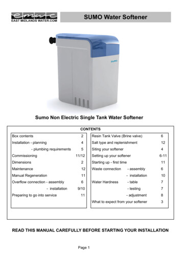
MODEL 5600SE DownflowValve Wiring DiagramCB1 - 5600SE Circuit BoardVDM - Valve Drive MotorEM - Electronic Flow Meter (Optional)SW1 - Homing SwitchSW2 - Step SwitchHCAM - Homing CamDFSCAM - Downflow Step CamPage 22Printed in U.S.A.
MODEL 5600SE DownflowService InstructionsA. TO REPLACE BRINE VALVE, INJECTORS,AND SCREEN1. Turn off water supply to conditioner:a. If the conditioner installation has a “threevalve” by-pass system, first open the valve inthe by-pass line, then close the valves at theconditioner inlet and outlet.b. If the conditioner has an integral by-passvalve, put it in the by-pass position.c. If there is only a shut-off valve near theconditioner inlet, close it.2. Relieve water pressure in the conditioner bystepping the control into the backwash positionmomentarily. Return the control to the serviceposition.3. Unplug electrical cord from outlet.4. Disconnect brine tube and drain line connectionsat the injector body.5. Remove the two injector body mounting screws.The injector and brine module can now beremoved from the control valve. Remove anddiscard brine body O-rings.6A. To replace brine valve.1. Pull brine valve from injector body, alsoremove and discard O-ring at bottom of brinevalve hole.2. Apply silicone lubricant to new O-ring andreinstall at bottom of brine valve hole.3. Apply silicone lubricant to O-ring on newvalve assembly and press into brine valvehole, shoulder on bushing should be flushwith injector body.6B. To replace injectors and screen.1. Remove injector cap and screen, discard Oring. Unscrew injector nozzle and throat frominjector body.2. Screw in new injector throat and nozzle, besure they are sealed tightly. Install a newscreen.3. Apply silicone lubricant to new O-ring andinstall around oval extension on injector cap.7. Apply silicone lubricant to three new O-rings andinstall over three bosses on injector body.8. Insert screws thru injector cap and injector. Placethis assembly thru hole in timer housing and intomating holes in the valve body. Tighten screws.9. Reconnect brine tube and drain line.10. Return by-pass or inlet valving to normal serviceposition. Water pressure should now be appliedto the conditioner, and any by-pass line shut off.11. Check for leaks at all seal areas. Check drainseal with the control in the backwash position.12. Plug electrical cord into outlet.13. Set time of day and cycle the control valvemanually to assure proper function. Make surecontrol valve is returned to the service position.14. Make sure there is enough salt in the brine tank.15. Start regeneration cycle manually if water is hard.B. TO REPLACE TIMER1. Follow Steps A.1 through A.3.2. Remove the control valve back cover. Removethe control valve front cover. Disconnect themeter dome signal wire from the front cover andfeed it back through the control.3. Remove screw and washer at drive yoke.Remove timer mounting screws. The entire timerassembly will now lift off easily.4. Put new timer on top of valve. Be sure drive pinon main gear engages slot in drive yoke.5. Replace timer mounting screws. Replace screwand washer at drive yoke. Replace meter signalwire.6. Return by-pass or inlet valving to normal serviceposition. Wat
resulted from the installation. Once clean, close the water tap. 11. Place the by-pass in service position and let water flow into the mineral tank. When water flow stops, slowly open a cold water tap nearby and let run until the air is purged from the unit. Then close tap. 12. Plug the valve into an approved power source.