Transcription
User ManualThermo Scientific HERAfreezeHFU B Series -86C ULT Upright FreezerOperating and Maintenance Manual 7038931 Rev. 20Visit us online to register your warrantywww.thermoscientific.com/labwarranty
PrefaceImportant installer and user information:A redundant temperature sensing device has been included in this ULT freezer.This device is a type “T” thermocouple. For convenient access, the thermocouple (Figure 1-3) terminates in an interconnect jack (Figure 1-5) behind the basefront cover. (May be located differently in chests. See Section 1.) It is stronglyrecommended that this thermocouple be attached to a redundant 24 hour 7day monitoring system with alarm capabilities. Connecting the sensor to amonitoring and alarm system separate from the freezer provides the utmost inproduct safety, should the integral system fail. Models CoveredPacking oltage(cu. 380520Neoprene Cap2HFU240BA13120/605100161/4-20 x 5-1/2” Bolt2HFU320BA17120/60195763Retaining Clip1HFU320BD17208-230/60370563Remote /60HFU600BV28230/50MANUAL NUMBER 7038931204063411/03/17Updated exploded drawingsbpg194172810/04/17Added door operation pg 1-5bpg18315148/25/17Updated drawing 195964-90-1bpg17413706/06/17Updated BUS board infobpg1641348/41159/405435/17/17Fixed operating range temp, D-volt rating, added F-gas statementbpg1641346/413475/17/17Removed SS and AS400 model numbersbpg1531061/FR-28339/19/16Updated door gasket in 902-200-1 on pgs 7-1 and 7-2.ccsThermo ScientificHFU B Seriesi
PrefaceCAUTIONContains Parts and AssembliesSusceptible to Damage byElectrostatic Discharge (ESD)Important Read this instruction manual. Failure to read, understand and follow the instructions in this manualmay result in damage to the unit, injury to operating personnel, and poor equipment performance. Caution All internal adjustments and maintenance must be performed by qualified service personnel. Material in this manual is for information purposes only. The contents and the product it describes are subjectto change without notice. Thermo Fisher Scientific makes no representations or warranties with respect to thismanual. In no event shall Thermo be held liable for any damages, direct or incidental, arising out of or related tothe use of this manual.The -86 C Freezers (see page i for specific list of models) described in this manual are high performance unitswhich can be used for research and in situations that directly support medical applications. When these productsare used to support a medical application, it is an accessory to a medical device and is therefore considered as amedical device in its own right by the regulatory body (e.g. FDA).This product is intended for use: As cold storage in research use. As a medical device for diagnostic use (storage of samples not intended to be re-introduced to human body).Intended UseThis product is intended for use as a General Purpose Laboratory Freezer for storing samples or inventorybetween -50 and -86C.This unit is not intended for use in an explosive environment, nor to be used for the storage of flammableinventory. This unit is not intended for use in a Class II medical application as defined by Title 21 of theFederal Code of Regulations.Registration: This medical application is considered a Class I medical device by the FDA. This product isclassified as product code – JRM, regulation number 862.2050 and is considered a Class 1 device, 510(K)exempt. 2017 Thermo Fisher Scientific. All rights reserved.iiHFU B SeriesThermo Scientific
PrefaceImportant operating and/or maintenance instructions. Read the accompanying text carefully.Potential electrical hazards. Only qualified persons should perform procedures associated with thissymbol.Equipment being maintained or serviced must be turned off and locked off to prevent possible injury.Extreme temperature hazards, hot or cold. Use special handling equipment or wear special, protectiveclothing.WEEE Compliance: Thermo Fisher Scientific has contracted with companies for recycling/disposal ineach EU Member State. For further information, send an email to weee.recycle@thermofisher.com. Always use the proper protective equipment (clothing, gloves, goggles, etc.) Always dissipate extreme cold or heat and wear protective clothing. Always follow good hygiene practices. Each individual is responsible for his or her own safety.Thermo ScientificHFU B Seriesiii
PrefaceDo You Need Information or Assistance onThermo Scientific Products?If you do, please contact us 8:00 a.m. to 6:00 p.m. (Eastern Time) isher.comwww.unitylabservices.comDirectToll Free, U.S. and CanadaFAXInternet Worldwide Web Home PageTech Support Email AddressCertified Service Web PageOur Sales Support staff can provide information on pricing and give you quotations. We cantake your order and provide delivery information on major equipment items or makearrangements to have your local sales representative contact you. Our products are listed on theInternet and we can be contacted through our Internet home page.Our Service Support staff can supply technical information about proper setup, operation ortroubleshooting of your equipment. We can fill your needs for spare or replacement parts orprovide you with on-site service. We can also provide you with a quotation on our ExtendedWarranty for your Thermo Scientific products.Whatever Thermo Scientific products you need or use, we will be happy to discuss yourapplications. If you are experiencing technical problems, working together, we will help youlocate the problem and, chances are, correct it yourself.over the telephone without a servicecall.When more extensive service is necessary, we will assist you with direct factory trainedtechnicians or a qualified service organization for on-the-spot repair. If your service need iscovered by the warranty, we will arrange for the unit to be repaired at our expense and to yoursatisfaction.Regardless of your needs, our professional telephone technicians are available to assist youMonday through Friday from 8:00 a.m. to 6:00 p.m. Eastern Time. Please contact us bytelephone or fax. If you wish to write, our mailing address is:Thermo Fisher Scientific (Asheville) LLC401 Millcreek Road, Box 649Marietta, OH 45750International customers, please contact your local Thermo Scientific distributor.ivHFU B SeriesThermo Scientific
Table of ContentsThermo ScientificSection 1Installation and Start-up . . . . . . . . . . . . . . . . . . . . . . . . . . . . . . . . . . . . . 1-1Control Panel Keys, Displays, Indicators . . . . . . . . . . . . . . . . . . . . . . 1-4Operation of the Keypad . . . . . . . . . . . . . . . . . . . . . . . . . . . . . . . . . . 1-5Install Freezer . . . . . . . . . . . . . . . . . . . . . . . . . . . . . . . . . . . . . . . . . . .1-5Choose Location . . . . . . . . . . . . . . . . . . . . . . . . . . . . . . . . . . . . . . . 1-5Door Operation . . . . . . . . . . . . . . . . . . . . . . . . . . . . . . . . . . . . . . . 1-5Install Wall Bumpers . . . . . . . . . . . . . . . . . . . . . . . . . . . . . . . . . . . .1-6Install Shelves . . . . . . . . . . . . . . . . . . . . . . . . . . . . . . . . . . . . . . . . . 1-6RS-232 Communication . . . . . . . . . . . . . . . . . . . . . . . . . . . . . . . . . 1-6Remote Alarm Contacts . . . . . . . . . . . . . . . . . . . . . . . . . . . . . . . . . 1-7Attach Power Cord . . . . . . . . . . . . . . . . . . . . . . . . . . . . . . . . . . . . . 1-8Connect Unit to Electrical Power . . . . . . . . . . . . . . . . . . . . . . . . . . 1-8Freezer Start-Up . . . . . . . . . . . . . . . . . . . . . . . . . . . . . . . . . . . . . . . . .1-8Set Operating Temperature . . . . . . . . . . . . . . . . . . . . . . . . . . . . . . .1-9Set High Temperature Alarm . . . . . . . . . . . . . . . . . . . . . . . . . . . . . 1-9Set Low Temperature Alarm . . . . . . . . . . . . . . . . . . . . . . . . . . . . . 1-10Run Mode . . . . . . . . . . . . . . . . . . . . . . . . . . . . . . . . . . . . . . . . . . . . 1-10Section 2Calibrate . . . . . . . . . . . . . . . . . . . . . . . . . . . . . . . . . . . . . . . . . . . . . . . . . . . . 2-1Calibrate Control Probe . . . . . . . . . . . . . . . . . . . . . . . . . . . . . . . . . . .2-1Temperature Stabilization Periods . . . . . . . . . . . . . . . . . . . . . . . . . .2-1Section 3Alarms . . . . . . . . . . . . . . . . . . . . . . . . . . . . . . . . . . . . . . . . . . . . . . . . . . . . . . 3-1High Stage System Failure . . . . . . . . . . . . . . . . . . . . . . . . . . . . . . . . . 3-2Probe Failure Alarm . . . . . . . . . . . . . . . . . . . . . . . . . . . . . . . . . . . . . . 3-2Section 4Maintenance . . . . . . . . . . . . . . . . . . . . . . . . . . . . . . . . . . . . . . . . . . . . . . . . 4-1Clean Air Filter . . . . . . . . . . . . . . . . . . . . . . . . . . . . . . . . . . . . . . . . . 4-1Clean Condenser . . . . . . . . . . . . . . . . . . . . . . . . . . . . . . . . . . . . . . . . 4-1Clean Water-cooled Condenser . . . . . . . . . . . . . . . . . . . . . . . . . . . .4-2Clean Door Gasket . . . . . . . . . . . . . . . . . . . . . . . . . . . . . . . . . . . . . . 4-2Defrost Chamber . . . . . . . . . . . . . . . . . . . . . . . . . . . . . . . . . . . . . . . . 4-3Prepare Unit for Storage . . . . . . . . . . . . . . . . . . . . . . . . . . . . . . . . . . 4-3Long Term Storage with Water-cooled Condenser . . . . . . . . . . . . . 4-4Vacuum Relief Port . . . . . . . . . . . . . . . . . . . . . . . . . . . . . . . . . . . . . 4-4Check Battery(s) . . . . . . . . . . . . . . . . . . . . . . . . . . . . . . . . . . . . . . . . 4-5Replace Battery(s) . . . . . . . . . . . . . . . . . . . . . . . . . . . . . . . . . . . . . . . 4-6PREVENTIVE MAINTENANCE . . . . . . . . . . . . . . . . . . . . . . . . .4-7HFU B Seriesv
Table of ContentsviHFU B SeriesSection 5Factory Installed Options . . . . . . . . . . . . . . . . . . . . . . . . . . . . . . . . . . . . . .5-1Back Up System (BUS) - P/N 1950533, 1950535 . . . . . . . . . . . . . . 5-1Install Vent Stack, Solenoid and Injection Assembly . . . . . . . . . . . .5-1Install Temperature Probe . . . . . . . . . . . . . . . . . . . . . . . . . . . . . . . .5-3Connect Probe/Solenoid Harness . . . . . . . . . . . . . . . . . . . . . . . . . . 5-3BUS Control Panel . . . . . . . . . . . . . . . . . . . . . . . . . . . . . . . . . . . . . 5-5Configure Optional BUS (Back-Up System) . . . . . . . . . . . . . . . . . .5-7Set Optional BUS Set Point . . . . . . . . . . . . . . . . . . . . . . . . . . . . . . 5-7Test BUS Operation . . . . . . . . . . . . . . . . . . . . . . . . . . . . . . . . . . . . 5-8Clean Vent Stack . . . . . . . . . . . . . . . . . . . . . . . . . . . . . . . . . . . . . . . . 5-8Disconnect Fitting Asm. and Transfer Hose . . . . . . . . . . . . . . . . . . . 5-8Chart Recorder . . . . . . . . . . . . . . . . . . . . . . . . . . . . . . . . . . . . . . . . . 5-8Installing the Chart Paper . . . . . . . . . . . . . . . . . . . . . . . . . . . . . . . . 5-9Change Recorder Temperature Range . . . . . . . . . . . . . . . . . . . . . . .5-9Recorder Calibration . . . . . . . . . . . . . . . . . . . . . . . . . . . . . . . . . . . .5-9Water-cooled Condenser . . . . . . . . . . . . . . . . . . . . . . . . . . . . . . . . .5-10Water Connections . . . . . . . . . . . . . . . . . . . . . . . . . . . . . . . . . . . . 5-12Section 6Specifications . . . . . . . . . . . . . . . . . . . . . . . . . . . . . . . . . . . . . . . . . . . . . . . 6-1Section 7Spare Parts . . . . . . . . . . . . . . . . . . . . . . . . . . . . . . . . . . . . . . . . . . . . . . . . . 7-1Section 8Refrigeration Schematics . . . . . . . . . . . . . . . . . . . . . . . . . . . . . . . . . . . . .8-1Section 9Electrical Schematics . . . . . . . . . . . . . . . . . . . . . . . . . . . . . . . . . . . . . . . . 9-1Section 10Warranty . . . . . . . . . . . . . . . . . . . . . . . . . . . . . . . . . . . . . . . . . . . . . . . . . . . 10-1AppendixHandling Liquid Nitrogen . . . . . . . . . . . . . . . . . . . . . . . . . . . . . . . . . . . . . A-1Handling Liquid CO2 . . . . . . . . . . . . . . . . . . . . . . . . . . . . . . . . . . . . . . . . . . B-1First Aid . . . . . . . . . . . . . . . . . . . . . . . . . . . . . . . . . . . . . . . . . . . . . . . . . . . . .C-1Thermo Scientific
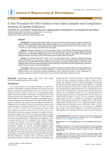
Section 1Installation and Start-upControl PanelOptional Back UpSystem ControlsTemperatureRecorder(Optional)Figure 1-1. Freezer Front View ComponentsThermo Scientific Control panel - keypad, displays and indicators BUS (Optional Back Up System) control panel Optional temperature recorder or dataloggerHFU B Series1-1
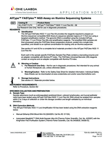
Section 1Installation and Start-UpWall Bumper(pre-tapped holes)Optional Back-upSystem ConnectionsRemote AlarmContactsPower Switch(mainsdisconnect)Power InletFigure 1-2. Freezer Rear View Components Remote alarm contacts Power inlet for power cord connection Optional BUS connections for probe and solenoid Power switch (mains disconnect)ShelfBracketOptional Miscellaneous Accessories ProbeOptional - Recorder Probe/Datalogger ProbeSealant(Caution: This is a critical seal.Seal must be maintained.)Control RTD/Redundant Type TThermocouple ProbeFigure 1-3. Chamber Probe(s)1-2HFU B SeriesThermo Scientific
Section 1Installation and Start-UpVacuumRelief PortChamberProbe CoverFigure 1-4. Vacuum Relief and Probe Cover Location Vacuum relief port - pressure equalization port Probe cover - houses control, optional recorder, datalogger, ormiscellaneous accessory probes Battery mounting bracket(s)Battery powerswitchToremove filterThermocoupleinterconnect jackBattery mountingbracketOFreezer batteryand optional BUS batteryFigure 1-5. Battery(s) location and switchThermo Scientific Battery power switch (freezer and BUS) Freezer battery Optional BUS battery Freezer filter locationHFU B Series1-3
Section 1Installation and Start-UpTemperatureDisplayModeKeyFigure 1-6. Control PanelControl Panel Keys,Displays, IndicatorsOperation of theKeypadSilenceAlarmIndicator KeyUp and DownArrowsAlarmPanelEnter Key Temperature Display - Displays temperature in degrees Celsius. Mode Select Switch - Used to select Run, Set Temperature, Set HighAlarm, Set Low Alarm, Calibrate, Backup. Alarm Indicator - Light pulses on/off during an alarm condition of thecabinet. Silence - Silences the audible alarm. See Section 4 for alarm ringbacktimes. Alarm Panel - indicates the current alarm condition. Up and Down Arrows - Increases or decreases values, toggles betweenchoices. Enter - Stores the value into memoryHFU B Series freezer has five basic modes which allow freezer setup andoperation. Press the Mode key to scroll through the mode selections.Up Arrow: Increases or toggles the parameter value.Enter: Must press Enter key to save to memory all changedvalues.Down Arrow: Decreases or toggles the parameter value.Silence Key: Press to silence the audible alarm. See Section4 for alarm ringback times.1-4HFU B SeriesThermo Scientific
Section 1Installation and Start-UpInstall FreezerNote If tipped more than 45 , allow the unit to sit upright for 24 hoursbefore start up. To remove the freezer from the pallet, use a 7/16" wrench to remove allthe bolts securing the shipping bracket to the pallet.Remove the shipping bracket. Remove the ramp boards from the palletand place the slotted end over the ramp brackets on the pallet. Thesupport blocks on the ramps will be facing down. Before moving thefreezer, make sure the casters are unlocked and moving freely. Align thecaster with the ramp boards. Use adequate personnel to roll the freezer offthe pallet.Choose LocationThe freezer can be easily pushed to the desired approved location,described below. If necessary, the doors and lower front panel may beopened to move the unit through tight openings. When the freezer is inposition, set the front caster brakes.Note The freezer must not be moved with the product load inside. Note For proper ventilation and airflow, a minimum clearance of 5” at therear and top and a clearance of 8” on the side of the freezer is required.Allow adequate space in the front of the freezer for door opening. Locate the freezer on a firm, level surface in an area with an ambienttemperature between 18 C and 32 C. Provide ample room to reach themains disconnect switch (power switch) located on the rear of the freezer.Door OperationUpright freezer models are equipped with an advanced assemblyspecifically designed for ultra-low temperature freezers.Features include:Thermo Scientific One-hand operation A front-accessible lock Hasps for a standard padlock to provide additional security. Length ofthe shackle must be between ¾ inch (1.9 cm) and 1½ inch (3.8 cm). Durable construction for reliable operation and safe product storage.HFU B Series1-5
Section 1Installation and Start-UpInstall Wall BumpersThe parts bag, located inside the cabinet, contains the following parts.Table 1-1. Parts bagQuantityStock #DescriptionPurpose25100161/4-20 x 5-1/2” BoltWall Bumper2380520Neoprene CapCap ProtectorInstall the bolts into the pre-tapped holes on the back of the compressorsection. Install a neoprene cap on each bolt. Refer to Figure 1-2 for thelocations of the pre-tapped holes.Install ShelvesInstall the shelf clips into the shelf pilasters (front and back) at the desiredshelf level. Install the shelves in the cabinet onto the clips.Note Maximum shelf load is 100 lbs (45.4 kg) per shelf. Note On units having the optional 5 inner door option, refer to theinstructions accompanying the inner door kit. RS-232 CommunicationThe Model 8900 Series freezer has a data communications interface. Thefactory default setting is RS-232.The wiring identification for theinterface is shown in Figure 1-7. Onenine pin, sub "D" style connector islocated on the back of the freezer. SeeFigure 1-2 for the location of theconnector on the freezer.Figure 1-7. RS-232 InterfaceThe freezer transmits temperature information every 60 minutes. Astandard DB9 serial extension cable can be used to connect the freezer to aserial device. Some serial devices may require a null modem adapter.Data format:Baud . . . . . . . . . . . . . . . . . . . . . . . . . . . . . . . . 1200Data bits . . . . . . 8 (7 bit ASCII with leading zero)Start bits . . . . . . . . . . . . . . . . . . . . . . . . . . . . . . . . 1Stop bits . . . . . . . . . . . . . . . . . . . . . . . . . . . . . . . . 2Parity . . . . . . . . . . . . . . . . . . . . . . . . . . . . . . . noneThe data transfer sequence is transmitted in the following format. X refersto numerical temperature data.(NUL) (-) XXX (SP) C (SP) (Error Message) (SP) (LF) (CR) (EOT) (SP)1-6HFU B SeriesThermo Scientific
Section 1Installation and Start-UpRS-232 Communication(continued)In the event of a CNTRLFAIL, Er07, or the control probe is out of rangeerror, the numerical temperature data (XXX) in the transmission would bereplaced by T ERR.If no alarm condition exists, spaces will be sent. A total of 20 characterswill be sent.SP - SpaceLF - Line feedCR - Carriage returnEOT - End of text (4)NUL - Null character (00)If an alarm condition does exist, “Error Message” in the protocol will bereplaced by the following:UNDERTEMP (temperature above the low alarm setpoint)OVERTEMP (temperature below the high alarm setpoint)PWRFAIL (AC power failure)CNTRLFAIL (Control probe failure)Er07 (micro failure)HSHX FAIL (Heat exchanger failure)HOT COND (Hot condenser)Remote Alarm ContactsSee Figure 1-2 for the location of the remote alarm contacts. The remotealarm connector is located in the parts bag provided with the manual. Itmust be installed if connecting the freezer to an alarm system. Afterinstalling the wiring from the alarm system to the connector, install theconnector to the freezer microboard and secure with the two screwsprovided. The remote alarm provides a NO (normally open) output, a NCnormally closed) output and COM (common). The contacts will trip on apower outage and high temperature or low temperature alarms. They willalso trip on high stage, control probe or microboard failures.Figure 1-8 shows the remote contacts in alarm state.IMPORTANT USER INFORMATIONCAUTION! Stored product should be protectedby a redundant 24 hour/day monitoring systemwith alarm capability. An interconnect jack andthermocouple are installed for centralizedmonitoring, should on-board system fail.Figure 1-8. Remote Alarm ContactsThermo ScientificHFU B Series1-7
Section 1Installation and Start-UpAttach Power CordInsert the power cord into thepower inlet module. Place theretaining bracket (P/N 195763)over the connector. Tightenretaining screws to secure.Figure 1-9. Power Cord ConnectionConnect Unit to ElectricalPowerSee the serial tag on the side of the unit for electrical specifications or referto the electrical schematics in this manual.The freezer should be operated on a dedicated grounded service. Check thevoltage rating on the serial tag of the unit and compare it with the outletvoltage. Then, with the power switch turned off, plug the line cord intothe wall outlet.First, turn on the freezer power switch. Then open the lower front door bygrasping the bottom left corner. Locate the battery switch (Figure 1-5) andturn it to Standby mode ( ). During initial freezer start-up, the systembattery may require charging and the Low Battery indicator mayilluminate.Note Ensure the battery switch is turned to Standby mode ( ). Therechargeable batteries require 36 hours to charge at initial start-up. A “LowBattery” alarm may occur until the batteries are fully charged. Should apower failure occur during the initial start-up period, the electronics willhave limited operation. Freezer Start-UpWith the freezer properly installed and connected to power, system setpoints can be entered. The following set points can be entered in Settingsmode: Control temperature, high temperature alarm set point, lowtemperature alarm set point, and (optional) BUS set point. Default settingsare shown in the table below.Table 1-2. Default Settings1-8HFU B SeriesDefault SettingsTemperatureControl Set Point-80 CHigh Temperature Alarm-70 CLow temperature alarm-90 COptional BUS Set Point-60 CThermo Scientific
Section 1Installation and Start-UpFreezer Start-Up(continued)Note If the set point is changed and the low and high temperature alarmsare set 10 from the set point, the alarm set points will be adjustedautomatically to maintain a distance of at least 10 from set point. Caution If the factory installed option water-cooled condenser is present,do not turn the freezer on without water connected and flowing. Damageto the refrigeration system could occur within 5 minutes if water is notconnected and flowing on unit start-up. Refer to Section 5. Set OperatingTemperatureHFU B Series freezers have an operating temperature range of -50 C to-86 C, depending on ambient temperature. The freezer is shipped fromthe factory with a temperature set point of -80 C. To change the operatingtemperature set point:1. Press the Mode key until the Set Temperature indicator lights.2. Press the up/down arrow key until the desired temperature set point isdisplayed.3. Press Enter to save the set point.4. Press the Mode key until the Run indicator lights for Run modeIf no keys are pressed, the freezer will automatically return to RUN modeafter 5 minutes.Note If the set point is changed and the low temperature and hightemperature alarms are set 10 from the set point, the alarm set points willbe adjusted automatically to maintain a distance of at least 10 from setpoint. Set High TemperatureAlarmThe high temperature alarm will activate an audible/visual warning whenthe freezer chamber temperature has reached or exceeded the hightemperature alarm set point.To set the high temperature alarm set point:1. Press the Mode key until the Set High Alarm indicator lights.2. Press the up or down arrow key until the desired high temperaturealarm set point is displayed.3. Press Enter to save the setting.Thermo ScientificHFU B Series1-9
Section 1Installation and Start-UpSet High TemperatureAlarm (continued)4. Press the Mode key until the Run indicator lights for Run modeIf no control keys are pressed, the freezer will automatically return to RUNmode after 5 minutes.Note The high alarm set point must be set at least 5 C from the controlset point. Note At initial start-up, the high temperature alarm is disabled until thecabinet reaches set point or 12 hours elapse. Set Low TemperatureAlarmThe low temperature alarm will activate an audible/visual warning whenthe freezer chamber temperature has reached or decrease below the lowtemperature alarm set point.To set the low temperature alarm set point:1. Press the Mode key until the Set Low Alarm indicator lights.2. Press the up or down arrow key until the desired low temperaturealarm set point is displayed.3. Press Enter to save the setting.4. Press the Mode key until the Run indicator lights for Run modeIf no control keys are pressed, the freezer will automatically return to RUNmode after 5 minutes.Note The low alarm set point must be set at least 5 C from the control setpoint. Run ModeRun mode is the default mode for the freezer. This mode displays thecabinet temperature on the temperature display under normal operatingconditions. In addition, the Run mode allows display of the high stage heatexchange temperature.This information scrolls by pressing the up or down arrow keys. Thedisplay returns to the operating temperature in 10 seconds if no keys arepressed.1-10HFU B SeriesThermo Scientific
Section 2CalibrateOnce the freezer has stabilized, the control probe may need to becalibrated. Calibration frequency is dependent on use, ambient conditionsand accuracy required. A good laboratory practice would require at least anannual calibration check. On new installations, all parameters should bechecked after the stabilization period.Caution Before making any calibration or adjustments to the unit, it isimperative that all reference instruments be properly calibrated. Calibrate ControlProbePlug a type T thermocouple reader into the receptacle located inside thelower door (see Figure 1-5). Compare the control temperature set point tothe temperature of the measuring device.1. Press the Mode key until the Calibrate indicator lights.2. Press up/down arrow to match the display to calibrated instrument.3. Press Enter to store calibration.4. Press the Mode key to return to Run mode.Temperature StabilizationPeriodsStartup - Allow 12 hours for the temperature in the cabinet to stabilizebefore proceeding.Already Operating - Allow at least 2 hours after the display reaches setpoint for temperature to stabilize before proceeding.During calibration, the temperature display will not be available. If no keys are pressed for approximately five minutes while in calibrationmode, the system will reset to Run mode.Thermo ScientificHFU B Series2-1
Section 3AlarmsThe HFU B Series freezer alarms are displayed on the freezer controlpanel. When an alarm is active, the indicator next to the alarm descriptionwill light and there will be an audible alarm. Press the Silence key todisable the audible alarm for the ringback period. The visual alarm willcontinue until the freezer returns to a normal condition. The alarms aremomentary alarms only. When an alarm condition occurs and then returnsto normal, the freezer automatically clears the alarm condition.Table 3-1. Alarm IndicatorsDescriptionDelayRingbackRelayPower Failure1 min.15 min.YesHigh Temperature Alarm1 min.15 min.YesLow Temperature Alarm1 min.15 min.YesProbe Failure see Section 31 min.15 min.NoDoor Open1 min.15 min.NoWrong Power0 min.noneYesLow Battery*1 min.8 hoursNoLow BUS Battery (optional)1 min.15 min.NoHot Condenser1 min.noneNoHigh Stage Failure0 min.15 min.YesMicro Board Failure0 min.15 min.YesAll alarm delays and ringback times are 30 seconds.* The automatic battery test runs immediately on power-up, then every 8 hours thereafter.Thermo ScientificHFU B Series3-1
Section 3Alarms3-2High Stage SystemFailureThe "high stage system failure" condition is created when the high stagecompressor and fans run for 30 minutes and are not capable of cooling theinterstage heat exchanger to the proper temperature. Under this condition,the high stage compressor and fans will turn off after 30 minutes and anaudible and visual alarm will occur. The audible alarm can be silenced andwill ring back every 15 minutes.Probe Failure AlarmThe microprocessor in HFU B Series freezers continually scans all probesincluding the control probe, heat exchanger probe and condenser probe toensure that they are operating properly. Should an error be detected, the"Probe Failure" alarm will occur as described above. If an error is detectedwith the control probe, the high and low stage compressors will runcontinuously. As a result, the cabinet temperature will decrease until itreaches the lowest temperature that the refrigeration system can maintain.If an error is detected with the heat exchanger probe, the freezer will cycleproperly at its temperature set point using a 5 minute step start betweenthe high and low stage compressors. If an error is detected with thecondenser probe, there is no impact on the performance of the freezer;however, the hot condenser alarm may also occur. Contact the TechnicalServices department or your local distributor.HFU B SeriesThermo Scientific
Section 3AlarmsErrorNotesEr00Name: Improper model selected.Description: Indicates that DIP SW3 has not selected a proper model or can’t be accessed properly.Response: Display shows “Er00” and will not start-up until a proper model is selected. Contact Technical Services.ErA1ErC1Erd1ErE1ErF1E
HFU B Series -86C ULT Upright Freezer Operating and Maintenance Manual 7038931 Rev. 20. Thermo Scientific Preface HFU B Series i Part Number Description Qty 122005 Key 2 . service.led.marietta@thermofisher.com Tech Support Email Address www.unitylabservices.com Certified Service Web Page