Transcription
Leer, Inc.206 Leer Street, P.O. Box 206New Lisbon, WI 539501-800-766-5337www.leerinc.comSTORAGE FREEZERINSTALLATION, OPERATION, AND SERVICEMANUALWARNING: This product can expose you to chemicalsincluding nickel, which is known to the State of California tocause cancer (For more information go towww.p65warnings.ca.gov)1070501 11/2020
Table of ContentsStart-UP. 3Storage and Transportation: . 3Packaging: . 3Installation. 3Freezer Placement: . 3NSF Installation: . 3Freezer Leveling: . 3Electrical: . 3Condensate Evaporator: . 4Operation. 4Electronic Controls: Digital Display:. 4Operating Mode Display: . 4Electronic Control Operation: . 5Auto-Defrost Control: . 5Possible Displayed Alarm Codes: . 5Loading Product: . 5Condenser Fan Pressure Switch:. 6Maintenance . 6Cleaning the Freezer: . 6Cleaning Door Gaskets: . 6Cleaning Condenser Coils: . 6Defrosting the Freezer: . 6Auto-Defrost Electronic Control: . 7Solid Door Models and Maintenance: . 7Hinge Spring Tension: . 7Electronic Control- AD Wiring Diagram W/Relay: . 10Notes: . 11Warranty: . 122
Start-UPStorage and Transportation:The freezer should be stored and transported in anupright position. It is not recommended to tilt thefreezer. If the freezer is tilted beyond 45 degrees ofvertical, oil may drain from the compressor causingpremature failure.Do Not stack merchandisers on top of one anotherdue to risk of falling. Falling merchandisers couldresult in damaged units or serious injuries. It isrecommended to use warehouse racking design toaccommodate the weight of the merchandisers andprevent falling.Packaging:Prior to installation, the outer packaging on thefreezer will need to be removed. The majority of thepackaging materials can be recycled and disposedof in an environmentally friendly manner. Thewooden skid is secured to the underside ofmerchandiser with hex-headed screws and willrequire the use of a 3/8" hex-socket for screwremoval.device to raise the merchandiser from the ground.Allow enough room to get the full kit under the skidplate. DO NOT TIP THE MERCHANDISERbeyond 45 of vertical as mentioned in the Storageand Transportation section of this manual. Insertthe stem of the leveling kit into the bottom of theskid plate. Lower the merchandiser into positionwhile maintaining the 6-inch required NSFclearance.Freezer Leveling:The merchandiser installation location should havea solid, level base. If the merchandiser is exhibitinga slight forward lean, the front of the cabinet shouldbe blocked to bring the cabinet to a level position.On auto-defrost models, a forward lean maynegatively affect proper draining of the unit coolerassembly during the defrost cycle.Leveling kits are available for use on most cabinetmodels. Contact the Merchandiser SalesDepartment for more information.InstallationFull leveling kit shown,inserted into the skidplate of themerchandiser.Note: Leer Ice Merchandisers are commercial indesign and not intended for residential useFreezer Placement: When placing the freezer,allow a minimum of 3 inches of air space from allsurfaces of the cabinet and any surroundingstructures. This air space allows for air flow overthe surface of the cabinet, thus reducingcondensation and aid in the drying of these surfaces.On outdoor auto-defrost models, the 3-inch spacebehind the freezer will also help ensure that theevaporator drain tube, which exits the back wall, isnot being restricted during the defrost cycle.NSF Installation:Most merchandisers can be special ordered withNSF certification. NSF merchandisers are suppliedwith leveling kits packaged inside. These kits arerequired by NSF to maintain a 6-inch clearancefrom bottom of unit to the ground. This kit must beinstalled on location. To install, use a proper liftingElectrical:Warning! Component parts shall only bereplaced with like components. Electrical andservicing should be done by licensedprofessionals. Disconnect power beforeperforming service. Certain models containmultiple voltages. Leer does not assumeresponsibility for any damage to people or thingsderiving from violation, improper use or in anycase not in compliance with Leer’s instructions.The freezer must be plugged into a dedicated andproperly grounded 115V/60hz/1Ph circuit with acircuit fuse or breaker rated at a 15 or 20 Ampsdepending on model. The electrical service3
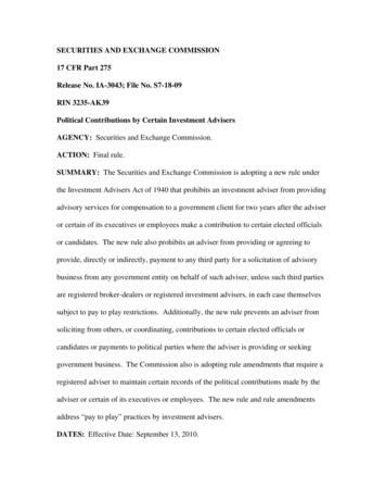
connections to the freezer must be compliant withnational electric code and local codes that mayapply. DO NOT use extension cords. The 20 Ampplug configuration, that some models come with,should NOT be removed. Some models areequipped with a main power switch. If so equipped,make sure the switch is in the OFF position beforeplugging the freezer into the outlet. Plug the freezerpower cord into the lower receptacle of theelectrical outlet. Turn the switch if equipped intothe ON position. After a few seconds delay, thecompressor and the condenser fans should start. Thelight fixture should start immediately when power isapplied. The evaporator fans are set to operate onlyif the evaporator coil temperature is 75 . Thecondensing unit will continue to run until the airtemperature in the cabinet reaches -12 F.WARNING: Operating more than one appliance onthe same circuit may result in voltage fluctuationswhen both appliances are operating simultaneously.This voltage fluctuation may cause the circuitbreaker to trip and/or may cause voltage drops. As aresult, the power to the freezer may be interruptedand freezing performance can be adversely affectedwhich may cause equipment damage and /orproduct loss. Voltage supply to the merchandisermust not vary more than 10% of the normal 115V.Information regarding the electrical voltage andfrequency being supplied to the merchandiser canbe found on the merchandiser’s serial data platetypically located at the upper left corner of themerchandiser’s interior. Information regarding themaximum fuse/circuit breaker size required for thespecific model is available from the condensing unitdata plate.least 1 inch of air space between the back surface ofthe condensate evaporator housing and any wallsurface behind the cabinet which allows for heatdissipation away from the surface of the wall. Themain power cord should also be routed to avoidpinching.Note: Do not operate an indoor auto-defrostmerchandiser without having a condensateevaporator assembly installed under the evaporatordrain tube exiting the back wall of the cabinet.Failure to install this assembly will result in waterdraining directly onto the floor during the defrostcycle. This may result in water damage to the floorand create a hazardous slip condition in the areasurrounding the freezer.Figure 1: Condensate Evaporator InstallationOperationElectronic Controls: Digital Display:Manual DefrostDefrost EnabledCompressor EnabledCondensate Evaporator: Indoor auto-defrostmodels are supplied with a condensate evaporatorheater assembly which is packaged with instructionsand shipped inside the freezer. It will require simpleinstallation by the consumer (see Figure 1). Aseparate copy of this instruction sheet is suppliedwith the condensate evaporator assembly. Thecondensate evaporator assembly contains a drip panto collect water generated by the freezer’s defrostcycle and a heat element to evaporate the water.Once energized, the heat element in the condensateevaporator assembly is continuously generatingheat. The freezer is to be placed so that there is atSetTemperature & SettingsOperating Mode Display: Snowflake “ON” – compressor enabled inrun cycle; control displays current cabinettemperature.Snowflake “Flashing” – anti short cycledelay enabled to protect the compressorfrom trying to start too frequently.4
Melting Snowflake “ON” – defrost inprogress, control displays the letters “DE” To view the control’s programmed “SetPoint” (cut-out temperature): press andrelease the “Set Key.” To initiate a manual defrost cycle: press andhold the “Manual Defrost Key” for morethan 2 seconds.Note: Manual Defrost will not initiate unless theunit is at standard operating temperatures.Electronic Control Operation:The electronic control combines the functions ofboth the mechanical thermostat and defrost timerinto a single control. The control also offers theconsumer the capability of monitoring theoperational status of the freezer via the icon anddigital temperature display (located on the face ofthe control). The controls have been programmedby Leer to operate the freezer within the designparameters of the refrigeration system. The setpoint (cut-out) has programmed parameters for -12 F, with a differential of 6 F. Should the user desireto alter the Set-Point, the new set-points should notexceed /- 4 of the original factory setting. Do notalter any of the programming parameters in thecontrols without first consulting with Leer.Auto-Defrost Control: The AD control islocated under the condensing unit cover andcontains two thermal-couple probe wires. Bothprobe wires are routed through the cabinet’s suctionline hole and into the unit cooler assembly, which ismounted to the interior ceiling of the cabinet. TheRed Air Sensing Probe (“P1”) routes through theunit cooler and has its’ sensing bulb secured to theouter, left-hand wall of the unit cooler. Probe “P1”monitors the air temperature in the freezer at thatlocation. During the normal operation of thecontrol, the digital display will show the cabinettemperature at the probe “P1” location. The BlackProbe “P2” is inserted into the finned section of theevaporator coil, near the top of the unit coolerassembly. This probe monitors the temperature ofthe evaporator coil during the defrost cycle.Possible Displayed Alarm Codes:“P1” – Air Probe failure: The control will overridethe “P1” functions and cycle the compressor for 17minutes, until the probe fault can be corrected.“P2” – Evaporator Probe failure: The control willoverride the “P2” function and operate with a timeddefrost cycle, until the probe fault can be corrected.“HA” – Maximum Temperature Alarm: The cabinetair temperature has exceeded programmedtemperature for a period exceeding 15 minutes. Thealarm will continue to display until the cabinettemperature drops below maximum levels.“LA” – Minimum Temperature Alarm: The cabinetair temperature has dropped below the programmedminimum. This alarm will continue to display untilthe cabinet temperature rises above the minimumlevel.Note: Should a “P1” or “P2” alarm occur, check theprobe wire connections to the control prior toreplacing the probe wire.For more detailed information regarding theElectronic Control programming and instructions,please contact: Leer, Inc. Merchandiser DivisionCustomer Service. Phone: 800-766-5337. Contactinformation is available on our web-site iser-sales-distributors/Loading Product: The freezer should be prechilled prior to loading with product. Pre-chillingwill aid the freezer in reaching storage temperatureat a faster rate once loaded and reduce the risk ofmelting product.Do not over fill the freezer! Leave room for airflow. Do not stack product high enough to block offthe evaporator fans in the unit cooler assembly. Theevaporator fans are intended to pull warm airentering the cabinet into the unit cooler and thenpush that warm air across the surface of theevaporator coil. This process removes the heat priorto distributing the air into the cabinet.If the unit has air ducts, avoid stacking productabove the top edge of the air ducts that are installed5
on the walls of the cabinet interior. Blocking offthese air ducts may restrict the even distribution ofcold air throughout the cabinet which may result inwarm spots.Cleaning Door Gaskets: Door gaskets maySome freezer units, to maintain proper systemoperation, may be equiped with a pressure switchthat operates the condensing unit fan.mildew and stiffen over time. The gasket is made ofa soft, flexible rubber-like material that can becleaned using most kitchen and bath cleanersdesigned for mildew removal. Review manufacturerinformation and instructions on any cleaning agentprior to use to determine the cleaner’s compatabilitywith the surface being cleaned.MaintenanceCleaning Condenser Coils:Condenser Fan Pressure Switch:Note: Component parts shall only be replaced withlike components. Maintenance and repair of theelectrical and refrigeration systems should only bedone by trained and qualified personnel.Disconnect power before performing service.Certain models may contain multiple voltages.Leer does not assume responsibility for anydamage to people or things deriving from violation,improper use, or in any case not in compliancewith Leer’s instructions.Cleaning the Freezer: The freezer should becleaned annually. In corrosive environments suchas coastal regions and areas where deicingchemicals and road salts are used, more frequentcleaning is recommended.The exterior of the freezer can typically be cleanedwith the use of detergents dilluted in warm waterfollowed with a tap water rinse. The exterior paint iscapable of withstanding the use of polishingcompounds and most solvents. If using strongercleaning agents, they should be tested on a small,inconspicuous areas prior to application onto visiblesurfaces of the freezer. If cleaning the interior of thefreezer, the use of detergents with strong odors (i.e.citrus based cleaners), abrasive cleaners containingchlorine bleach, and any form of solvent basedcleaners are not reccommended. They may leaveobjectionable odors inside the cabinet which may beabsorbed by the ice being stored in the freezer.It is recommended to inspect and clean thecondenser coil and fan blades every 3 months.There are a variety of methods available forcleaning the condenser coils. Debris are beingdrawn into the coil by the condenser fan and thedebris should be removed in the opposite direction. The simplest and preferred method wouldinvolve the use of a vacuum cleaner to suck thedebris out of the coil from the outside surface. Another method is using compressed air to blowdust from the coil. The debris should be blownout from the inside surface of the coil.WARNING: When using compressed air, theremay be a cloud of dust released into the airsurrounding the machine.It is recommended that the service person wear theproper protective equipment (i.e. safety glasses anda dust mask) when performing coil cleanings.Note: DO NOT use any type of filter media in frontof the condenser coil to trap dust. Filter testing hasproven to create enough restriction ofair flow to reduce the efficiency of the coil’s heatexchange.Defrosting the Freezer:Auto-Defrost cabinet models are equipped to be selfdefrosting and are designed to automatically enterdefrost mode once every four hours. During the defrostcycle, the power to the refrigeration system will beautomatically re-directed to the defrost circuit. This willshut down power to the condensing unit and evaporatorfan motors and send power to a heat element that isattached to the surface of the evaporator coil. The heatgenerated by the element will melt the ice build-up onthe evaporator coil and the resulting melt water willdrain through a tube out of the back wall of themerchandiser. On outdoor cabinet models, the meltwater will exit the drain tube directly to the ground.6
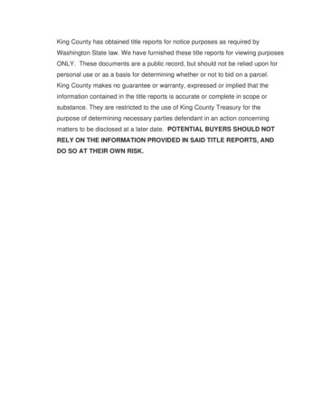
On indoor cabinet models, the consumer needs to installthe condensate evaporator heater assembly (described inthe Installation section of this manual) onto the exteriorback wall of the cabinet. The melt water from thedefrost cycle will drain into a catch pan where it willthen be heated to the point of evaporation. The functionof the condensate evaporator’s heat element should bechecked routinely. Failure of the element could result inan over-flow condition for the assembly’s drain pan. Asimple check of the heater would be a touch test of thesurface temperature of the assembly’s housing. Thecondensate evaporator’s heat element is energizedcontinuously so the surface of the housing should alwaysbe hot to the touch. If testing the heat element with ameter, the element can be unplugged from its’ powersource and a resistance reading can be taken through theplug’s bladed terminals. The condensate heater is ratedto generate 125 watts of power, which translates toapproximately 106 ohms of resistance.It is recommended to check the operation and conditionof the evaporator coil and for signs of excessive icebuildup every 3 monthsAuto-Defrost Electronic Control: The ADfreezer comes equipped with an electronic control (asdescribed in the OPERATION section of this manual).The timer is factory set for a 24 minute defrost cycle tooccur at 4-hour intervals. Like a mechanical timer, theelectronic control will switch power from run mode(condensing unit and evaporator fans) to defrost mode(defrost heat element). Whereas the mechanical timeroperates strictly on a timed cycle, the duration of theelectronic control’s defrost cycle is controlled by thetemperature at the sensor probe “P2.” If the temperatureat this probe reaches 60 prior to the 24-minute timedcycle ending, the control will override the timed cycleand immediately switch power from the defrost mode tothe run mode. If temperature is not reached at probe“P2,” the defrost cycle will continue for the entire 24minute programmed cycle prior to returning to runmode. Energizing the defrost circuit in the electroniccontrol can be verified with the illumination of the“melting snowflake” and the letters “DE” appearing onthe control’s display screen.The electronic defrost circuit is equipped with a defrosttermination safety switch and is attached to one of theevaporator coil tubes (located inside the Unit CoolerAssembly). This switch senses temperature and will cutpower to the defrost heat element should the temperatureat the surface of the switch reach 100 F. This switchonly terminates power to the heat element and will notend the timed / temperature defrost cycle. Once themerchandiser has returned to run mode, the terminationsafety switch will re-set when the temperature at its’surface reaches 70 F.Warning! The defrost termination / safety switchfunctions as a possible fire protection device. Do notremove or by-pass the switch from the defrost circuit.Note: If an electronic control AD unit loses power andthe temperature at “P2” is less than 60 F, it willautomatically enter a defrost cycle after a two-minutedelay.Note: Certain models may contain a drain line heater toprevent ice from forming inside the drain tube.Solid Door Models and Maintenance:Cabinets designed for outdoor use will have a metal claddoor that has been insulated with the same urethanefoam insulation as the cabinet. For routine cleaning ofthe door’s exterior surface, a mild detergent diluted inwarm water should be adequate.Routine inspection of the door gasket seal isrecommended. If damage has occurred, replace thegasket.Hinge Spring Tension: A simple test of thespring-load tension is to open the door just enough toinsert two fingers between the surface of the cabinet andthe handle side of the door. When the fingers arewithdrawn, there should be enough tension set on thehinge spring-loads to slowly move the door to a closedposition. If the door does not move from this two-fingerlocation, it’s likely that either the spring-load requiresre-tensioning or lubrication. If the door moves part wayfrom the two-finger location but stops short of thecabinet, the compression of the gasket along the hingeside of the door should be checked. If there is too muchcompression, the door will bind when closed and shouldhave its hinge-mount location checked and possiblyadjusted. Removing the hinge covers will expose thespring-loads for tension adjustment or removal. Removalof the spring-load will expose the hinge-adjustment plateand mounting screws should hinge adjustment berequired. See Figure 2 for instruction regarding springload installation and adjustment.7
SPRING CARTRIDGE INSTALLATION INSTRUCTIONSFigure 1Figure 2Figure 31) Install No. 220 Hinge with Adjustment Plate.2) Assemble Spring Cartridge. Grease bushing end of pin prior to insertion into Stationary Bushing. Apply asmall amount of grease to the hinge-pin hole on the end of the Adjustment Collar Assembly. (Fig. 1).3) Place Thrust Washer and Stationary Bushing over square pin in the Hinge and insert the Adjustment Pin intothe Adjustment Collar. Using the Adjustment Pin, compress the Spring and place the Adjustment Collar overthe round pin (Fig. 2).4) Using the Adjustment Pin, turn the Adjustment Collar until the Pin contacts the Hinge. Then insert the StopPin in hole of Adjustment Collar (Fig. 3). CAUTION: The Stop Pin must fully seat on Adjustment Collar.Failure to do so may cause the Stop Pin to become dislodged. Inserting the Adjustment Pin more than halfwaythru the Adjustment Collar can cause partial push out of the Stop Pin. Repeat adjustment until desired tension isreached. The maximum tension is 6 holes or approximately 1-1/4 turns.5) Install Cover on Hinge.WARNING: Use safety glasses when installing and adjusting spring tension.Figure 2: Spring Install Instructions8
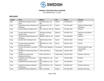
Solid Door Magnetic Gasket Replacement Instructions:1. Position solid door on a flat non-abrasive surface, exterior side down.2. Remove old gasket by grasping firmly at the corner and pulling away from the door frame extrusion.3. Inspect the extruded slot to insure there are no particles to interfere with the new gasket installation.4. Align new gasket with door corners and use thumb to press into frame.5. Start at one corner of the frame and begin pressing the new gasket into the slot. Using a non abrasivetool such as a hammer head works well for this application. Apply downward pressure while movingalong the permeter of the frame. Excessive pressure may strech the gasket and cause bulging at thecorners.Gasket Detail ViewStep 4Step 5Figure 3: Door Gasket Install9
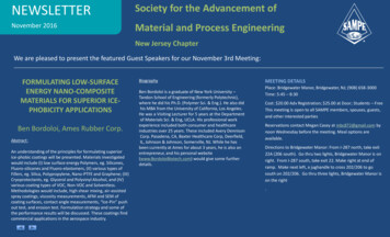
Electronic Control- AD Wiring Diagram W/Relay:10
Notes:11
Warranty:REFRIGERATED REACH-IN STORAGE FREEZERS: Seller warrants the freezer under normal use andservice, for one (1) year for the component parts (to be shipped by seller), and ninety (90) days for repair laborfrom the date of original shipment. The freezer compressor motor is warranted for five (5) years from the dateof original shipment. SELLER MUST BE CONTACTED AND PROVIDED A FREEZER SERIAL NUMBERFOR WARRANTY CLAIM. This applies only to goods installed in the United States, Canada or Mexico.Seller’s obligation under this warranty shall be limited to repair (subject to the limitations below) orreplacement of any part(s), F.O.B. Seller’s factory, which prove(s) defective within the applicable warrantyperiod. Seller reserves the right to inspect defective part(s) and may at Seller’s discretion require return ofpart(s) to Seller’s factory for inspection. The determination as to whether any defect exists shall be made inSeller’s sole judgement.GENERAL PROVISIONS APPLICABLE TO ALL WARRANTIES AND PRODUCTS: Seller shall notbe liable for any breach of any express warranty set forth above unless Seller is informed immediately upon thediscovery of defective part(s). The warranties described above are not assignable and shall operate only in favorof the original buyer/user. In event of any claim for breach of express warranty, Seller shall be responsible forlabor charges for repair or replacement of any defective part(s) or assembly only for defects reported to Sellerwithin ninety (90) days after the date of installation. ALL LABOR CHARGES SHALL BE AUTHORIZED ORAPPROVED BY SELLER PRIOR TO THE REPAIR OR REPLACEMENT OF PART(S). In all other events,Seller shall not be responsible for any labor charges. Labor charges shall only include standard straight timelabor hours at the site of product installation, and shall exclude charges for travel time, mileage, or otherpremium charges. These warranties shall not apply to any goods, or any part thereof, which may have beensubject to any damage in transit, accident, negligence, abuse or misuse, unauthorized alteration or repair, acts ofnature or failure to follow any of the Seller’s manuals or instructions, if in Seller’s sole judgement, such act,omission or event has detrimentally affected the physical condition, use or operating qualities of the product.SELLER MAKES NO WARRANTY, EXPRESS OR IMPLIED, BY REASON OF LAW, STATUE OROTHERWISE, INCLUDING ANY IMPLIED WARRANTY OF MERCHANTABILITY OR FITNESS FOR APARTICULAR USE OR PURPOSE, AND ALL IMPLIED WARRANTIES ARE HEREBY DISCLAIMED.SELLER SHALL NOT BE LIABLE FOR LOSS OF GOODS, MERCHANDISE OR OTHER PROPERTY,OR LOSS OF PROFITS, RESULTING FROM PRODUCT DEFECTS. IN NO EVENT SHALL SELLER’SLIABILITY UNDER ANY CIRCUMSTANCES FOR ANY BREACH OF CONTRACT OR FOR ANYOTHER CLAIM BY BUYER AGAINST SELLER EXCEED THE CONTRACT PRICE OF THE GOODSSOLD HEREUNDER WITH RESPECT TO WHICH SUCH CLAIM ARISES.MODEL NO.SERIAL NO.12
1070501 11/2020 Leer, Inc. 206 Leer Street, P.O. Box 206 New Lisbon, WI 53950 1-800-766-5337 www.leerinc.com STORAGE FREEZER INSTALLATION, OPERATION, AND SERVICE