Transcription
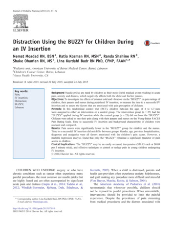
20-Mar-16Statics - CVLE 210 Dr Ayman TRADChapter 6 – Structural AnalysisChapter 6: Structural Analysis1
6.1 Simple TrussesStatics - CVLE 210 Dr Ayman TRADChapter 6 – Structural AnalysisA truss is a structure composed of slender membersjoined together at their end points. The memberscommonly used in construction consist of woodenstruts or metal bars.In particular, planar trusses lie in a single plane andare often used to support roofs and bridges.20-Mar-162
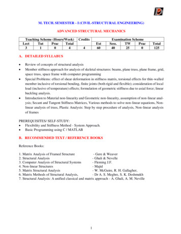
6.1 Simple Trusses20-Mar-16Statics - CVLE 210 Dr Ayman TRADChapter 6 – Structural AnalysisExample of a typical roof-supporting truss:In this figure, the roof load is transmitted to the truss at thejoints by means of a series of purlins . Since this loading acts inthe same plane as the truss, the analysis of the forcesdeveloped in the truss members will be two-dimensional.3
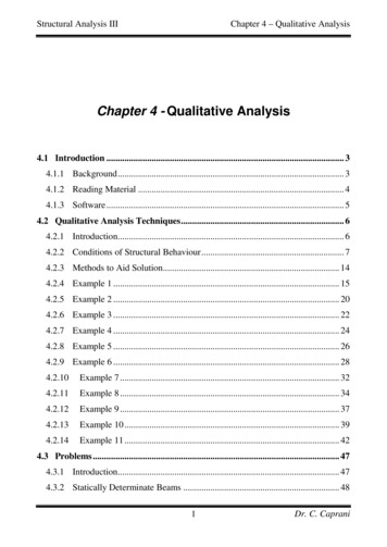
6.1 Simple Trusses20-Mar-16Statics - CVLE 210 Dr Ayman TRADChapter 6 – Structural AnalysisExample of a typical bridge truss:In the case of a bridge, the load on the deck is first transmittedto stringers, then to floor beams, and finally to the joints of thetwo supporting side trusses. Like the roof truss, the bridgetruss loading is also two-dimensional.4
6.1 Simple Trusses20-Mar-16Statics - CVLE 210 Dr Ayman TRADChapter 6 – Structural AnalysisWhen bridge or roof trusses extend over large distances, arocker or roller is commonly used for supporting one end. Thistype of support allows freedom for expansion or contraction ofthe members due to a change in temperature or application ofloads.5
6.1 Simple TrussesStatics - CVLE 210 Dr Ayman TRADChapter 6 – Structural AnalysisAssumptions for design: All loadings are applied at the joints. The members are joined together by smooth pins.20-Mar-166
6.1 Simple TrussesStatics - CVLE 210 Dr Ayman TRADChapter 6 – Structural AnalysisEach truss member act as a two-forcemember, and therefore the force acting ateach end of the member will be directedalong the axis of the member. If the force tends to elongate themember, it is a tensile force (T); if the force tends to shorten the member,it is a compressive force (C).In the actual design of a truss it is important to state whetherthe nature of the force is tensile or compressive. Often,compression members must be made thicker than tensionmembers because of the buckling or column effect that occurswhen a member is in compression.20-Mar-167
6.2 The Method of JointsStatics - CVLE 210 Dr Ayman TRADChapter 6 – Structural AnalysisIn order to analyze or design a truss, it is necessary todetermine the force in each of its members. One way to dothis is to use the method of joints.This method is based on the fact that if the entire truss is inequilibrium, then each of its joints is also in equilibrium.When using the method of joints, always start at a jointhaving at least one known force and at most two unknownforces. In this way, application of SFx 0 and SFy 0 yieldstwo algebraic equations which can be solved for the twounknowns.20-Mar-168
6.2 The Method of JointsThe correct sense of direction of an unknown member forcecan, in many cases, be determined “by inspection”.20-Mar-16Statics - CVLE 210 Dr Ayman TRADChapter 6 – Structural AnalysisIf not, always assume the unknown member forces acting onthe joint’s free-body diagram to be in tension; i.e., the forces“pull” on the pin.If this is done, then numerical solution of the equilibriumequations will yield positive scalars for members in tension (T)and negative scalars for members in compression (C).9
Example 1Statics - CVLE 210 Dr Ayman TRADChapter 6 – Structural AnalysisDetermine the force in each member of the truss shown below andindicate whether the members are in tension or compression.20-Mar-1610
Example 2Statics - CVLE 210 Dr Ayman TRADChapter 6 – Structural AnalysisDetermine the force in each member of the truss shown below andindicate whether the members are in tension or compression.20-Mar-1611
Example 3Statics - CVLE 210 Dr Ayman TRADChapter 6 – Structural AnalysisDetermine the force in each member of the truss shown below andindicate whether the members are in tension or compression.20-Mar-1612
6.3 Zero-Force MembersTruss analysis using the method of joints is greatly simplified ifwe can first identify those members which support no loading.Statics - CVLE 210 Dr Ayman TRADChapter 6 – Structural AnalysisThese zero-force members are used to increase the stability ofthe truss during construction and to provide added support ifthe loading is changed.The zero-force members of a truss can generally be found byinspection of each of the joints.20-Mar-1613
Statics - CVLE 210 Dr Ayman TRADChapter 6 – Structural Analysis6.3 Zero-Force MembersSo, AB and AF are “zero-force members”.20-Mar-1614
Statics - CVLE 210 Dr Ayman TRADChapter 6 – Structural Analysis6.3 Zero-Force MembersSo, DC and DE are “zero-force members”.20-Mar-1615
Statics - CVLE 210 Dr Ayman TRADChapter 6 – Structural Analysis6.3 Zero-Force MembersTruss analysis is greatly simplified when we firstidentify the “zero-force members”.20-Mar-1616
6.3 Zero-Force Members20-Mar-16Statics - CVLE 210 Dr Ayman TRADChapter 6 – Structural AnalysisFrom these observations, we can conclude that:“if only two non-collinear members form a trussjoint and no external load or support reaction isapplied to the joint, the two members must be zeroforce members.”17
Statics - CVLE 210 Dr Ayman TRADChapter 6 – Structural Analysis6.3 Zero-Force MembersSo, DA is “zero-force members”.20-Mar-1618
Statics - CVLE 210 Dr Ayman TRADChapter 6 – Structural Analysis6.3 Zero-Force MembersSo, CA is “zero-force members”.20-Mar-1619
Statics - CVLE 210 Dr Ayman TRADChapter 6 – Structural Analysis6.3 Zero-Force MembersTruss analysis is greatly simplified when we firstidentify the “zero-force members”.20-Mar-1620
6.3 Zero-Force Members20-Mar-16Statics - CVLE 210 Dr Ayman TRADChapter 6 – Structural AnalysisFrom these observations, we can conclude that:“if three members form a truss joint for which twoof the members are collinear, the third member is azero-force member provided no external force orsupport reaction is applied to the joint.”21
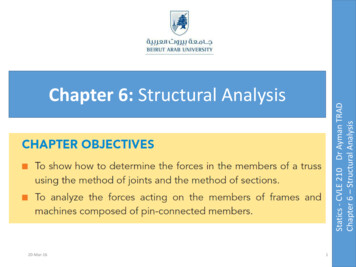
Example 6.4Statics - CVLE 210 Dr Ayman TRADChapter 6 – Structural AnalysisUsing the method of joints, determine all the zero-forcemembers of the Fink roof truss shown below. Assume alljoints are pin connected.20-Mar-1622
Example F6.4Statics - CVLE 210 Dr Ayman TRADChapter 6 – Structural AnalysisDetermine the greatest load P that can be applied to the trussso that none of the members are subjected to a forceexceeding either 2 kN in tension or 1.5 kN in compression.20-Mar-1623
6.4 The Method of SectionsWhen we need to find the force in only a few members of atruss, we can analyze the truss using the method of sections.Statics - CVLE 210 Dr Ayman TRADChapter 6 – Structural AnalysisIt is based on the principle that if the truss is in equilibriumthen any segment of the truss is also in equilibrium.Three equilibrium equations ( Fx 0, Fy 0, MO 0 ) canbe applied to the free-body diagram of any segment.20-Mar-1624
6.4 The Method of SectionsStatics - CVLE 210 Dr Ayman TRADChapter 6 – Structural AnalysisAs in the method of joints, there are two ways in which wecan determine the correct sense of an unknown memberforce:1. The correct sense of an unknown member force can inmany cases be determined “by inspection”.2. Always assume that the unknown member forces at thecut section are tensile forces, i.e., “pulling” on themember. By doing this, the numerical solution of theequilibrium equations will yield positive scalars formembers in tension and negative scalars for members incompression.20-Mar-1625
Example 6.5Statics - CVLE 210 Dr Ayman TRADChapter 6 – Structural AnalysisDetermine the force in members GE , GC , and BC of the trussshown below. Indicate whether the members are in tension orcompression.20-Mar-1626
Example 6.6Statics - CVLE 210 Dr Ayman TRADChapter 6 – Structural AnalysisDetermine the force in member CF of the truss shown below.Indicate whether the member is in tension or compression.Assume each member is pin connected.20-Mar-1627
Example 6.7Statics - CVLE 210 Dr Ayman TRADChapter 6 – Structural AnalysisDetermine the force in member EB of the roof truss shownbelow. Indicate whether the member is in tension orcompression.20-Mar-1628
6.6 Frames and MachinesFrames and machines are two types of structures which areoften composed of pin-connected members.Statics - CVLE 210 Dr Ayman TRADChapter 6 – Structural AnalysisFrames are used to support loads, whereas machines containmoving parts and are designed to transmit and alter the effectof forces.The forces acting at the joints and supports can bedetermined by applying the equations of equilibrium to eachof its members.Once these forces are obtained, it is then possible to designthe size of the members, connections, and supports using thetheory of mechanics of materials and an appropriateengineering design code.20-Mar-1629
Example 6.14Statics - CVLE 210 Dr Ayman TRADChapter 6 – Structural AnalysisDetermine the tension in the cables and also the force Prequired to support the 600-N force using the frictionlesspulley system shown below.20-Mar-1630
Example 6.16Statics - CVLE 210 Dr Ayman TRADChapter 6 – Structural AnalysisDetermine the horizontal and vertical components of forcewhich the pin at C exerts on member BC of the frame.20-Mar-1631
Example 6.17Statics - CVLE 210 Dr Ayman TRADChapter 6 – Structural AnalysisThe compound beam shown below is pin connected at B.Determine the components of reaction at its supports.Neglect its weight and thickness.20-Mar-1632
Example 6.20Statics - CVLE 210 Dr Ayman TRADChapter 6 – Structural AnalysisThe smooth disk shown below is pinned at D and has a weightof 20 lb. Neglecting the weights of the other members,determine the horizontal and vertical components of reactionat pins B and D .20-Mar-1633
20-Mar-1634Statics - CVLE 210 Dr Ayman TRADChapter 6 – Structural Analysis
Example 6.21Statics - CVLE 210 Dr Ayman TRADChapter 6 – Structural AnalysisThe frame shown below supports the 50-kg cylinder.Determine the horizontal and vertical components of reactionat A and the force at C .20-Mar-1635
20-Mar-1636Statics - CVLE 210 Dr Ayman TRADChapter 6 – Structural Analysis
20-Mar-16 9 The correct sense of direction of an unknown member force can, in many cases, be determined "by inspection". If not, always assume the unknown member forces acting on the joint's free-body diagram to be in tension; i.e., the forces